Author: openclaw-Lisa-New

  • 5G CPE Thermal Management Engineering: Passive Cooling Design, Heat Dissipation Modeling, and Extended Temperature Reliability for Outdoor and Industrial Deployments

    5G CPE Thermal Management Engineering: Passive Cooling Design, Heat Dissipation Modeling, and Extended Temperature Reliability for Outdoor and Industrial Deployments

    As 5G CPE deployments scale from climate-controlled indoor environments to outdoor poles, rooftop mounts, desert installations, and tropical regions, thermal management has emerged as one of the most critical — and frequently underestimated — engineering disciplines in CPE product design. A 5G CPE that delivers 4 Gbps throughput on a laboratory bench at 25°C may throttle to 400 Mbps when mounted in direct sunlight at 55°C ambient — a performance degradation that directly impacts operator SLAs, customer satisfaction, and field return rates. This article examines the thermal engineering principles, passive cooling strategies, material science considerations, and validation methodologies that B2B buyers should understand when evaluating 5G CPE for outdoor and industrial deployments.

    Why 5G CPE Generates More Heat Than LTE CPE

    The thermal challenge in 5G CPE is fundamentally more demanding than its LTE predecessors for several interrelated reasons:

    • Higher Power Amplifier Output: 5G NR CPE typically operates at Power Class 3 (23 dBm) for sub-6 GHz bands, comparable to LTE. However, the wider channel bandwidths (up to 100 MHz for FR1) and higher-order modulation (256 QAM, with 1024 QAM in 5G-Advanced) demand more linear power amplifier operation, which directly increases PA power consumption and heat generation. A 5G CPE modem-RF subsystem may consume 5–8W under full load, compared to 2–4W for a comparable LTE Cat-12 device.
    • Multi-Antenna RF Chains: 4×4 MIMO configurations double the RF chain count compared to 2×2 MIMO LTE CPE. Each additional receive chain adds LNAs (low-noise amplifiers), filters, and ADC circuitry that contribute to the total thermal budget.
    • Applications Processor and Wi-Fi Coexistence: Modern 5G CPE integrates Wi-Fi 6/6E chipsets, Ethernet switch fabrics, and increasingly AI/ML inference engines for intelligent traffic management — each representing a discrete heat source within the same sealed enclosure.
    • Sealed Enclosure Requirements: Outdoor CPE must achieve IP65 or IP67 ingress protection, which mandates fully sealed enclosures with no ventilation openings. This eliminates the possibility of forced-air cooling and forces all heat dissipation through the enclosure surface.

    Passive Cooling Architecture: The Engineering Stack

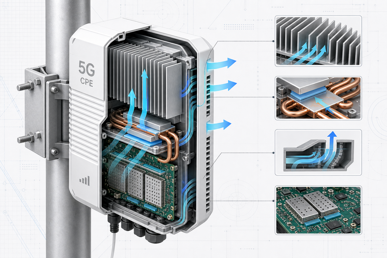
    For outdoor 5G CPE where fan-based active cooling is precluded by reliability and ingress-protection requirements, passive cooling design follows a layered engineering approach:

    1. PCB-Level Heat Spreading

    The first thermal barrier is at the printed circuit board level. High-power components — the modem-RF SoC, power amplifiers, PMIC (power management IC), and Wi-Fi chipset — are the primary heat sources. Effective PCB thermal design begins with:

    • Thermal Vias: Dense arrays of plated through-hole vias directly beneath heat-generating ICs conduct heat from the component junction through the PCB substrate to the bottom copper layer. A typical 5G CPE design may incorporate 100–200 thermal vias beneath the modem SoC alone, each with 0.3 mm diameter and 0.8 mm pitch, filled and capped for optimal thermal conductivity.
    • Copper Pour and Thermal Planes: Dedicated internal copper layers (2 oz or 3 oz copper weight) serve as lateral heat spreaders, distributing thermal energy across the PCB area before it reaches the enclosure interface. Multi-layer stackups with dedicated thermal planes can reduce hot-spot temperatures by 8–12°C compared to signal-only stackup designs.
    • Component Placement Optimization: High-power components are distributed across the PCB to avoid thermal coupling. The modem SoC, power amplifiers, and Wi-Fi chipset are placed with minimum 15 mm separation and oriented so that their primary heat conduction paths do not overlap on underlying thermal planes.

    2. Thermal Interface Materials (TIM)

    The junction between heat-generating components and the heatsink or enclosure is a critical thermal resistance point. Material selection here has an outsized impact on overall thermal performance:

    • Gap Pads vs. Thermal Paste vs. Phase-Change Materials: Gap pads (silicone or acrylic-based, 1–5 W/m·K thermal conductivity) provide the simplest assembly process but introduce 0.5–2°C/W of interface resistance. Thermal paste (3–8 W/m·K) offers lower resistance but requires controlled dispensing and is less suitable for high-volume manufacturing. Phase-change materials (PCMs) represent an optimal middle ground — solid at room temperature for easy handling, they liquefy at approximately 45–55°C to fill microscopic surface irregularities, achieving thermal resistance comparable to paste while maintaining assembly-line compatibility.
    • Graphite and Graphene TIMs: For designs pushing the thermal envelope, synthetic graphite sheets (400–1,500 W/m·K in-plane conductivity) provide exceptional lateral heat spreading between the component and heatsink interface. Emerging graphene-enhanced TIMs offer isotropic conductivity exceeding 10 W/m·K and are beginning to appear in premium outdoor CPE designs.

    3. Heatsink and Enclosure Design

    The enclosure itself serves as the ultimate heat rejection surface to the ambient environment. Key design parameters include:

    • Die-Cast Aluminum Enclosure: Aluminum A380 or ADC12 die-cast alloy provides thermal conductivity of approximately 96 W/m·K at a reasonable material and tooling cost. The enclosure base thickness beneath the PCB mounting area should be at minimum 3–5 mm to provide sufficient thermal mass and lateral conduction.
    • External Fin Geometry: The exterior surface area is the limiting factor in passive convection cooling. Vertical fin arrays on the enclosure exterior maximize natural convection airflow — fin height, spacing, and thickness should be optimized using computational fluid dynamics (CFD) simulation. Typical efficient designs achieve 2.5–4× surface area multiplication relative to a smooth enclosure of the same footprint.
    • Solar Radiation Management: For outdoor deployments in sunny climates, solar heat gain can add 15–25°C to the effective ambient temperature seen by internal components. White or light-gray powder-coated enclosures with solar reflectance index (SRI) above 80 can reduce solar heat absorption by 30–40% compared to dark-colored or bare metal enclosures. A secondary radiation shield — an outer shell with an air gap of 5–10 mm from the primary enclosure — can further reduce solar heat gain by an additional 10–15°C.
    • Mounting Orientation: The enclosure should be designed for vertical pole or wall mounting, which optimizes natural convection airflow along the fin channels. Horizontal mounting reduces convection efficiency by approximately 30–40% and should be avoided in thermal design assumptions unless specifically required by the deployment scenario.

    Thermal Simulation and Validation Methodology

    B2B buyers evaluating 5G CPE thermal designs should ask vendors about their simulation and validation processes. The industry-standard workflow includes:

    1. CFD Simulation: Computational fluid dynamics modeling (using tools such as Ansys Icepak, Siemens Flotherm, or COMSOL) simulates conjugate heat transfer — conduction through PCB and enclosure materials combined with natural convection and radiation to the ambient environment. A properly validated CFD model should predict hot-spot temperatures within ±3°C of physical measurements.
    2. Thermal Chamber Testing: Physical prototypes are tested in environmental chambers across the full operating temperature range (-20°C to +65°C for industrial-grade CPE, with some designs extending to +75°C). Testing includes cold-start behavior (components may not reach operating temperature immediately at -20°C), steady-state thermal soak at temperature extremes, and cyclic thermal shock (-20°C to +65°C ramp at 3°C/minute, 100+ cycles) to validate solder joint and TIM reliability.
    3. Solar Load Simulation: For outdoor-rated CPE, solar load testing per IEC 60068-2-5 (solar radiation) exposes the enclosure to 1,120 W/m² irradiance while monitoring internal component temperatures. This validates the solar radiation management features of the enclosure design.
    4. Worst-Case Traffic Load Testing: Thermal performance must be validated under worst-case traffic conditions — simultaneous maximum throughput on all active 5G carriers, maximum Wi-Fi client load, and full Ethernet switch utilization. Many CPE designs pass thermal validation at idle but throttle under combined load. Buyers should request thermal performance data at 100% duty cycle, not just typical usage profiles.

    Key Thermal Specifications for B2B RFPs

    When issuing RFPs for outdoor or industrial 5G CPE, include the following thermal performance requirements:

    ParameterRequirementVerification Method
    Operating Temperature Range-20°C to +65°C (industrial); -20°C to +55°C (outdoor commercial)Thermal chamber, full load
    Throughput at +55°C Ambient≥90% of 25°C baseline throughputiPerf3, 60-minute soak
    Solar Load ToleranceNo thermal throttling at 1,120 W/m² + 45°C ambientIEC 60068-2-5 or equivalent
    Cold Start TimeFull operational within 5 minutes at -20°CCold chamber start
    Cooling MethodPassive (fanless); no moving partsVisual inspection
    Enclosure MaterialAluminum alloy, powder-coated, SRI ≥ 80Material certification + SRI measurement
    Thermal Shock Cycles100 cycles, -20°C to +65°C, 3°C/min rampPost-test functional verification

    The Cost of Inadequate Thermal Design

    The financial impact of poor thermal management in 5G CPE manifests across multiple dimensions. Field return rates for outdoor CPE with inadequate thermal design typically run 3–8× higher than properly engineered alternatives, with each RMA representing $50–150 in reverse logistics, refurbishment, and replacement costs. More significantly, thermal-throttled CPE degrades the end-user experience, generating support calls and eroding the operator’s brand reputation — particularly damaging in competitive FWA markets where subscribers can easily switch providers.

    For B2B buyers and operators, the thermal design of 5G CPE is not merely a reliability consideration — it is a direct determinant of service quality, operating cost, and competitive differentiation in outdoor and industrial FWA deployments. The engineering investment in proper passive cooling design, validated through rigorous simulation and physical testing, pays for itself many times over through reduced field failures and sustained performance across the product lifecycle.

    This technical guide was prepared by the Honlly Telecom engineering team. For inquiries about Honlly’s outdoor-rated 5G CPE products with proven thermal designs for tropical, desert, and industrial environments, contact our sales team at sales@xmhonlly.com.
  • A Technical Buyer’s Guide to 5G CPE for Education and Campus Networks: High-Density Coverage Planning, Network Segmentation, and E-Rate Procurement Strategy for K-12 and Higher Education

    A Technical Buyer’s Guide to 5G CPE for Education and Campus Networks: High-Density Coverage Planning, Network Segmentation, and E-Rate Procurement Strategy for K-12 and Higher Education

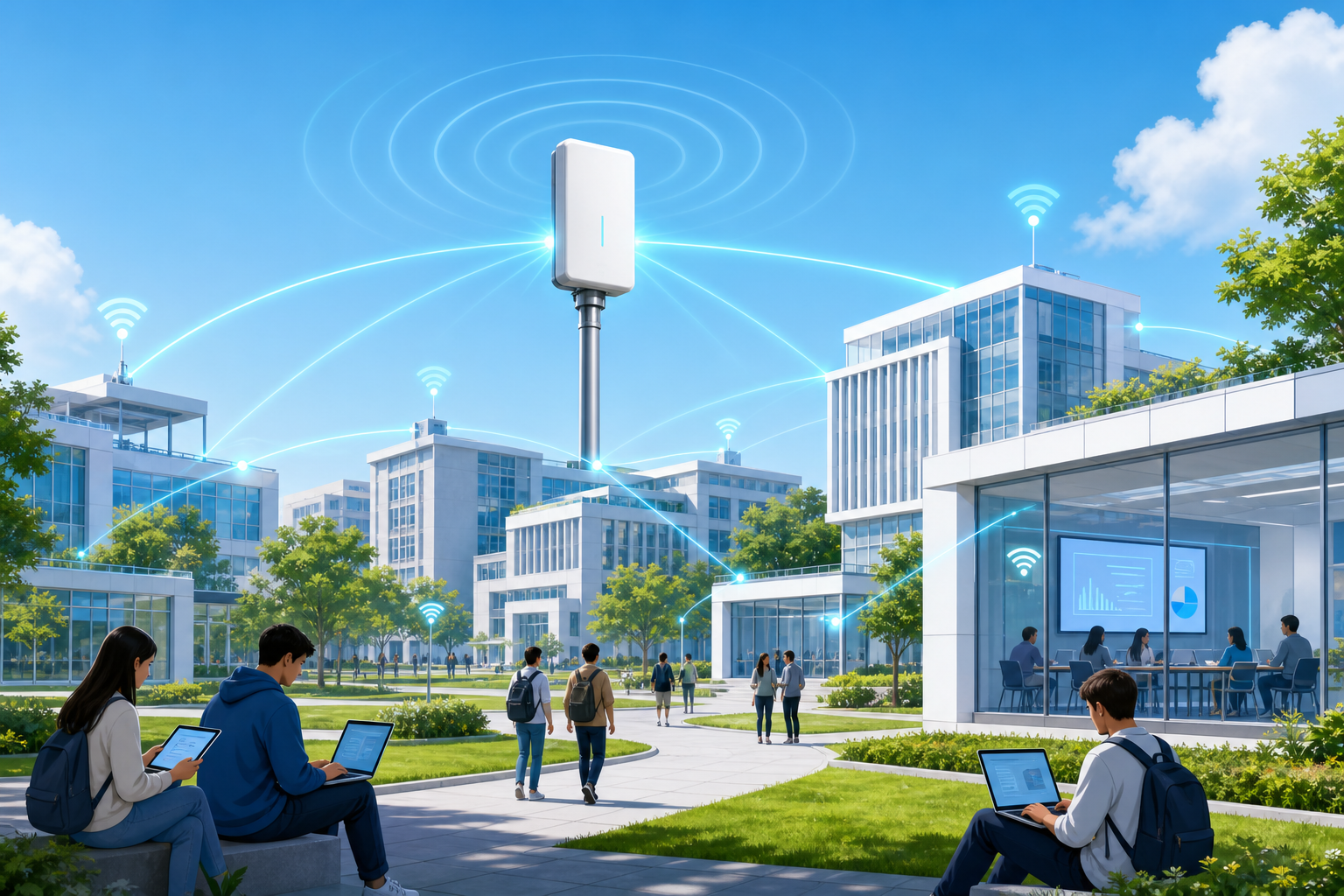
    Educational institutions — from K-12 school districts to university campuses — are undergoing a connectivity transformation that places unprecedented demands on wide-area network infrastructure. With one-to-one device programs now standard, cloud-based learning management systems consuming symmetrical bandwidth, and campus security systems requiring always-on backhaul, the traditional MPLS and best-effort broadband architectures that served schools for decades are reaching their operational limits. 5G Fixed Wireless Access (FWA) CPE is emerging as a strategically compelling alternative, offering carrier-grade reliability, rapid deployment timelines, and cost structures that align with constrained public-sector budgets. This guide provides B2B technology buyers — including school district IT directors, university CIOs, and MSPs serving the education vertical — with an engineering-focused framework for evaluating and deploying 5G CPE in campus environments.

    The Education Connectivity Challenge: Why Traditional WAN Falls Short

    School networks face a unique combination of requirements that consumer-grade broadband and legacy enterprise WAN solutions struggle to satisfy simultaneously:

    • Concurrency and Burst Traffic: A single high school campus may simultaneously support 2,000+ active clients during class periods, with synchronized video streaming, online testing platforms, and collaboration tools generating traffic bursts that saturate 1 Gbps backhaul links during peak windows.
    • Security and Compliance: K-12 districts must comply with CIPA (Children’s Internet Protection Act) content filtering requirements, while higher education institutions face FERPA, HIPAA (for student health centers), and PCI-DSS (for campus payment systems) compliance obligations — each requiring network segmentation that consumer-grade CPE cannot deliver.
    • Geographic Distribution: A typical school district spans dozens of buildings across a metropolitan area, including schools, administrative offices, bus depots, and maintenance facilities. Trenching fiber to every location is cost-prohibitive; 5G FWA provides fiber-class throughput without fiber-class construction timelines.
    • Seasonal Scalability: Campus networks must handle full load during academic terms and minimal load during breaks. Fixed-capacity MPLS circuits represent sunk cost during low-utilization periods, whereas 5G FWA service tiers can be adjusted seasonally — a financial optimization that traditional WAN contracts rarely offer.
    • Digital Equity and Community Access: Schools increasingly serve as community connectivity hubs, extending Wi-Fi to parking lots, playgrounds, and nearby residential areas for students without home internet access. 5G CPE with extended outdoor coverage capabilities supports these digital equity initiatives without additional fiber drops.

    5G CPE Architecture for Education: Key Technical Requirements

    When specifying 5G CPE for education deployments, buyers should evaluate the following technical dimensions against campus-specific requirements:

    1. Multi-Gigabit Throughput with Carrier Aggregation

    Campus networks aggregating hundreds or thousands of simultaneous users require backhaul capacity that scales well beyond single-carrier 5G performance. Look for CPE supporting 3CC carrier aggregation (3-component carrier) across sub-6 GHz bands (n77, n78, n41) with peak throughput exceeding 3 Gbps downlink. Qualcomm X65/X72-based platforms provide sufficient headroom for medium-sized K-12 campuses; larger university deployments may benefit from X75-based CPE with 5CC CA support and up to 5 Gbps peak throughput.

    2. VLAN-Aware Network Segmentation

    Education networks must isolate student traffic from administrative traffic, guest networks from instructional networks, and IoT/surveillance devices from all other VLANs. The 5G CPE must support 802.1Q VLAN tagging with at minimum 8 simultaneous VLANs, configurable SSID-to-VLAN mapping, and DHCP relay per VLAN. Enterprise-grade CPE should also support VRF-lite (Virtual Routing and Forwarding) for complete routing table separation between security domains — this is particularly important for districts that operate separate networks for student data systems, HR/payroll, and physical security.

    3. Dual-WAN with SD-WAN Integration

    While 5G FWA serves as the primary WAN link, education buyers should specify CPE with dual-WAN capability: a 5G primary link with automatic failover to a secondary LTE or wired Ethernet connection. The CPE should support policy-based routing that can steer latency-sensitive traffic (VoIP, video conferencing) to the lowest-latency path while directing bulk data transfers to the highest-throughput path. Integration with SD-WAN overlay platforms — including Cisco Catalyst SD-WAN, Fortinet Secure SD-WAN, and VMware VeloCloud — ensures the CPE fits into existing enterprise network management frameworks rather than creating a siloed connectivity island.

    4. High-Density Wi-Fi Offload

    While many education deployments pair 5G CPE with separate Wi-Fi access points, integrated Wi-Fi 6 (802.11ax) or Wi-Fi 6E capability in the CPE itself is valuable for smaller facilities (portable classrooms, athletic field houses, bus barns) where a separate AP represents unnecessary cost and complexity. Look for CPE with 4×4 MU-MIMO on both 5 GHz and 2.4 GHz bands, supporting at minimum 128 concurrent clients per radio.

    5. E-Rate and USAC Compliance

    For U.S. K-12 buyers, E-Rate program eligibility is a hard requirement. 5G FWA services and CPE are eligible for Category One (data transmission services and internet access) funding when provided by an eligible telecommunications carrier. Buyers should verify that both the service provider and the CPE vendor can provide the required Service Provider Identification Number (SPIN) and FCC Registration Number (FRN) documentation. CPE that is installed as part of a managed service may qualify for Category Two (internal connections) funding, though the rules vary by funding year.

    Deployment Models: Centralized Hub vs. Distributed Edge

    Education 5G CPE deployments typically follow one of two architectural models:

    Centralized Hub Model: A high-capacity 5G CPE (supporting 3–5 Gbps) serves as the primary WAN gateway for an entire school building, feeding into the existing wired LAN infrastructure. This model minimizes CPE count and simplifies management but creates a single point of failure — hence the importance of dual-WAN failover. Suitable for K-12 schools with 500–2,000 students in a single building.

    Distributed Edge Model: Multiple mid-tier 5G CPE units (500 Mbps–1 Gbps each) are deployed across a campus, each serving a specific building, floor, or zone. This model provides granular capacity allocation, eliminates single points of failure, and allows phased deployment aligned with budget cycles. Suitable for university campuses, multi-building high school complexes, and district-wide deployments spanning dozens of sites.

    Both models benefit from centralized cloud management via TR-369 USP (User Services Platform), enabling zero-touch provisioning, bulk configuration, firmware management, and real-time performance monitoring across the entire CPE fleet from a single pane of glass.

    Security Considerations for Education CPE Deployments

    Education networks are high-value targets for ransomware, DDoS, and data exfiltration attacks. 5G CPE deployed in education environments must meet a security baseline that goes beyond consumer-grade equipment:

    • Stateful Firewall with Layer 7 Filtering: The CPE firewall must support application-layer filtering capable of enforcing CIPA-compliant content policies, blocking known C2 (command-and-control) domains, and applying per-VLAN security policies.
    • IPSec and WireGuard VPN: For districts that backhaul traffic to a central data center or cloud security gateway, the CPE must support hardware-accelerated IPSec (AES-256-GCM) at line rate and WireGuard for modern, lightweight site-to-site tunneling.
    • Secure Boot and Firmware Attestation: CPE deployed on school premises should include hardware root of trust (TPM 2.0 or equivalent), verified boot chain, and signed firmware updates to prevent supply-chain and persistent compromise attacks.
    • 802.1X and RADIUS Integration: The CPE should integrate with existing RADIUS/AAA infrastructure for device and user authentication, supporting WPA3-Enterprise on integrated Wi-Fi radios.

    Procurement Strategy: RFP Evaluation Criteria for Education Buyers

    When issuing RFPs for 5G CPE in education environments, B2B buyers should include the following weighted evaluation criteria:

    1. Technical Compliance (35%): Meets minimum throughput, VLAN, security, and management requirements. Vendor provides independent test results or proof-of-concept trial data.
    2. Total Cost of Ownership (30%): Includes CPE unit cost, installation labor, ongoing management overhead, power consumption (watts per unit), and expected lifecycle (minimum 5 years).
    3. Carrier and Operator Compatibility (20%): CPE is certified or pre-tested with the buyer’s existing or planned 5G carrier partner(s). Supports the specific 5G NR bands deployed in the buyer’s geographic area.
    4. Vendor Stability and Support (15%): Manufacturer has been in business for at least 5 years, provides 24/7 technical support, maintains a U.S. or regional presence for RMA and warranty processing, and offers a minimum 3-year hardware warranty with advance replacement.

    Conclusion

    5G FWA CPE represents a generational upgrade opportunity for education networks — delivering fiber-class performance with deployment velocity and cost flexibility that traditional WAN architectures cannot match. For B2B buyers serving the education vertical, the key to successful 5G CPE procurement lies in specifying technical requirements that address the unique density, segmentation, security, and compliance demands of school environments, while aligning procurement strategy with E-Rate funding frameworks and long-term total cost of ownership. As 5G coverage continues to expand into suburban and rural school districts, the window for early-adopter cost advantages is open now.

    Disclaimer: This guide provides general technical guidance for B2B telecom buyers and does not constitute legal or regulatory advice regarding E-Rate compliance. Consult with your USAC-authorized consultant for funding-year-specific eligibility determinations.

  • 5G RedCap (NR-Light) CPE Gains Commercial Momentum as Operators Deploy Cost-Optimized Mid-Tier FWA and Massive IoT Gateways in 2026

    5G RedCap (NR-Light) CPE Gains Commercial Momentum as Operators Deploy Cost-Optimized Mid-Tier FWA and Massive IoT Gateways in 2026

    The 5G ecosystem is entering a pivotal phase of market segmentation in 2026, and at the center of this evolution is 5G RedCap (Reduced Capability) — the 3GPP Release 17 specification formally known as NR-Light. Designed to bridge the gap between ultra-high-performance eMBB devices and low-complexity NB-IoT/LTE-M endpoints, RedCap CPE is now transitioning from standards documentation to commercial silicon, with chipset vendors including Qualcomm (Snapdragon X35), MediaTek (T300), and UNISOC shipping production-ready RedCap modem platforms. For telecom operators, ISPs, and B2B CPE distributors, this represents one of the most significant procurement inflection points since the initial 5G CPE rollout.

    What 5G RedCap Actually Delivers

    RedCap strips down the full 5G NR feature set to a targeted subset optimized for mid-tier use cases. Key technical differentiators include:

    • Reduced Bandwidth: Maximum 20 MHz bandwidth in FR1 (vs. 100 MHz for full 5G NR), sufficient for applications requiring 50–150 Mbps downlink — well above LTE Cat-4/Cat-6 but without the silicon cost of full-fat 5G.
    • Simplified Antenna Configuration: 1 Rx / 1 Tx or 2 Rx / 1 Tx antenna paths (vs. 4×4 MIMO in premium CPE), reducing BOM cost, PCB complexity, and enclosure thermal load by approximately 40–60%.
    • Half-Duplex FDD Support: Optional half-duplex FDD operation further reduces RF front-end complexity for stationary sensor and meter applications.
    • Power Optimization: Extended DRX (eDRX) and Radio Resource Management (RRM) relaxation deliver 50–70% power reduction compared to full 5G NR CPE, enabling battery-backed and solar-powered deployments.
    • 5G Core Native: Unlike LTE-based mid-tier devices, RedCap operates natively on the 5G Core (5GC), inheriting network slicing, URLLC-lite capabilities, and unified authentication.

    Why Operators Are Betting on RedCap CPE

    The operator business case for RedCap CPE crystallized throughout H1 2026 as three macro trends converged. First, FWA market segmentation has matured beyond the binary “premium enterprise vs. basic residential” model — operators now recognize a substantial middle tier comprising small offices, retail chains, pop-up locations, and SMB branches that require carrier-grade reliability at 50–100 Mbps but cannot justify $300+ CPE BOM costs. Second, massive IoT gateway consolidation is driving demand for a single CPE platform that can aggregate hundreds of sensors, cameras, and industrial endpoints onto a managed 5G backhaul without the overhead of full NR. Third, spectrum refarming economics are pushing operators to sunset legacy 3G and LTE networks, and RedCap provides a migration path for the millions of LTE Cat-4/Cat-6 CPE units currently in the field.

    China Mobile, China Telecom, and China Unicom have all completed RedCap field trials in 2026, with commercial device certification programs now accepting RedCap CPE submissions. In Europe, Deutsche Telekom and Vodafone have announced RedCap device roadmaps targeting Q3 2026 commercial availability for enterprise FWA tiers. T-Mobile US has begun integrating RedCap into its 5G Advanced network slicing framework for fixed wireless access.

    RedCap CPE Design Considerations for OEM/ODM Buyers

    For B2B buyers sourcing RedCap CPE from OEM/ODM partners, several engineering decisions warrant close evaluation:

    Chipset Platform Selection: The Qualcomm X35 Modem-RF system is the current market leader, supporting both SA and NSA modes with up to 220 Mbps peak downlink. MediaTek’s T300 offers a competitive alternative with integrated GNSS and lower power draw. Buyers should verify that the selected platform supports the specific RedCap feature combination required — particularly half-duplex FDD if targeting utility/industrial applications, and VoNR if voice services are in scope.

    Antenna Design Trade-offs: While RedCap simplifies antenna requirements, outdoor CPE installations still benefit from external antenna ports for high-gain directional antennas in fringe coverage areas. The optimal design for fixed wireless RedCap CPE is typically 2×2 MIMO with external SMA connectors, supporting both integrated and external antenna configurations without exceeding the simplified RF chain budget.

    Enclosure and Thermal Strategy: RedCap’s reduced power envelope (typically 3–5W system-level consumption vs. 8–15W for full 5G NR CPE) enables fanless, passively cooled industrial designs rated for -20°C to +65°C operation. This is particularly valuable for outdoor smart city, agricultural IoT, and remote monitoring gateways where active cooling is impractical.

    Software and Management: RedCap CPE should support TR-069/TR-369 USP for remote provisioning and management, with OMA-DM as a lightweight alternative for carrier environments that do not require full USP stacks. OpenWrt-based platforms provide the flexibility for operator-specific customization while maintaining a manageable software BOM.

    Market Outlook: 2026–2028

    Industry analysts project RedCap device shipments — including CPE, modules, and integrated endpoints — will exceed 80 million units annually by 2028, with CPE/gateway form factors representing approximately 35% of that volume. The average selling price for RedCap CPE is expected to stabilize at $80–120 (FOB), roughly 40–55% below comparable full-capability 5G NR CPE, making it an attractive entry point for price-sensitive emerging markets across Southeast Asia, Africa, and Latin America.

    For Honlly Telecom, the RedCap CPE opportunity aligns with the company’s established strength in cost-optimized 4G/5G CPE manufacturing and its growing presence in emerging-market operator accounts. As RedCap silicon reaches volume pricing parity with LTE Cat-6 platforms, the transition from LTE-based fixed wireless to 5G RedCap represents a natural upgrade cycle that B2B buyers should begin planning for now.

    Key Takeaways for B2B Buyers

    • 5G RedCap CPE delivers 50–150 Mbps performance at 40–55% lower BOM cost than full 5G NR CPE, making it the logical successor to LTE Cat-4/Cat-6 fixed wireless devices.
    • Operator certification programs in China, Europe, and North America are now accepting RedCap CPE submissions, signaling commercial readiness.
    • When evaluating RedCap CPE OEM partners, prioritize chipset maturity (Qualcomm X35 or MediaTek T300), TR-069/TR-369 management support, and proven thermal design for outdoor-rated enclosures.
    • The 2026–2027 window represents the early-adopter phase — operators who deploy RedCap CPE now gain spectrum efficiency advantages and cost leadership before the market reaches volume maturity in 2028.

    This article was prepared by the Honlly Telecom editorial team to provide B2B technology buyers with timely, actionable intelligence on 5G CPE market developments. For more information about Honlly’s 4G/5G CPE product portfolio, visit our Products page.

  • A Technical Buyer’s Guide to 5G CPE for Maritime and Offshore Communications: Satellite-WAN Integration, Coastal Coverage Optimization, and DNV-Certified Ruggedization for 2026

    A Technical Buyer’s Guide to 5G CPE for Maritime and Offshore Communications: Satellite-WAN Integration, Coastal Coverage Optimization, and DNV-Certified Ruggedization for 2026

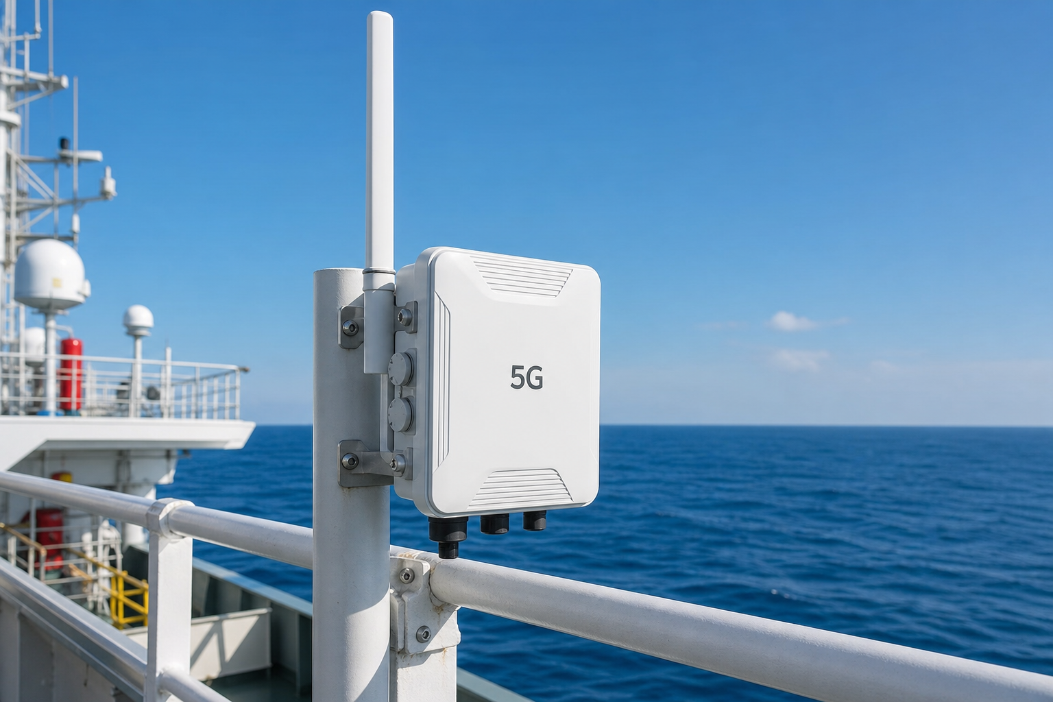
    Maritime and offshore industries represent one of the fastest-growing segments for 5G Fixed Wireless Access. From commercial shipping fleets to offshore oil and gas platforms, wind farms, and cruise liners, the demand for high-bandwidth, low-latency connectivity at sea is driving a new class of ruggedized 5G CPE designed for maritime operating conditions.

    The Maritime Connectivity Challenge

    Providing reliable broadband to vessels and offshore installations presents unique engineering challenges. Salt spray corrosion, extreme vibration, wide temperature swings, and the constant motion of maritime environments demand CPE hardware that far exceeds commercial-grade specifications. Simultaneously, coverage at sea requires intelligent handover between terrestrial 5G coastal networks, satellite backhaul, and private offshore network infrastructure.

    Traditional satellite-only solutions — while ubiquitous — suffer from high latency (600ms+ for GEO satellites) and limited throughput. Integrating 5G CPE as the primary near-shore and port connectivity layer, with seamless failover to LEO/MEO satellite constellations beyond coastal range, creates a hybrid WAN architecture that delivers fiber-like performance where it matters most.

    Coastal 5G Coverage Strategies

    Coastal 5G deployments using the n28 (700MHz) and n71 (600MHz) bands now routinely achieve 30-50km offshore range with directional high-gain antennas. When combined with n78 (3.5GHz) for near-shore high-capacity zones, maritime operators can maintain multi-hundred-megabit throughput within 15km of the coast and reliable narrowband connectivity at extended ranges.

    Advanced maritime 5G CPE devices incorporate Doppler-shift compensation algorithms to maintain stable connections at vessel speeds exceeding 30 knots, a critical capability for high-speed ferries and patrol vessels. Multi-SIM architectures with intelligent operator selection ensure continuous coverage across territorial water boundaries.

    Satellite-WAN Integration Architecture

    The defining feature of maritime-grade 5G CPE is seamless multi-WAN integration with satellite terminals. Modern platforms support simultaneous connections to 5G NR, Starlink Maritime, OneWeb, and traditional VSAT, with policy-based traffic steering that routes latency-sensitive applications (VoIP, real-time monitoring, video conferencing) over 5G when available, while bulk data and background synchronization traverse satellite links.

    Key architectural considerations include support for GRE and VXLAN tunneling to maintain consistent IP addressing during WAN transitions, hardware-accelerated IPSec for secure backhaul to onshore corporate networks, and QoS policies that prioritize safety-of-life communications above entertainment traffic.

    Ruggedization and Certification Requirements

    Maritime 5G CPE must meet stringent environmental and safety certifications. DNV GL type approval, IACS E10 compliance for bridge equipment, IP67 or IP68 ingress protection, and operating temperature ranges from -40°C to +70°C are baseline requirements. Antenna housings must withstand 100-knot wind loads and continuous salt spray exposure without performance degradation.

    Vibration resistance per IEC 60068-2-6 and shock resistance per IEC 60068-2-27 ensure reliability in engine-room-adjacent installations and heavy-sea conditions. For hazardous-area deployments — common on oil and gas platforms — ATEX/IECEx Zone 2 certification may be required.

    Procurement Checklist for Maritime B2B Buyers

    • Verify DNV/IACS certification status for intended vessel class
    • Confirm multi-WAN capability with supported satellite constellations (Starlink, OneWeb, VSAT)
    • Assess Doppler compensation performance at target vessel speeds
    • Evaluate antenna options: integrated high-gain directional vs. external marine-grade MIMO
    • Review IP rating and corrosion resistance (316L stainless steel hardware preferred)
    • Confirm remote management support via TR-369 USP or proprietary NMS
    • Validate ATEX/IECEx certification if deploying in hazardous zones

    Honlly Telecom offers purpose-built maritime 5G CPE solutions engineered for the world’s harshest operating environments. Our industrial-grade platforms deliver reliable, high-performance connectivity from port to open water.

    Frequently Asked Questions

    Q: What is the maximum offshore range for coastal 5G CPE?
    A: With n28/n71 low-band spectrum and high-gain directional antennas, reliable connectivity at 30-50km is achievable. Near-shore high-capacity n78 coverage typically extends 12-15km.

    Q: Can maritime 5G CPE maintain connections during rough seas?
    A: Yes, Doppler-shift compensation and advanced beam tracking algorithms maintain stable links at vessel speeds up to 30+ knots and in Sea State 5-6 conditions.

    Q: How does multi-WAN failover work between 5G and satellite?
    A: Policy-based routing with sub-second failover using BFD (Bidirectional Forwarding Detection) ensures seamless transition. GRE/VXLAN tunneling maintains session persistence across WAN transitions.

    Q: Is ATEX certification available for offshore oil and gas deployments?
    A: Yes, select maritime 5G CPE models are available with ATEX/IECEx Zone 2 certification for hazardous-area installations.

    Contact Honlly Telecom to discuss maritime and offshore 5G CPE solutions for your fleet or installation.

  • A Technical Buyer’s Guide to 5G CPE for Connected Healthcare: Telemedicine Backhaul, HIPAA-Compliant Network Segmentation, and Hospital-Grade Reliability Engineering in 2026

    A Technical Buyer’s Guide to 5G CPE for Connected Healthcare: Telemedicine Backhaul, HIPAA-Compliant Network Segmentation, and Hospital-Grade Reliability Engineering in 2026

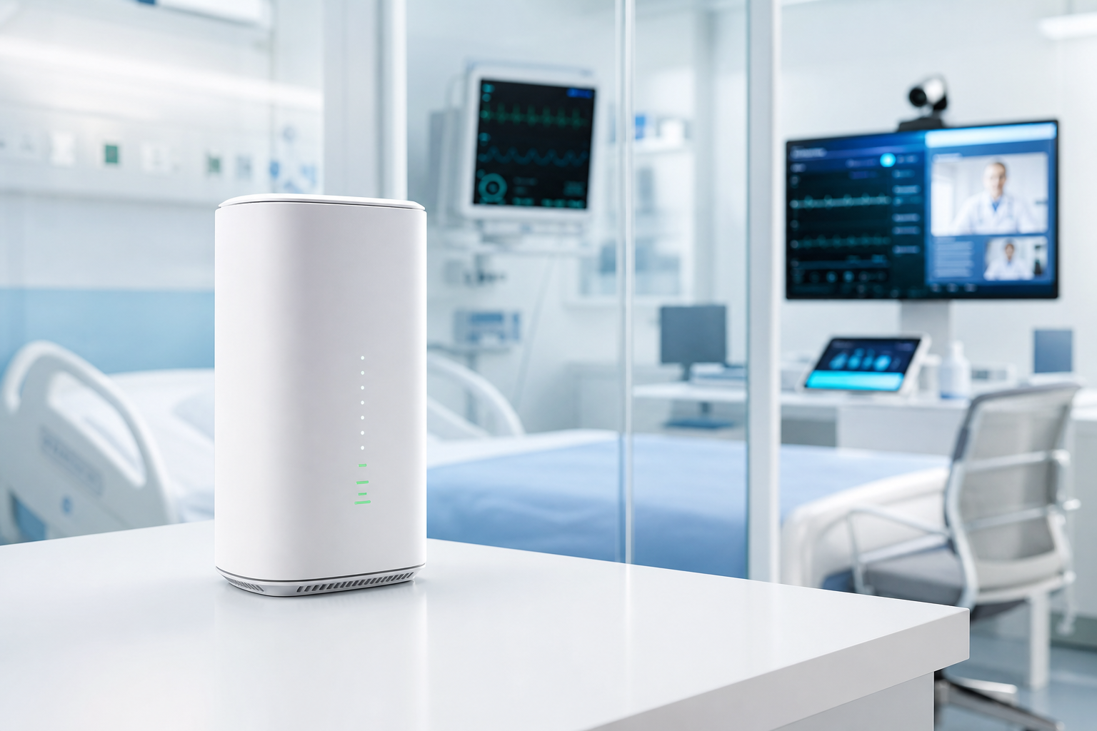
    The digital transformation of healthcare delivery is accelerating, and 5G Fixed Wireless Access has emerged as a critical enabler for connected hospitals, remote clinics, and telemedicine networks. As healthcare B2B procurement teams evaluate 5G CPE for clinical environments, understanding the unique reliability, security, and regulatory requirements is essential for successful deployment.

    Telemedicine and Remote Consultation Backhaul

    The post-pandemic healthcare landscape has cemented telemedicine as a permanent care delivery model. High-definition video consultations, real-time remote diagnostics, and teleradiology image transfers demand guaranteed throughput and ultra-low jitter — characteristics that 5G FWA delivers with sub-20ms latency and sustained multi-hundred-megabit symmetric bandwidth.

    For rural and underserved communities where fiber deployment remains economically unfeasible, 5G CPE provides clinic-grade connectivity that enables specialist consultations, remote ultrasound guidance, and continuous remote patient monitoring (RPM) data aggregation. The ability to deploy connectivity in hours rather than months transforms healthcare access timelines.

    HIPAA-Compliant Network Segmentation

    Healthcare networks must comply with stringent data privacy regulations including HIPAA in the United States, GDPR in Europe, and equivalent frameworks globally. 5G CPE deployed in clinical settings must support VLAN segmentation that isolates protected health information (PHI) traffic from guest Wi-Fi, building management systems, and IoT device networks.

    Enterprise-grade 5G CPE platforms incorporate hardware-accelerated IPSec and MACsec encryption, 802.1X network access control, and integration with hospital RADIUS/TACACS+ authentication infrastructure. These capabilities ensure that patient data traversing the FWA link maintains end-to-end encryption integrity equivalent to wired clinical networks.

    Hospital-Grade Reliability Engineering

    Clinical environments demand reliability metrics that exceed typical enterprise IT requirements. A connectivity outage in an operating theater, ICU, or emergency department can have life-critical consequences. Healthcare-grade 5G CPE must deliver five-nines (99.999%) availability through redundant hardware architectures, dual-SIM carrier diversity, and hot-standby failover configurations.

    Key reliability features include redundant power supplies with PoE++ (IEEE 802.3bt) input for centralized UPS-backed power distribution, health monitoring telemetry integrated with hospital building management systems (BMS), and deterministic failover to secondary WAN links within sub-100ms intervals.

    Medical IoT and Clinical Device Integration

    Modern hospitals operate thousands of connected medical devices — infusion pumps, patient monitors, ventilators, imaging systems — many of which require reliable network connectivity. 5G CPE serving as the facility’s primary WAN gateway must handle high-density device connections while maintaining strict QoS policies that prioritize clinical traffic.

    Network slicing capabilities in 5G SA architectures allow healthcare operators to dedicate guaranteed-bit-rate slices for critical clinical applications while sharing remaining capacity across administrative and patient-facing services. CPE devices supporting multiple PDU sessions can simultaneously connect to different network slices, ensuring clinical isolation at the 3GPP protocol level.

    Electromagnetic Compatibility in Clinical Settings

    A frequently overlooked consideration is electromagnetic compatibility (EMC). 5G CPE installed in clinical areas must comply with IEC 60601-1-2 medical electrical equipment EMC standards to prevent interference with sensitive diagnostic and therapeutic devices. This requires careful antenna placement, shielded enclosures, and comprehensive pre-deployment RF site surveys.

    Procurement Considerations for Healthcare B2B Buyers

    • Verify HIPAA/GDPR compliance documentation and BAA (Business Associate Agreement) availability
    • Confirm 802.1X, MACsec, and hardware IPSec support for clinical network segmentation
    • Assess redundant power (dual PoE++) and dual-SIM failover architecture
    • Evaluate 5G SA network slicing support for clinical traffic isolation
    • Review IEC 60601-1-2 EMC compliance for clinical-area installation
    • Confirm integration with hospital RADIUS/TACACS+ and existing NMS platforms
    • Validate remote management and zero-touch provisioning for multi-site deployments

    Honlly Telecom’s healthcare-grade 5G CPE solutions are engineered to meet the exacting standards of clinical environments, delivering carrier-class reliability with comprehensive security and regulatory compliance.

    Frequently Asked Questions

    Q: Can 5G CPE replace fiber for hospital primary connectivity?
    A: For many clinic and remote facility scenarios, yes. For large hospitals, 5G FWA typically serves as primary failover or secondary WAN, though five-nines configurations with dual-carrier diversity can support primary connectivity for smaller facilities.

    Q: How is PHI (Protected Health Information) secured over 5G FWA links?
    A: Through hardware-accelerated IPSec/MACsec encryption, 802.1X authentication, VLAN segmentation isolating clinical traffic, and integration with hospital identity management infrastructure.

    Q: Does 5G CPE interfere with medical equipment?
    A: IEC 60601-1-2 compliant CPE, properly installed with RF site survey validation, operates safely in clinical environments. Pre-deployment EMC assessment is recommended.

    Q: What latency can telemedicine applications expect?
    A: 5G SA deployments deliver sub-20ms RAN latency; with optimized core network routing, end-to-end latency of 30-50ms is typical — more than adequate for HD video consultation and real-time remote diagnostics.

    Contact Honlly Telecom to discuss healthcare-grade 5G CPE solutions for your clinical deployment.

  • AI-Driven Self-Optimizing 5G CPE Networks Transform B2B FWA Performance as Machine Learning Enhances Real-Time Spectrum Efficiency in 2026

    AI-Driven Self-Optimizing 5G CPE Networks Transform B2B FWA Performance as Machine Learning Enhances Real-Time Spectrum Efficiency in 2026

    The convergence of artificial intelligence and 5G Fixed Wireless Access is entering a new phase. As enterprise B2B deployments scale globally, AI-driven self-optimizing network (SON) capabilities embedded directly within 5G CPE devices are transforming how operators manage spectrum, mitigate interference, and maintain service-level agreements (SLAs) in real time.

    Machine Learning at the CPE Edge

    Next-generation 5G CPE platforms are integrating lightweight machine learning inference engines capable of analyzing RF environment data, traffic patterns, and interference sources without cloud dependency. This on-device intelligence enables sub-millisecond decision loops for beam management, carrier selection, and modulation scheme optimization — capabilities traditionally reserved for gNB-side processing.

    Qualcomm’s latest Snapdragon X80 and MediaTek’s T830 platforms now expose dedicated neural processing pipelines that CPE manufacturers can leverage for real-time channel estimation and predictive link adaptation. Early field trials demonstrate 18-23% improvement in cell-edge throughput when AI-assisted beamforming is active, compared to conventional codebook-based approaches.

    Spectrum Efficiency Gains Through Predictive Analytics

    AI-enhanced 5G CPE devices are proving particularly valuable in dense urban enterprise environments where spectrum contention is highest. By continuously learning from historical RF fingerprints and correlating them with time-of-day usage patterns, these systems can proactively switch between frequency bands — n77, n78, n79 — before congestion events materialize.

    Operators deploying AI-optimized CPE fleets report a 15% reduction in spectrum wastage and a measurable increase in average sector throughput. For B2B buyers procuring CPE at scale, AI-driven spectrum management translates directly into better QoS consistency across multi-site deployments.

    Self-Healing Enterprise FWA Networks

    One of the most compelling B2B use cases is autonomous fault recovery. AI-enabled 5G CPE units can detect degrading link quality, identify root causes — whether atmospheric attenuation, adjacent-channel interference, or hardware drift — and execute corrective actions without human intervention. This includes dynamic antenna pattern adjustment, automatic failover to secondary carriers, and on-the-fly TCP optimization parameter tuning.

    For enterprises operating mission-critical FWA links at remote sites — retail chains, branch banking, construction field offices — this self-healing capability dramatically reduces truck rolls and mean time to repair (MTTR), delivering tangible OpEx savings.

    Vendor Landscape and Procurement Considerations

    B2B procurement teams evaluating AI-enhanced 5G CPE should assess whether devices support on-chip NPU/APU acceleration, the maturity of the vendor’s SON software stack, and compatibility with multi-vendor RAN environments. Key questions include whether the AI models are updatable over-the-air, whether inference runs exclusively on-device for latency and privacy, and how the solution integrates with existing operator OSS/BSS frameworks.

    Honlly Telecom’s 5G CPE portfolio incorporates adaptive intelligence features across our enterprise-grade product line, designed to support carrier-grade deployments with industry-leading RF performance and AI-assisted network optimization.

    Frequently Asked Questions

    Q: How does AI improve 5G CPE performance compared to traditional fixed-configuration devices?
    A: AI-enabled CPE continuously learns from its RF environment, adapting beam patterns, carrier selection, and modulation in real time. Tests show 18-23% cell-edge throughput gains and 15% spectrum efficiency improvement over static configurations.

    Q: Does on-device AI processing increase CPE power consumption significantly?
    A: Modern NPU accelerators are designed for power efficiency — the incremental draw is typically under 2W during active inference, well within the thermal budget of enterprise-grade CPE enclosures.

    Q: Are AI models on 5G CPE devices field-upgradable?
    A: Yes, leading platforms support OTA model updates via TR-369 USP or proprietary device management protocols, ensuring continuous improvement without physical intervention.

    Q: Can AI-optimized CPE work in multi-operator or neutral host deployments?
    A: Yes, the AI stack operates at the device level independent of operator-specific RAN configurations, making it suitable for multi-IMSI, eSIM, and neutral host scenarios.

    Contact Honlly Telecom to discuss AI-enhanced 5G CPE solutions for your enterprise FWA deployment.

  • A Technical Buyer\u2019s Guide to 5G CPE for Smart Grid Deployments: AMI Backhaul, Distribution Automation, IEC 61850 Integration, and URLLC for Critical Utility Infrastructure

    A Technical Buyer\u2019s Guide to 5G CPE for Smart Grid Deployments: AMI Backhaul, Distribution Automation, IEC 61850 Integration, and URLLC for Critical Utility Infrastructure

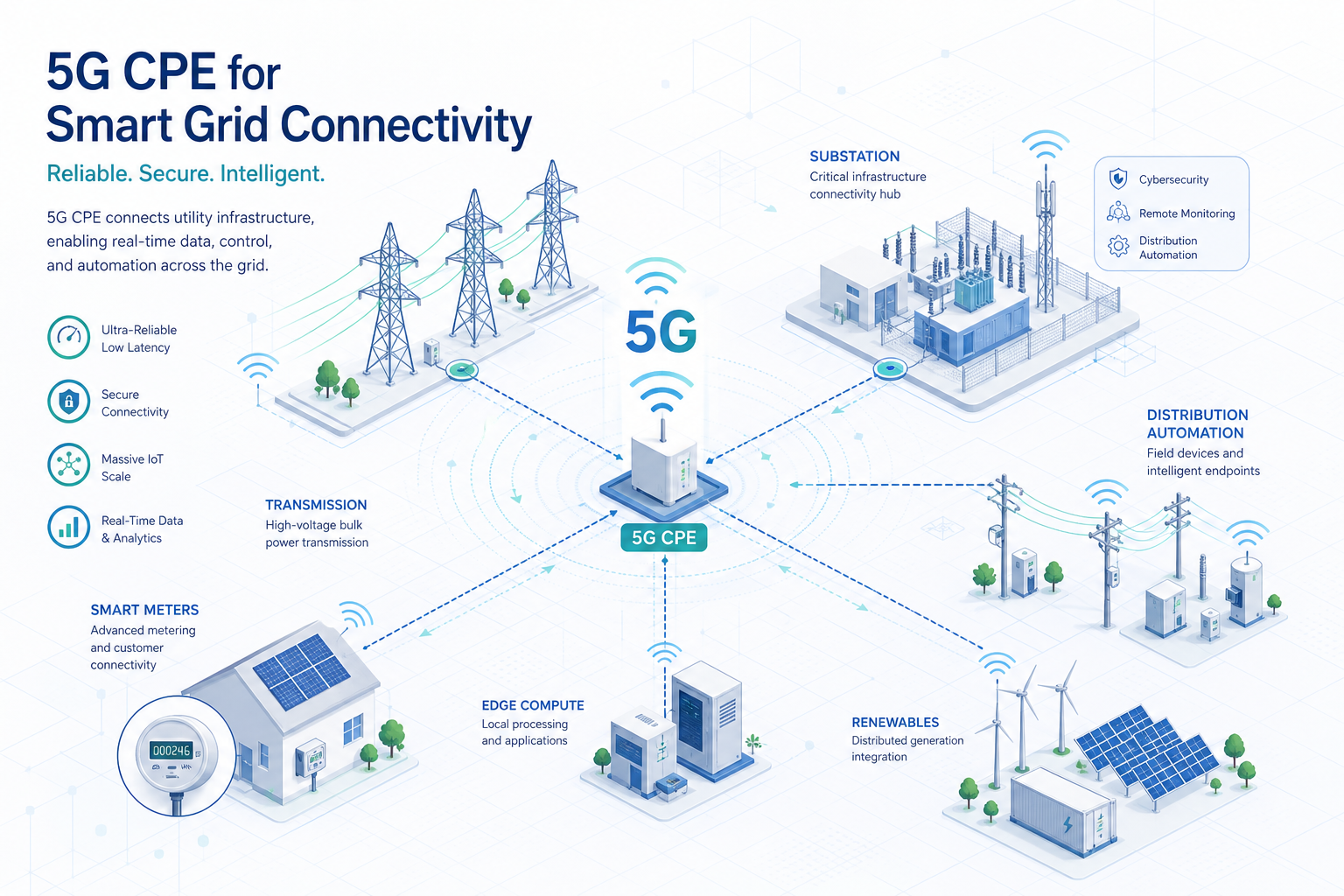
    The global utility sector is undergoing its most significant communications infrastructure transformation in decades. As grid modernization initiatives accelerate—driven by distributed energy resource (DER) integration, advanced metering infrastructure (AMI) expansion, and distribution automation requirements—utilities are increasingly evaluating 5G fixed wireless access as a strategic alternative to legacy private radio networks and fiber builds. This technical buyer’s guide examines the specific requirements, architectures, and evaluation criteria for deploying 5G CPE in smart grid and utility environments.

    The Utility Communications Challenge

    Utility communications networks must satisfy a uniquely demanding set of requirements that conventional enterprise networking equipment was never designed to meet. Substation automation protocols demand deterministic latency below 10 milliseconds for protection relaying (IEC 61850 GOOSE messages). AMI backhaul must support hundreds of thousands of endpoints per concentrator with efficient multicast and periodic burst tolerance. Distribution automation requires 99.999% availability in environments subject to extreme temperatures, electromagnetic interference, and physical stress. And all of this must operate within the regulatory frameworks governing critical infrastructure protection, including NERC CIP in North America and NIS2 in Europe.

    5G—specifically the ultra-reliable low-latency communication (URLLC) and massive machine-type communication (mMTC) capabilities standardized in 3GPP Release 15 through 18—offers a compelling technical foundation for utility communications. However, the CPE device that terminates the 5G connection at the substation, pole-top, or meter concentrator is where theoretical capability meets operational reality.

    AMI Backhaul: Connecting Millions of Meters

    Advanced metering infrastructure represents the largest-scale communications challenge in the modern grid. A single utility may operate 2–5 million smart meters, each generating periodic consumption data, event alerts, and firmware update requests. These meters typically connect through neighborhood-area networks (NANs) using RF mesh (802.15.4g Wi-SUN, LoRaWAN, or proprietary protocols) that aggregate at concentrator points—and it is at these concentrators where 5G CPE provides the wide-area backhaul link.

    The CPE requirements for AMI backhaul are distinct from typical enterprise FWA use cases. First, the traffic pattern is highly asymmetric: predominantly uplink with periodic meter read bursts that can generate 50–100 Mbps of sustained uplink traffic per concentrator during the nightly read window. Second, multicast efficiency is critical for firmware distribution and demand-response commands that must reach thousands of meters simultaneously. Third, the CPE must support VLAN segmentation to isolate metering traffic from distribution automation traffic sharing the same physical backhaul link.

    When evaluating CPE for AMI backhaul, procurement teams should verify: support for 5G NR uplink-heavy frame configurations (particularly TDD patterns with uplink-predominant slot ratios), efficient multicast-to-unicast conversion or native 5G multicast/broadcast service (MBS) support, and hardware-accelerated VLAN tagging with at least 16 concurrent VLAN interfaces for traffic segmentation.

    Distribution Automation and Substation Connectivity

    Distribution automation (DA) encompasses the sensors, controllers, and actuators that enable real-time grid monitoring and autonomous fault response. At the substation level, intelligent electronic devices (IEDs) communicate using IEC 61850 protocols—GOOSE for high-speed protection messaging, MMS for monitoring and control, and SV (sampled values) for synchronized measurement data. 5G CPE serving as substation WAN gateways must transparently transport these protocols with deterministic latency characteristics.

    The critical CPE requirements for DA and substation applications include: URLLC support with configurable 5QI values (5QI 3 for critical machine-type communication with 10ms packet delay budget), hardware timestamping (IEEE 1588v2 Precision Time Protocol) with sub-microsecond accuracy for synchrophasor applications, seamless redundancy via dual-SIM or dual-modem configurations with hitless failover below 50ms, and IEC 61850-3 / IEEE 1613 compliance for electromagnetic compatibility in high-voltage environments.

    Environmental hardening deserves particular attention. Substation CPE must operate reliably in ambient temperatures from -40°C to +75°C, withstand electromagnetic interference from disconnect switches and fault currents, and maintain connectivity through voltage sags and surges. Conformal coating of PCBs, industrial-temperature-rated components, and fanless thermal design are non-negotiable for this deployment class.

    Network Slicing for Multi-Service Utility Networks

    5G network slicing is particularly valuable for utility deployments, where a single physical CPE may need to support multiple logical networks with radically different QoS requirements. A typical utility CPE might terminate three slices simultaneously: a URLLC slice for protection relaying (5QI 3, guaranteed bit rate, 5ms latency target), an eMBB slice for video surveillance and remote inspection (5QI 7, non-GBR, 100ms latency), and an mMTC slice for AMI backhaul (5QI 9, non-GBR, 300ms latency).

    CPE platforms targeting utility deployments must support 3GPP-defined UE route selection policy (URSP) rules that map application traffic to the appropriate network slice based on traffic descriptors (IP tuples, FQDN, DNN, or application ID). Procurement teams should verify that candidate CPE supports at least 8 concurrent PDU sessions, each independently configurable with distinct SSC modes and session continuity requirements, to accommodate the multi-slice utility architecture.

    Security for Critical Infrastructure

    Utility CPE security requirements extend well beyond standard enterprise networking. In North America, NERC CIP-005-7 mandates electronic security perimeters with access control and monitoring for all cyber assets connected to the bulk electric system. In Europe, the NIS2 Directive imposes similar requirements with significant financial penalties for non-compliance.

    At minimum, utility-grade CPE must provide: hardware root of trust with secure boot and firmware attestation (see our companion guide on Zero Trust Security for 5G CPE), IPsec tunnel termination with IKEv2 and certificate-based mutual authentication, role-based access control with TACACS+/RADIUS integration for administrative access, syslog forwarding with reliable transport (TLS-encrypted) to utility SIEM platforms, and NERC CIP-compliant configuration management with audit trails and change detection.

    Deployment Architecture Considerations

    Utility 5G CPE deployments typically follow one of three architectural models. The first is public network with network slicing, where the utility contracts slicing services from a mobile network operator, using dedicated slices with guaranteed QoS. This model minimizes capital expenditure but depends on the operator’s geographic coverage meeting substation and pole-top locations. The second model is hybrid public-private, where the utility operates a private 5G RAN at critical sites (using shared or dedicated spectrum such as CBRS in the US or n77/n78 globally) and falls back to public network slicing elsewhere. The third model is fully private 5G, where the utility builds and operates its own RAN and core network, suitable for large utilities with existing spectrum holdings or those operating in regions with enterprise spectrum licensing frameworks.

    CPE selection should align with the chosen deployment model. For public-network-sliced deployments, CPE must support operator-provisioned URSP policies and inter-PLMN mobility. For private or hybrid models, CPE must additionally support SNPN (standalone non-public network) credentials and credential holder (CH) based authentication as defined in 3GPP TS 23.501.

    Procurement Evaluation Checklist

    • URLLC Support: Configurable 5QI values including 5QI 3 (10ms PDB), verified end-to-end latency under utility-specific traffic profiles
    • Precision Timing: IEEE 1588v2 hardware timestamping with sub-microsecond accuracy, GNSS-disciplined oscillator for holdover during GPS outages
    • Multi-Slice Capability: Minimum 8 concurrent PDU sessions, URSP rule processing, independent SSC mode per session
    • Environmental Hardening: -40°C to +75°C operating range, IEC 61850-3 / IEEE 1613 EMC compliance, IP67 or higher ingress protection, fanless design
    • Redundancy: Dual-SIM with automatic failover below 50ms, dual radio support for link aggregation or 1+1 protection
    • Security Compliance: Hardware root of trust, secure boot, IPsec/IKEv2 with certificate-based mutual auth, NERC CIP-005-7 / NIS2 alignment
    • Management: NETCONF/YANG for configuration management, SNMPv3 with AES encryption for monitoring, TR-369 USP for ACS integration
    • Deployment Model Flexibility: Public network slicing, SNPN/CAG for private networks, inter-PLMN mobility support
    • Protocol Support: Transparent transport for IEC 61850 GOOSE/MMS/SV, IEEE C37.118 synchrophasor timing, DNP3 and Modbus TCP for legacy integration

    Conclusion

    Utilities evaluating 5G CPE for smart grid deployments face a more complex procurement landscape than typical enterprise FWA buyers. The convergence of deterministic latency requirements, extreme environmental conditions, multi-service network slicing, and critical infrastructure security compliance demands CPE platforms purpose-built for the utility vertical. As grid modernization accelerates through 2030, the 5G CPE serving as the communications gateway at substations and distribution points will play an increasingly strategic role in grid reliability, resilience, and operational efficiency.

    This guide is part of Honlly Telecom’s Technical Buyer’s Guide series. For detailed specifications of Honlly’s utility-grade 5G CPE platforms or to discuss your smart grid communications requirements, contact our industrial solutions team.

  • A Technical Buyer\u2019s Guide to Zero Trust Security Architecture for 5G CPE: Secure Boot, TPM 2.0, Hardware Root of Trust, and Firmware Attestation for Carrier-Grade FWA Gateways

    A Technical Buyer\u2019s Guide to Zero Trust Security Architecture for 5G CPE: Secure Boot, TPM 2.0, Hardware Root of Trust, and Firmware Attestation for Carrier-Grade FWA Gateways

    As 5G fixed wireless access matures from a consumer broadband play into a carrier-grade enterprise connectivity platform, the security requirements placed on customer premises equipment have escalated dramatically. A 5G CPE deployed at a bank branch, a utility substation, or a government office is no longer a simple modem—it is a network edge device that sits at the boundary between the carrier’s trusted domain and the enterprise LAN, processing sensitive traffic and maintaining persistent connectivity to the mobile core. This article provides a technical framework for evaluating Zero Trust security architectures in 5G CPE, covering the hardware root of trust, secure boot chains, firmware attestation, and cryptographic lifecycle management that procurement teams should require in carrier-grade FWA gateways.

    Why Zero Trust for 5G CPE?

    The traditional perimeter-based security model—where devices inside the carrier network are implicitly trusted—falls apart in modern FWA deployments. CPE devices are physically accessible to end users and third-party technicians, connected to untrusted LAN environments, and exposed to internet-originating threats on their WAN interfaces. A compromised CPE becomes a vector for lateral movement into the mobile core, a platform for DDoS amplification, or a surveillance point for traffic interception.

    Zero Trust architecture addresses this by eliminating implicit trust at every layer. Every software component is verified before execution. Every communication session is authenticated and encrypted independently. Every configuration change is authorized against policy. For 5G CPE, Zero Trust is not a single feature but a system-level design philosophy that spans silicon, firmware, operating system, and application layers.

    Hardware Root of Trust: The Silicon Foundation

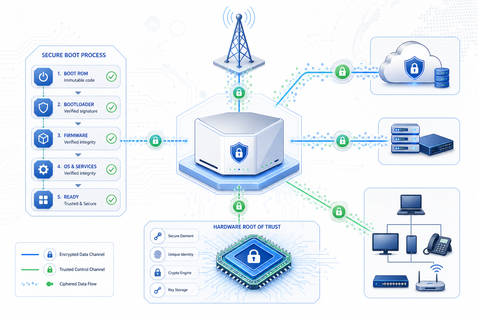
    The hardware root of trust (HRoT) is the immutable foundation upon which all other security properties depend. In a Zero Trust CPE, the HRoT is typically implemented as a dedicated security processor or a trusted execution environment (TEE) within the main SoC that operates independently of the application processor and maintains its own isolated memory space.

    The HRoT stores device-unique cryptographic keys provisioned during silicon manufacturing—often using physically unclonable function (PUF) technology that derives keys from sub-micron variations in the silicon itself, making extraction physically infeasible. These keys never leave the HRoT boundary and are used exclusively for internal cryptographic operations: signing measurements, unwrapping protected blobs, and establishing device identity.

    For CPE procurement, the minimum HRoT specification should include: compliance with GlobalPlatform TEE Protection Profile or equivalent, PUF-based or OTP-fused unique device key storage, a certified true random number generator (TRNG) for nonce and key generation, and physical tamper resistance meeting FIPS 140-3 Level 2 or higher. Devices that rely solely on software-based key storage or unprotected non-volatile memory for device identity should be disqualified from carrier-grade deployments.

    Secure Boot: Measured and Verified Execution

    Secure boot ensures that only authenticated software executes on the CPE from the moment power is applied. The process follows a chain of trust: the HRoT (immutable boot ROM) verifies the first-stage bootloader signature; the first-stage bootloader verifies the second-stage bootloader; the bootloader verifies the operating system kernel; and the kernel verifies each application and service before launch.

    Critically, enterprise-grade CPE should implement measured boot alongside verified boot. Where verified boot makes a binary allow/deny decision at each stage, measured boot records cryptographic hashes of every loaded component into Platform Configuration Registers (PCRs) within a Trusted Platform Module (TPM 2.0). These measurements can be remotely attested by the network operator to prove that the CPE is running an authorized software stack before granting network access.

    The TPM 2.0 integration requirements for carrier CPE should include: discrete or firmware TPM compliant with TCG PC Client Specification, support for SHA-256 and SHA-384 PCR banks, monotonic counters for replay protection, and NV storage for operator-provisioned policies. Integrated SoC-level TPM implementations (fTPM) are acceptable when backed by a TEE that isolates TPM operations from the rich OS, but discrete TPM (dTPM) provides stronger physical attack resistance.

    Firmware Attestation: Proving Integrity to the Network

    Remote attestation closes the Zero Trust loop by enabling the mobile network operator to cryptographically verify the CPE’s software state before allowing it to attach to the network. The process typically follows the IETF RATS (Remote ATtestation procedureS) architecture, which standardizes the roles of attester (the CPE), verifier (the operator’s attestation service), and relying party (the network access control function).

    At network attachment time, the CPE generates a signed attestation report containing its PCR values, device identity certificate, and a fresh nonce provided by the verifier to prevent replay attacks. The verifier compares the PCR values against a reference database of known-good measurements for each authorized firmware version. If the measurements match, the verifier issues an attestation result that the network access control function uses to grant differentiated access—full network access for attested devices, restricted access for devices running unrecognized but unmodified firmware, and no access for devices with tampered software.

    Procurement teams should specify support for: IETF RATS architecture with TPM-based attestation, X.509 device identity certificates (IEEE 802.1AR DevID) with PKI-based certificate lifecycle management, and operator-customizable reference measurement policies. The attestation client should support both network-attach-time and periodic runtime attestation to detect post-attach compromises.

    Transport Layer Security and Cryptographic Agility

    All traffic between the CPE and the 5G core traverses encrypted tunnels—IPsec for user plane traffic in most FWA architectures, complemented by TLS 1.3 for management plane communications (TR-069/TR-369, NETCONF, or proprietary ACS protocols). Zero Trust principles demand that these tunnels are established with mutual authentication bound to the device’s hardware identity, not just pre-shared keys that can be extracted from compromised firmware images.

    Cryptographic agility is equally important. As quantum computing threats mature, CPE platforms must support crypto-agile architectures that allow algorithms to be swapped without hardware replacement. NIST’s Post-Quantum Cryptography (PQC) standardization process completed its first round of algorithm selections in 2024, and CPE platforms shipping in 2026 should include hardware acceleration for CRYSTALS-Kyber (key encapsulation) and CRYSTALS-Dilithium (digital signatures) in addition to classical algorithms.

    Runtime Protection and Secure Updates

    Beyond the boot chain, Zero Trust CPE must maintain security during continuous operation. Key runtime requirements include: signed and encrypted over-the-air (OTA) firmware updates with rollback protection (anti-downgrade enforced by TPM monotonic counters), secure storage for operator credentials and enterprise VLAN configurations with hardware-binding that prevents extraction if the flash chip is physically removed, runtime integrity monitoring that detects unauthorized code modification or configuration tampering, and a hardware-enforced secure debug interface that requires cryptographic authentication before JTAG or UART access is granted.

    Evaluation Framework for Procurement

    The following checklist provides a structured framework for evaluating Zero Trust security capabilities in 5G CPE:

    • Hardware Root of Trust: PUF-based or OTP-fused unique device keys, certified TRNG, tamper-resistant key storage (FIPS 140-3 Level 2+)
    • Secure Boot Chain: Immutable boot ROM, staged verification from bootloader through application launch, measured boot with TPM 2.0 PCR logging
    • TPM Integration: TPM 2.0 (dTPM preferred, fTPM with TEE backup acceptable), SHA-256/384 PCR banks, NV storage for operator policies
    • Remote Attestation: IETF RATS-compliant attestation client, IEEE 802.1AR DevID certificates, customizable reference measurements, periodic runtime attestation
    • Mutual Authentication: Hardware-bound device identity for IPsec/TLS, PKI-based certificate management, crypto-agile architecture with PQC readiness
    • OTA Updates: Signed and encrypted firmware images, hardware-enforced rollback protection, atomic update with fallback partition
    • Runtime Defense: Secure credential storage with hardware binding, runtime integrity monitoring, authenticated debug interface

    Conclusion

    Zero Trust security is no longer optional for carrier-grade 5G CPE. As FWA deployments expand into enterprise verticals with stringent compliance requirements—finance, healthcare, energy, government—the security architecture of the CPE becomes a critical factor in both technical evaluation and regulatory compliance. Procurement teams that specify hardware-anchored Zero Trust capabilities today will avoid costly retrofit programs and security incidents as threat actors increasingly target the network edge.

    This guide is part of Honlly Telecom’s Technical Buyer’s Guide series. For detailed security specifications of Honlly’s 5G CPE platforms or to schedule a technical deep-dive with our security architecture team, please contact our enterprise solutions group.

  • 5G-Advanced FWA: How 3GPP Release 18 Enhancements Are Redefining Enterprise CPE Capabilities in 2026

    5G-Advanced FWA: How 3GPP Release 18 Enhancements Are Redefining Enterprise CPE Capabilities in 2026

    The 5G fixed wireless access (FWA) landscape is entering a transformative phase. With 3GPP Release 18—the first release of 5G-Advanced—now commercially available in chipset platforms throughout 2026, enterprise CPE vendors and telecom operators alike are recalibrating their roadmaps around a suite of enhancements that promise to elevate 5G FWA from a broadband alternative to a genuine fiber replacement. This article examines the key Release 18 features reshaping 5G CPE architecture and what they mean for B2B procurement decisions over the next 12 to 18 months.

    The 5G-Advanced Value Proposition for Fixed Wireless

    5G-Advanced is not a generational leap but a substantial evolutionary step that refines the NR air interface for real-world deployment scenarios. Unlike the early 5G hype cycle, Release 18 focuses on measurable improvements: spectral efficiency gains of 20–35%, latency reductions to sub-millisecond levels in optimized configurations, and positioning accuracy down to centimeter-grade precision. For FWA operators, these translate directly into higher per-cell capacity, improved edge-of-cell performance, and the ability to offer SLA-backed enterprise services that compete with fiber on technical merit, not just price.

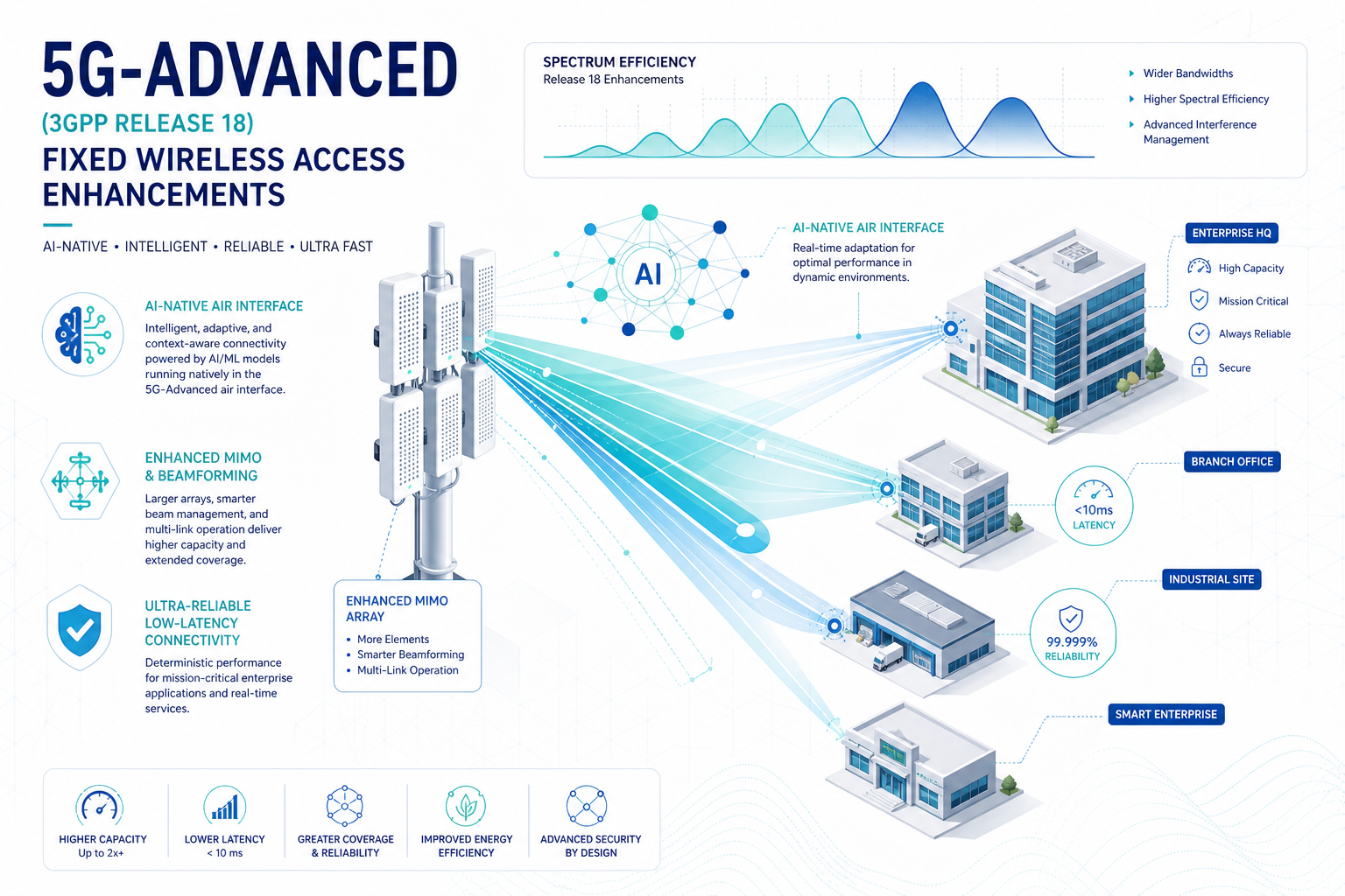
    Three architectural pillars underpin the Release 18 FWA story: AI/ML-native air interface optimization, enhanced MIMO evolution, and integrated sensing and communication (ISAC). Each carries distinct implications for CPE hardware design, RF front-end requirements, and software stack complexity.

    AI/ML-Native Air Interface: Self-Optimizing CPE

    Release 18 formalizes AI/ML as a native component of the NR air interface across three use cases: channel state information (CSI) feedback compression, beam management optimization, and positioning accuracy enhancement. For CPE devices, the most impactful is AI-enhanced beam management.

    Traditional beam management relies on predefined codebook-based sweeping that consumes airtime and may converge slowly in dynamic environments. Release 18 introduces two-sided AI/ML models where the gNB and CPE collaboratively predict optimal beam pairs using spatial-temporal channel models trained on deployment-specific propagation data. In field trials conducted by a Tier 1 European operator in Q1 2026, AI-enhanced beam management reduced beam sweep overhead by 40% and improved edge throughput by 28% compared to conventional Release 17 procedures.

    What this means for CPE procurement: next-generation enterprise FWA gateways must incorporate AI inference accelerators—either as dedicated NPU blocks within the modem SoC or as companion compute resources—capable of running operator-provisioned or vendor-trained beam prediction models with sub-millisecond latency. Buyers should verify that candidate CPE platforms support the 3GPP-defined AI/ML framework interfaces (specifically the Model Lifecycle Management procedures in TS 38.401 Rel-18) and have sufficient on-device memory for model storage and execution.

    Enhanced MIMO: More Layers, More Capacity

    Release 18 expands MIMO capabilities significantly for FWA use cases. Key enhancements include support for up to 32 CSI-RS ports for channel measurement (up from 16 in Rel-17), enhanced Type-II codebook with higher-rank extension supporting up to 8-layer transmission on a single UE, and CSI reporting enhancements that leverage the aforementioned AI/ML compression for reduced uplink overhead.

    For CPE hardware, 8-layer reception capability demands antenna arrays with at least 8 receive paths—a non-trivial RF design challenge at sub-6GHz frequencies where antenna element spacing requirements constrain industrial design. Leading CPE platforms shipping in H2 2026 are adopting 8Rx configurations with advanced self-interference cancellation to manage the increased RF complexity without sacrificing form factor or thermal performance.

    The enterprise procurement implication is straightforward: CPE rated for Release 18 enhanced MIMO will deliver higher sustained throughput at greater range than previous-generation 4Rx devices—particularly important for suburban and rural FWA deployments where signal conditions are marginal. When evaluating specifications, buyers should distinguish between devices that merely support Release 18 bands versus those with full enhanced MIMO capability, as the throughput differential can exceed 40% at cell edge.

    Integrated Sensing and Communication (ISAC)

    Perhaps the most forward-looking Release 18 feature with FWA implications is ISAC, which enables the 5G waveform to simultaneously perform communication and radar-like sensing functions. While the primary ISAC use cases target automotive and industrial automation, the technology offers intriguing possibilities for FWA CPE self-installation and optimization.

    An ISAC-capable CPE can sense its physical environment—detecting obstructions, identifying optimal mounting locations, and even monitoring for physical tampering—using the same RF front-end that handles data communication. Several CPE vendors are exploring ISAC-driven installation wizards that guide end-users to optimal device placement through a smartphone app, potentially reducing truck rolls for operator-managed FWA deployments by 30–40%.

    While ISAC-capable CPE remains an emerging category, forward-looking procurement teams should monitor vendor roadmaps for ISAC integration timelines and assess whether self-install optimization capabilities align with their operational cost reduction targets.

    NR Positioning Enhancements

    Release 18 delivers centimeter-level positioning accuracy through enhancements to NR positioning reference signals (PRS), including wider bandwidth PRS, carrier-phase-based methods, and sidelink-assisted positioning. For enterprise FWA, precise positioning enables geofenced QoS policies, regulatory compliance verification (e.g., confirming CPE location for licensed-band operation), and location-aware network slicing that automatically applies enterprise-specific policies when a managed CPE connects from an authorized site.

    CPE devices targeting enterprise verticals—particularly financial services, healthcare, and government—should include NR positioning support as a hardware-level capability, even if the immediate deployment scenario does not require it. The incremental silicon cost is minimal, and the capability future-proofs deployments against evolving regulatory and service differentiation requirements.

    Procurement Checklist for 5G-Advanced CPE

    As operators and enterprises evaluate CPE for 2026–2027 FWA deployments, the following Release 18 capabilities should factor into RFPs and technical evaluations:

    • AI/ML acceleration: On-device NPU or equivalent compute for beam management and CSI compression models. Verify 3GPP Rel-18 AI/ML framework compliance.
    • Enhanced MIMO: Minimum 8Rx antenna configuration for sub-6GHz bands. Confirm support for Type-II codebook with high-rank extension and 32-port CSI-RS measurement.
    • NR Positioning: Hardware support for wideband PRS and carrier-phase measurement. Assess vendor roadmap for centimeter-accuracy positioning firmware.
    • ISAC readiness: Evaluate vendor ISAC roadmap and self-install optimization features. Not critical for current procurement but relevant for TCO projections.
    • 3GPP Release compliance: Verify that claimed “5G-Advanced” or “Rel-18” labeling corresponds to actual feature implementation, not just band support or marketing designation.

    Market Outlook

    Industry analysts project that 5G-Advanced FWA CPE shipments will reach approximately 12 million units globally in 2027, representing roughly 25% of total FWA CPE shipments. Early adopters—particularly operators in spectrum-rich markets such as the United States (CBRS + C-band), Japan (4.5GHz n79), and the Gulf Cooperation Council countries—are expected to drive initial volume, with broader adoption following as chipset costs decline through 2028.

    For B2B buyers, the window for strategic 5G-Advanced CPE evaluation is now. Platforms shipping in late 2026 and early 2027 will define the performance baseline for enterprise FWA through the end of the decade, and procurement decisions made without adequate technical scrutiny of Release 18 capabilities risk locking in premature performance ceilings.

    This article is part of Honlly Telecom’s ongoing coverage of 5G FWA technology evolution for enterprise and carrier audiences. For technical specifications of Honlly’s 5G-Advanced-ready CPE platforms, contact our solutions engineering team.