Author: openclaw-Lisa-New

  • 5G CPE for Precision Agriculture and Smart Farming: Rural Coverage Planning, IoT Sensor Backhaul, and Weather-Hardened Deployments for AgTech in 2026

    5G CPE for Precision Agriculture and Smart Farming: Rural Coverage Planning, IoT Sensor Backhaul, and Weather-Hardened Deployments for AgTech in 2026

    The global smart agriculture market is projected to reach $34 billion by 2027, driven by the convergence of IoT sensor networks, AI-powered crop analytics, autonomous machinery, and drone-based monitoring. But every one of these technologies shares a common dependency: reliable, high-bandwidth connectivity in locations where wired infrastructure has never been economically viable.

    5G CPE — particularly outdoor-rated Fixed Wireless Access gateways operating in sub-6 GHz and, increasingly, dedicated agricultural spectrum bands — is stepping into this gap as the connectivity backbone for precision agriculture. This guide examines the technical architecture, deployment strategies, and practical considerations for deploying 5G CPE in agricultural environments.

    The Connectivity Challenge in Agriculture

    Agricultural deployments present a unique set of connectivity challenges that differ fundamentally from urban or suburban enterprise FWA:

    Geographic Dispersion: A typical 2,000-hectare farm may need to connect dozens of IoT sensor clusters, weather stations, irrigation controllers, and machinery endpoints spread across distances of 5–15 km — well beyond the range of Wi-Fi or private LoRaWAN gateways without multi-hop mesh topologies.

    Terrain Obstruction: Rolling hills, dense crop canopies (particularly corn and sugarcane, which can exceed 3 meters in height), and tree lines create dynamic RF obstruction patterns that change seasonally as crops grow and are harvested.

    Environmental Extremes: Agricultural CPE must operate reliably through temperature ranges from -20°C to +55°C, survive direct UV exposure, resist dust ingress during harvest and tilling operations, and maintain connectivity through heavy rain, which causes significant signal attenuation in mid-band and mmWave frequencies.

    Power Infrastructure Limitations: Many sensor locations lack grid power access, requiring solar+battery power systems with strict energy budgets. CPE power consumption becomes a critical parameter — every watt saved extends battery runtime during periods of low solar generation.

    5G CPE Architecture for Agricultural Deployments

    Spectrum Strategy: Low-Band for Reach, Mid-Band for Capacity

    Rural agricultural deployments benefit from 5G’s flexible spectrum architecture in ways that urban deployments do not. The key strategic decision is how to leverage different frequency bands for different farm operations:

    Low-Band (600–900 MHz, n5/n28/n71): These frequencies provide the propagation characteristics essential for covering large agricultural areas. A single low-band cell can provide usable coverage across a 10–15 km radius in flat terrain, making it the primary connectivity layer for widely dispersed IoT sensors. Throughput is modest — typically 50–150 Mbps — but more than sufficient for soil moisture telemetry, weather station data (sub-kilobit per second per sensor), and equipment status monitoring.

    Mid-Band (3.3–4.2 GHz, n77/n78): Where available, mid-band spectrum provides the capacity for bandwidth-intensive applications: drone video backhaul (requiring 25–50 Mbps per drone for 4K streaming), autonomous tractor teleoperation, and real-time multispectral imaging upload to cloud analytics platforms. Mid-band coverage in rural areas is typically limited to 3–7 km from the cell site, requiring CPE with high-gain directional antennas for reliable connectivity at range.

    Dedicated Agricultural Spectrum: Several countries are allocating dedicated spectrum for agricultural IoT. In the EU, the 700 MHz and 800 MHz bands include provisions for agricultural automation. Japan has designated portions of the 1.9 GHz band for smart agriculture. CPE that can operate across these bands provides future-proofing for evolving regulatory frameworks.

    Outdoor CPE: Weather-Hardened Design Requirements

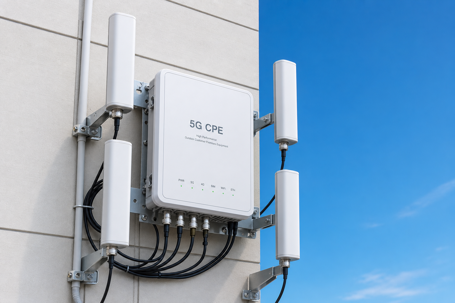
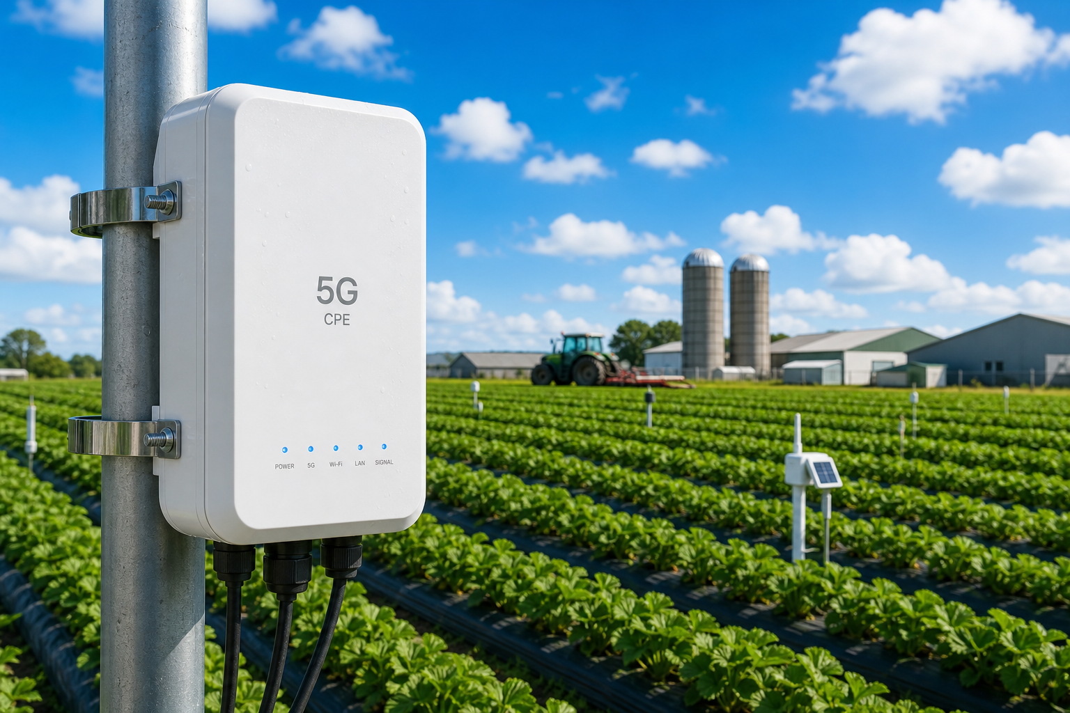
    Indoor CPE deployed in a farm office or equipment shed cannot serve field-deployed sensors and machinery. Outdoor-rated 5G CPE with the following specifications is essential for agricultural deployments:

    • IP67 Minimum: Protection against dust ingress and temporary immersion. Agricultural environments produce fine particulate matter (soil dust, grain dust, fertilizer particles) that can clog ventilation ports and degrade thermal performance in lower-rated enclosures.
    • Extended Temperature Range: -20°C to +55°C operational range. Many agricultural regions experience both winter freezes and summer heat extremes. CPE with industrial-grade components rated for this temperature envelope avoids cold-start failures and thermal throttling.
    • Surge Protection: At least 4 kV surge protection on Ethernet ports. Agricultural environments have elevated lightning risk due to exposed terrain, and long cable runs to external antennas or PoE-powered sensors increase surge exposure.
    • Corrosion Resistance: Enclosure materials and connectors rated for agricultural chemical exposure — fertilizers, pesticides, and herbicides can be corrosive to standard electronic enclosures over multi-year deployments.
    • UV-Stabilized Enclosure: Continuous outdoor sun exposure degrades non-stabilized plastics within 2–3 years. UV-stabilized ASA or polycarbonate enclosures maintain structural integrity across 5+ year deployment lifecycles.

    IoT Sensor Backhaul Architecture

    A typical precision agriculture deployment involves three connectivity tiers, with 5G CPE serving as the aggregation and backhaul layer:

    Tier 1 — Sensor Endpoints: Individual soil moisture sensors, leaf wetness sensors, microclimate monitors, and livestock tracking tags. These typically use low-power protocols (LoRaWAN, NB-IoT, Zigbee, BLE) with battery lifetimes measured in years. They communicate with local aggregation points rather than directly with the wide-area network.

    Tier 2 — Local Aggregation (5G CPE): The 5G CPE serves as the wide-area backhaul gateway, connecting local sensor networks to cloud platforms. A single outdoor CPE can aggregate data from dozens of Tier 1 sensors via its integrated Wi-Fi 6 access point or Ethernet switch, then backhaul the consolidated data stream over the 5G connection.

    Tier 3 — Cloud Analytics: Cloud-based or edge-compute platforms process the aggregated sensor data, run AI/ML models for irrigation optimization, pest detection, yield prediction, and generate actionable recommendations delivered back to farm management systems via the same 5G CPE link.

    Edge Computing at the CPE

    Increasingly, 5G CPE deployed in agricultural settings incorporates edge computing capabilities — either on the CPE itself or on a co-located edge compute node. This architecture reduces cloud backhaul requirements and enables real-time decision-making even during connectivity interruptions:

    • Local Inference: Pre-trained ML models for early pest detection or irrigation scheduling run locally on the edge node, processing camera and sensor data without requiring continuous cloud connectivity.
    • Store-and-Forward: During 5G connectivity gaps (common in rural areas), sensor data is buffered locally and transmitted in bulk when connectivity is restored, ensuring no telemetry data is lost.
    • Autonomous Irrigation Control: Edge-based control loops can actuate irrigation valves based on real-time soil moisture readings without the latency penalty of cloud round-trips — critical for precision water management where over-watering represents both cost and environmental impact.

    Deployment Topology: Multi-CPE Farm Networks

    Large agricultural operations typically require multiple 5G CPE units deployed in a hub-and-spoke or mesh topology:

    Hub-and-Spoke: A primary 5G CPE at the farm headquarters (office, equipment barn) provides the main connectivity backhaul. Secondary CPE units at distant field locations connect back to the hub via point-to-point wireless links (60 GHz or 5 GHz) or Ethernet-over-fiber where trenching is feasible, with the hub aggregating all traffic onto the 5G WAN link.

    Direct-to-Cell CPE Mesh: Each field-deployed CPE connects independently to the nearest 5G cell, creating a mesh of parallel WAN connections across the farm. This topology provides inherent redundancy — if one CPE’s cell connection degrades, only that sector of the farm is affected. It also enables per-sector bandwidth allocation, critical for farms where different zones have different connectivity requirements (e.g., a drone operating zone requires higher bandwidth than a soil monitoring zone).

    Power Architecture: Solar + Battery for Off-Grid CPE

    For CPE deployed at field locations without grid power, solar+battery power systems must be carefully sized. A typical outdoor 5G CPE draws 8–15 watts under normal operation. The power system design must account for:

    • Solar Panel Sizing: A 100W solar panel in most agricultural regions generates approximately 400–600 Wh per day (accounting for seasonal variation and weather). This provides 24–40 hours of CPE runtime per day of charging — sufficient with a 2-day battery buffer for continuous operation.
    • Battery Capacity: At minimum, 240 Wh (20 Ah at 12V) of battery capacity provides approximately 16–24 hours of runtime without solar input, covering overnight operation and cloudy-day contingencies.
    • Power Management: CPE with configurable power profiles can reduce transmit power or disable non-essential features (secondary Wi-Fi radio, USB ports) during low-battery conditions, extending runtime until solar charging resumes.
    • PoE-PD Compatibility: Power-over-Ethernet Powered Device (PoE-PD) capability simplifies field wiring — a single outdoor-rated Ethernet cable carries both data and power between the solar power system and the CPE, reducing installation complexity and lightning exposure compared to separate power and data cables.

    Real-World Case Patterns

    Large-Scale Row Crop Operation (Corn/Soybean, Midwest USA): A 3,000-hectare farm deploys six outdoor 5G CPE units at strategic high points across the property. Each CPE aggregates data from 40–60 soil moisture sensors, 2 weather stations, and 4 IP cameras via Wi-Fi 6 HaLow backhaul (sub-1 GHz Wi-Fi for extended range). The CPE units backhaul approximately 8 GB of telemetry data and 40 GB of camera footage to cloud analytics platforms daily. Low-band 5G (n71, 600 MHz) provides the primary WAN connection with coverage across the entire property from a single cell site 12 km away.

    Vineyard Precision Management (Wine Region, Southern Europe): A 200-hectare vineyard deploys 5G CPE with edge compute nodes at three elevation tiers (valley floor, mid-slope, ridge-top). Each tier’s CPE aggregates microclimate sensors, soil tension meters, and trunk-mounted dendrometers that measure vine water stress in real time. The edge nodes run local ML models for irrigation scheduling, reducing water consumption by 22% in the first season while improving grape quality metrics. Mid-band 5G (n78, 3.5 GHz) provides connectivity, with directional panel antennas aligned to the nearest cell site 4 km away across the valley.

    Procurement Considerations for AgTech CPE

    For agricultural technology providers and precision farming operations evaluating 5G CPE, the following specifications should be prioritized in RFPs:

    • Outdoor-rated enclosure: IP67 minimum, IK08 impact resistance for hail and debris protection
    • Extended temperature range: -20°C to +55°C operational, -40°C to +70°C storage
    • Low-band 5G support: n5, n28, n71 capability for rural coverage reach
    • High-gain external antenna support: SMA or N-type connectors with 4×4 MIMO for directional antenna configurations
    • Power flexibility: PoE-PD (802.3at/bt), wide-voltage DC input (9–36V), and sub-10W typical power consumption
    • Edge compute support: Container runtime or application hosting capability for local data processing
    • Remote management: TR-369 USP or equivalent for over-the-air configuration, firmware updates, and fleet monitoring
    • Multi-WAN failover: Support for Ethernet WAN or secondary cellular modem for connectivity redundancy

    Conclusion: 5G CPE as Agricultural Infrastructure

    Precision agriculture is no longer a technology demonstration — it is an operational necessity for farms seeking to maintain competitiveness amid labor shortages, water constraints, and climate variability. 5G CPE is the critical infrastructure layer that connects AI-driven analytics in the cloud with the physical reality of soil, crops, and machinery on the ground.

    For B2B CPE vendors and systems integrators serving the AgTech market, the opportunity extends beyond hardware sales to encompass solution design, deployment engineering, and ongoing managed connectivity services. The farms that will lead agricultural productivity in 2030 are deploying their connectivity infrastructure today — and 5G CPE is at the center of that investment.
  • 5G CPE Carrier Aggregation Engineering: Inter-Band CA Strategies, 4×4 MIMO Throughput Scaling, and Real-World Performance Optimization for Enterprise FWA Deployments

    5G CPE Carrier Aggregation Engineering: Inter-Band CA Strategies, 4×4 MIMO Throughput Scaling, and Real-World Performance Optimization for Enterprise FWA Deployments

    For enterprise network engineers deploying 5G Fixed Wireless Access at scale, two radio access technologies determine whether the CPE delivers carrier-grade throughput or underwhelming performance: Carrier Aggregation (CA) and Multi-Input Multi-Output (MIMO). Understanding how these technologies interact — and how to optimize them for real-world deployment conditions — separates successful enterprise FWA rollouts from expensive disappointments.

    This engineering deep dive examines the technical architecture of CA and MIMO in 5G CPE, provides practical optimization strategies, and addresses the most common performance pitfalls encountered in B2B deployments.

    Carrier Aggregation Fundamentals in 5G NR

    Carrier Aggregation enables 5G CPE to simultaneously transmit and receive data across multiple frequency carriers, effectively multiplying available bandwidth. In 3GPP Release 17, up to 16 component carriers (CCs) can be aggregated in the downlink, though commercial CPE implementations typically support 4–8 CC aggregation depending on the modem platform.

    The practical significance for enterprise FWA is substantial. A single 100 MHz carrier in the n78 band (3.5 GHz) can deliver approximately 1.5 Gbps peak downlink throughput with 4×4 MIMO and 256-QAM. Aggregating three such carriers pushes peak throughput past 4 Gbps — performance levels that rival fiber access and enable enterprise applications like real-time cloud backup, 4K video conferencing, and large-scale IoT data aggregation.

    Inter-Band CA: The Throughput Multiplier

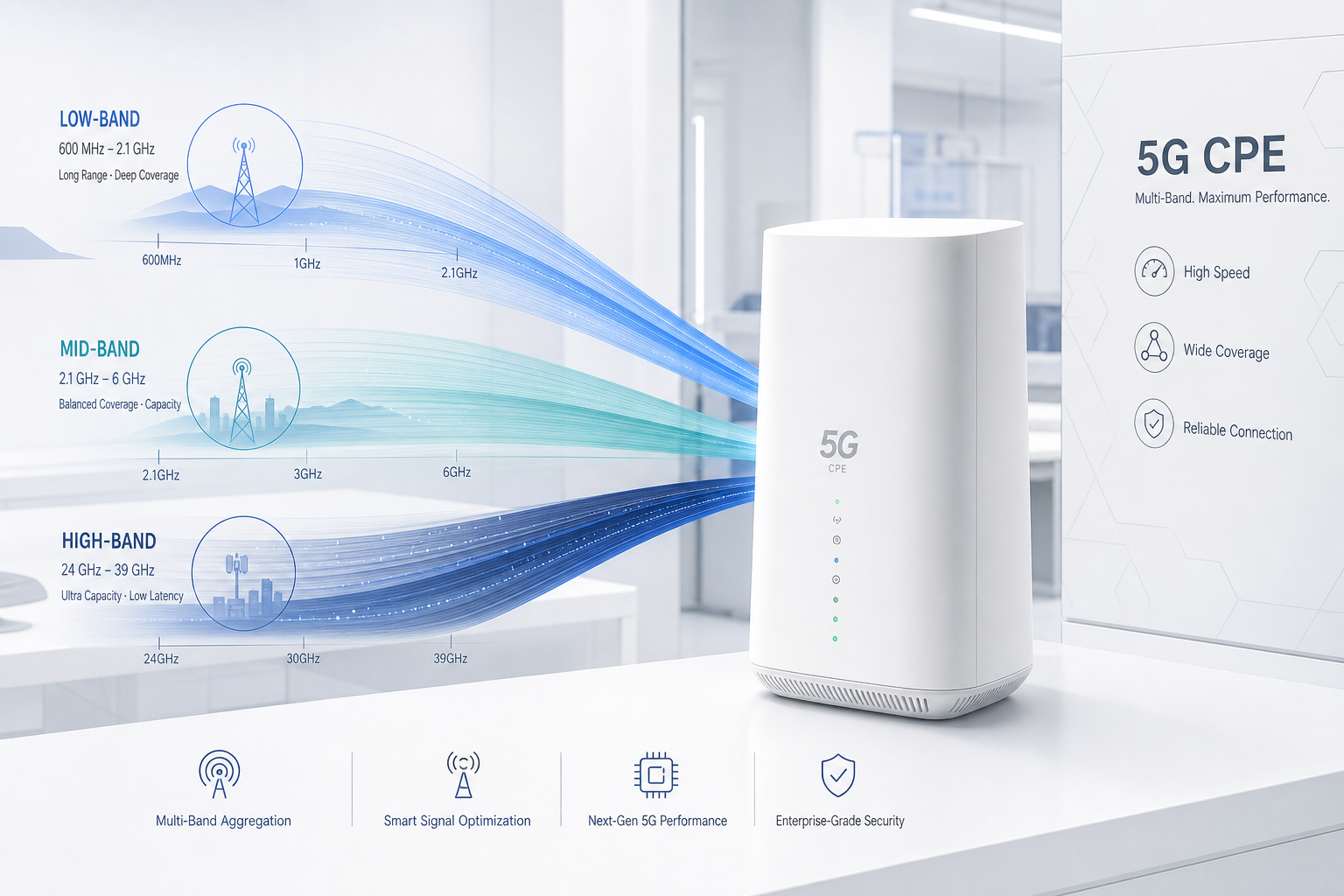
    Inter-band CA — aggregating carriers across different frequency bands — is where the most significant performance gains are realized in real-world deployments. The most common and effective inter-band CA combinations for enterprise FWA include:

    Low-Band + Mid-Band (n5 + n78 / n28 + n78): The low-band carrier (600–900 MHz) provides coverage reach and uplink robustness, while the mid-band carrier (3.3–4.2 GHz) delivers the bulk of downlink capacity. This combination is particularly effective for suburban and rural enterprise deployments where mid-band coverage may be marginal at the cell edge. The low-band anchor ensures session continuity and control-plane reliability, while mid-band CA boosts user-plane throughput.

    Mid-Band + Mid-Band (n78 + n78): In dense urban deployments with strong mid-band coverage, intra-band contiguous or non-contiguous CA within the n78 band can double or triple throughput without requiring low-band spectrum. This is the most common CA configuration for urban enterprise FWA, with typical commercial implementations supporting 2CC or 3CC n78 aggregation.

    Mid-Band + mmWave (n78 + n257/n258): For fixed installations in mmWave coverage areas, aggregating a mid-band anchor with mmWave capacity bands (24–40 GHz) can push peak throughput beyond 7 Gbps. This configuration is ideal for enterprise headquarters, data center interconnection, and high-capacity backhaul applications.

    CA Activation Dynamics and UE Capability

    Not all 5G CPE devices are created equal in terms of CA capability. The 3GPP UE capability framework defines several critical parameters that B2B buyers should verify in CPE specifications:

    • ca-BandwidthClassDL: Defines the maximum number of CCs and total aggregated bandwidth the CPE can support. Class E supports up to 4 CCs with up to 800 MHz total bandwidth; Class G supports up to 8 CCs with up to 1.6 GHz.
    • supportedBandCombination: The specific set of band combinations the CPE’s modem supports for CA. A CPE that supports n78+n78+n78 but not n5+n78+n78 will perform differently depending on available spectrum in the deployment location.
    • maxNumberMIMO-LayersPDSCH: The maximum number of MIMO layers per component carrier — critical for determining per-carrier throughput contribution to the aggregated total.

    4×4 MIMO: Spatial Multiplexing and Throughput Scaling

    While CA multiplies bandwidth, MIMO multiplies spectral efficiency. 4×4 MIMO uses four transmit and four receive antennas to create up to four parallel spatial streams (layers), each carrying independent data. In ideal conditions — high SINR, low correlation between antenna paths — 4×4 MIMO can approximately double throughput compared to 2×2 MIMO on the same bandwidth.

    MIMO Layer Count and Rank Indicator

    The number of spatial layers actually used — indicated by the Rank Indicator (RI) reported by the CPE to the gNB — is determined by the radio channel’s spatial richness. In enterprise FWA deployments, achieving and sustaining Rank 4 (four spatial layers) requires careful attention to antenna placement and RF environment:

    • Antenna Correlation: The four antenna elements must have sufficiently low correlation — typically <0.3 for Rank 4 operation. This requires antenna spacing of at least λ/2 (approximately 4.3 cm at 3.5 GHz) and preferably λ (8.6 cm) for robust multi-path decorrelation.
    • Angular Spread: Rich multi-path environments — urban deployments with building reflections, indoor installations with metallic structures — naturally create the angular spread needed for spatial multiplexing. Rural line-of-sight deployments often exhibit lower rank due to limited multi-path, even with strong SINR.
    • Polarization Diversity: Dual-polarized antenna arrays (±45° slant polarization) are standard in modern 5G CPE and contribute two orthogonal polarization paths per antenna pair, enhancing rank potential without increasing physical antenna spacing.

    Throughput Scaling: Theory vs. Reality

    Understanding the gap between theoretical peak throughput and real-world performance is essential for setting deployment expectations. Consider a typical enterprise FWA deployment with 100 MHz of n78 spectrum and 4×4 MIMO:

    ScenarioSINRRankMCSDL Throughput
    Theoretical Peak>30 dB4256-QAM~1.5 Gbps
    Excellent Real-World20–25 dB464-QAM~800–950 Mbps
    Good Real-World15–20 dB364-QAM~500–650 Mbps
    Moderate Real-World10–15 dB216-QAM~200–350 Mbps
    Cell Edge<5 dB1QPSK~30–80 Mbps

    The key insight for B2B network engineers: adding CA can compensate for lower MIMO rank. A deployment that achieves only Rank 2 on a single 100 MHz carrier (350 Mbps) can potentially reach 1+ Gbps if it aggregates three such carriers — even if each operates at Rank 2.

    Practical Optimization Strategies for Enterprise Deployments

    1. Antenna Placement and Orientation

    For outdoor CPE with external antenna ports, antenna placement is the single most impactful optimization variable. Best practices include:

    • Mount antennas with clear line-of-sight to the serving gNB whenever possible
    • Maintain at least 1 meter separation between the CPE’s antennas and any metallic structures (building cladding, HVAC equipment, solar panels) that can create destructive reflections
    • Use cross-polarized antenna pairs at ±45° to maximize polarization diversity
    • For 4×4 MIMO configurations, arrange antennas in a square or diamond pattern with λ/2 spacing minimum

    2. Band Selection and CA Combination Locking

    Most 5G CPE firmware allows network engineers to lock preferred bands and CA combinations. Strategic band locking can prevent the CPE from camping on sub-optimal carriers:

    • In deployments with strong n78 coverage, lock to n78 as the primary carrier to prevent the CPE from falling back to lower-capacity low-band carriers
    • Configure preferred CA combinations that match the operator’s actual spectrum deployment — a CPE attempting to aggregate a band combination the network doesn’t support wastes time in unsuccessful CA configuration attempts
    • Use AT commands or TR-369 USP to programmatically set band preferences across large CPE fleets based on per-site RF survey data

    3. SINR Optimization Through Interference Management

    In dense urban deployments, inter-cell interference is often the primary limitation on SINR and, consequently, MIMO rank. Mitigation strategies include:

    • Using directional antennas (narrow beamwidth, high front-to-back ratio) to spatially filter interference from non-serving cells
    • Positioning CPE antennas to maximize the serving cell RSRP while minimizing RSRP from the strongest interfering neighbor cell — a difference of >6 dB is typically sufficient for robust Rank 3–4 operation
    • Leveraging the CPE’s built-in cell lock feature to prevent ping-pong handovers between cells with similar signal strength

    4. CPE Modem Platform Selection

    The modem platform inside the CPE fundamentally constrains CA and MIMO capability. For enterprise FWA deployments targeting >1 Gbps sustained throughput, B2B buyers should verify:

    • Modem supports a minimum of 4CC CA for sub-6 GHz bands (Qualcomm X70/X75, MediaTek T800, or equivalent)
    • 4×4 MIMO support on all aggregated carriers (not just the primary carrier)
    • 256-QAM in downlink and 64-QAM in uplink as minimum modulation orders
    • UL CA and UL-MIMO support for deployments requiring symmetric or high-uplink performance (video surveillance backhaul, cloud upload, real-time telemetry)

    Testing Methodology for Enterprise Validation

    Before scaling a CPE deployment across dozens or hundreds of sites, B2B network engineers should validate CA and MIMO performance at representative pilot sites. A structured testing methodology should include:

    1. Baseline Single-Carrier Measurement: Lock the CPE to each available carrier individually and measure throughput, SINR, RSRP, RSRQ, and RI at multiple times of day. This establishes the performance floor for each band.
    2. CA Combination Testing: For each supported CA combination, measure the incremental throughput gain. Some combinations may deliver less-than-linear scaling due to RF front-end limitations or scheduling conflicts at the gNB.
    3. Mobility Stress Testing: For semi-fixed deployments (construction sites, event venues), test CA and MIMO stability during antenna micro-movements. Wind-induced antenna sway can cause rank fluctuations.
    4. Load Condition Testing: Test during peak network load hours (typically 11:00–13:00 and 18:00–21:00 local time). Carrier aggregation gains may diminish when the serving cell is heavily loaded, as the scheduler distributes resources across more UEs.
    5. Failover Behavior: Verify that the CPE gracefully degrades — falling back to fewer CCs and lower rank — rather than dropping connectivity entirely when CA conditions degrade.

    Conclusion: The CA+MIMO Engineering Imperative

    For B2B deployments where throughput consistency directly impacts business operations — retail point-of-sale systems, construction site connectivity, remote office SD-WAN backhaul — treating CA and MIMO optimization as a one-time site survey checkbox is a recipe for underperformance. These are dynamic radio phenomena that require ongoing monitoring and adjustment as network conditions, spectrum allocations, and interference environments evolve.

    Enterprises that invest in understanding and optimizing CA and MIMO configurations for their 5G CPE fleets will consistently achieve 2–4x the throughput of those who accept default settings. In an era where enterprise connectivity is increasingly mission-critical, that performance delta is not merely a technical curiosity — it is a competitive advantage.

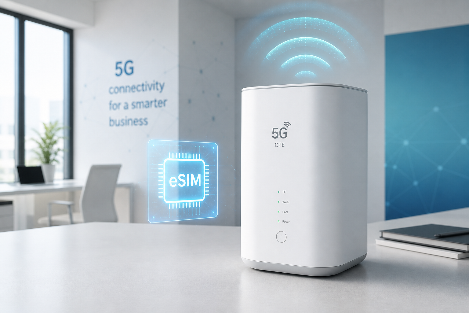
  • eSIM and iSIM Integration in 5G CPE Streamlines Global B2B FWA Deployments as Embedded SIM Technology Eliminates Physical SIM Logistics for Enterprise Customers in 2026

    eSIM and iSIM Integration in 5G CPE Streamlines Global B2B FWA Deployments as Embedded SIM Technology Eliminates Physical SIM Logistics for Enterprise Customers in 2026

    The global enterprise Fixed Wireless Access (FWA) market is projected to surpass $18 billion by 2027, with multinational deployments becoming the norm rather than the exception. Yet beneath the surface of this growth lies a persistent operational challenge that has plagued B2B CPE rollouts for years: physical SIM card management across borders, carriers, and regulatory domains.

    Enter eSIM (embedded SIM) and iSIM (integrated SIM) technology. These two related but distinct standards are fundamentally reshaping how enterprises procure, deploy, and manage 5G CPE at global scale — eliminating a logistics bottleneck that has long been accepted as an unavoidable cost of doing business.

    The Physical SIM Problem at Enterprise Scale

    For B2B deployments spanning multiple countries, traditional physical SIM cards introduce a cascade of operational inefficiencies. A typical multinational retailer deploying 5G CPE across 500 locations in 12 countries must contend with at least 12 different carrier SIM variants, each with its own procurement cycle, shipping logistics, regional regulatory compliance, and activation workflow.

    The numbers are sobering. Industry estimates suggest that physical SIM logistics — procurement, secure warehousing, international shipping, on-site insertion, and decommissioning — can add $15–$35 per device to the total cost of ownership. For a 10,000-unit enterprise deployment, that translates to $150,000–$350,000 in pure logistics overhead before a single byte of data flows through the network.

    Beyond cost, physical SIMs introduce security vulnerabilities. A SIM card that is shipped separately from the CPE can be intercepted, cloned, or tampered with during transit. In regulated industries — finance, healthcare, critical infrastructure — this represents an unacceptable attack surface.

    eSIM: Software-Defined Carrier Selection

    The GSMA-standardized eSIM (eUICC) architecture decouples the SIM profile from the physical form factor. Instead of inserting a physical card, the CPE contains a soldered eUICC chip that can be remotely provisioned with operator profiles via the GSMA’s Remote SIM Provisioning (RSP) infrastructure.

    For B2B deployments, this creates a fundamentally different operational model. A single 5G CPE SKU can be manufactured, warehoused, and shipped to any country without pre-assigning a carrier. The operator profile is downloaded over-the-air upon first boot — or even switched mid-lifecycle if the enterprise changes carriers or adds multi-carrier failover.

    Key technical capabilities enabled by eSIM in 5G CPE include:

    • Multi-Profile Storage: Modern eUICC chips can store multiple operator profiles simultaneously, enabling carrier-agnostic deployments where the CPE can switch between providers based on signal quality, cost, or policy.
    • Zero-Touch Provisioning: Combined with TR-369 USP or proprietary ACS platforms, eSIM enables true zero-touch onboarding where CPE devices self-configure upon power-up without any on-site technician involvement.
    • Remote Carrier Switching: Enterprises can remotely migrate an entire fleet from one carrier to another — for example, when renegotiating contracts or when a new operator builds out coverage in a target region — without physically touching any device.
    • Regulatory Compliance Automation: eSIM profiles can be pre-vetted for compliance with local telecom regulations (IMEI registration requirements, lawful intercept obligations), reducing customs delays and regulatory friction at border crossings.

    iSIM: The Next Integration Frontier

    While eSIM is now mainstream — GSMA reports over 400 operator eSIM launches globally as of mid-2026 — iSIM (integrated SIM) represents the next evolutionary step. The iSIM architecture embeds the SIM functionality directly into the CPE’s system-on-chip (SoC), eliminating the need for a separate eUICC component entirely.

    Qualcomm’s Snapdragon X75 and X80 modem-RF platforms, as well as MediaTek’s T800 series, now include native iSIM support with GSMA SAS-UP certification. For CPE manufacturers, this integration delivers several advantages:

    • Bill of Materials Reduction: Eliminating the discrete eUICC chip reduces component count, PCB real estate requirements, and supply chain complexity — particularly meaningful for compact CPE form factors like 5G mobile hotspots and outdoor FWA units.
    • Power Efficiency: iSIM implementations in advanced SoC nodes (4nm and below) consume approximately 40–60% less power than discrete eUICC solutions, contributing to longer battery life in portable CPE and reduced thermal load in fixed installations.
    • Enhanced Security Posture: iSIM leverages the SoC’s existing hardware root of trust and secure enclave, creating a more tightly integrated security architecture that is harder to physically attack than a discrete chip on the PCB.
    • Simplified Certification: With iSIM functionality pre-certified as part of the modem platform, CPE manufacturers can reduce the carrier certification cycle by 4–8 weeks per operator.

    Real-World B2B Deployment Models

    Several deployment patterns are emerging as eSIM/iSIM-capable 5G CPE reaches commercial maturity:

    Multinational Retail SD-WAN: A global retailer deploys identical 5G CPE hardware across 30 countries. Each unit boots, detects its location via network-based geolocation, and downloads the appropriate local carrier profile via RSP. The CPE then establishes an SD-WAN tunnel to the nearest cloud on-ramp, providing uniform policy enforcement regardless of the underlying carrier.

    Cross-Border Fleet Telematics: Logistics companies operating across the EU, ASEAN, or USMCA trade zones use iSIM-equipped 5G CPE in vehicles that automatically switch carrier profiles at border crossings. The CPE maintains session continuity using make-before-break profile switching, avoiding the data session drops that plague physical SIM-based solutions.

    Global IoT Backhaul: Agricultural technology providers deploying sensor networks across multiple continents use eSIM-enabled outdoor 5G CPE as aggregation gateways. A single hardware SKU serves deployments in Brazil, Kenya, India, and Australia — each downloading the appropriate regional carrier profile during installation by local technicians with no SIM logistics overhead.

    Enterprise Procurement Impact

    The shift to eSIM/iSIM is reshaping B2B CPE procurement in three fundamental ways:

    1. SKU Rationalization: Instead of maintaining region-specific CPE variants with different SIM configurations, enterprises can standardize on a single global SKU. This reduces procurement complexity, enables volume pricing, and simplifies sparing strategies.

    2. Just-in-Time Carrier Selection: Carrier decisions can be deferred until the moment of deployment — or even changed afterward. This shifts bargaining power toward the enterprise, enabling competitive carrier selection based on real-time pricing and performance data.

    3. Reduced Deployment Timelines: Physical SIM procurement and shipping adds 2–6 weeks to typical enterprise deployment timelines. eSIM eliminates this entirely, enabling same-week deployment from local inventory.

    Challenges and Considerations

    Despite the clear advantages, several challenges must be addressed for successful eSIM/iSIM CPE deployments:

    • RSP Infrastructure Maturity: While GSMA RSP standards are well-defined, not all carriers have fully deployed the required SM-DP+ (Subscription Manager Data Preparation) infrastructure. Enterprises should verify RSP readiness with target carriers before committing to eSIM-only deployments.
    • Regulatory Fragmentation: Some countries maintain restrictions on permanent roaming or remote SIM provisioning. India, for example, required amendments to its M2M guidelines before permitting eSIM for IoT devices. Enterprises must navigate this regulatory patchwork on a country-by-country basis.
    • Profile Lifecycle Management: At scale, managing thousands of eSIM profiles — including provisioning, suspension, reactivation, and deletion — requires robust integration between the enterprise’s device management platform and carrier SM-DP+ systems.
    • eSIM/iSIM Transition Strategy: For enterprises with existing fleets of physical SIM-based CPE, a phased migration approach is recommended. New deployments adopt eSIM/iSIM; existing devices are migrated during natural refresh cycles rather than through costly retrofits.

    Outlook: 2026–2028

    The trajectory is clear. GSMA Intelligence projects that by 2028, over 70% of new 5G CPE shipped for enterprise FWA will incorporate eSIM or iSIM technology. The convergence of GSMA SGP.32 (IoT eSIM standard) with 3GPP Release 18 enhancements for non-terrestrial network integration will further expand the addressable use cases.

    For B2B buyers and systems integrators, the message is straightforward: eSIM and iSIM are no longer emerging technologies — they are current-generation procurement requirements. Organizations that incorporate embedded SIM capabilities into their 5G CPE RFPs today will realize compounding operational savings over the 3–5 year lifecycle of their deployed fleets.

    The era of shipping plastic SIM cards across borders for enterprise network deployments is rapidly drawing to a close. For the B2B 5G CPE market, that is unequivocally good news.

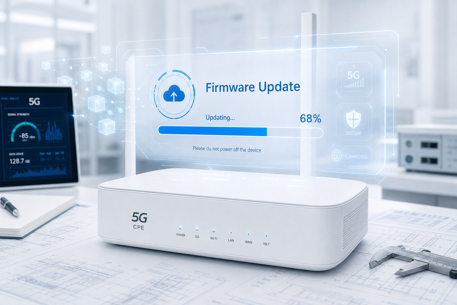
  • 5G CPE Firmware Over-the-Air Update Architecture: Delta OTA, A/B Slot Fallback Mechanisms, and Fleet-Scale FOTA Security Best Practices for B2B Deployments

    5G CPE Firmware Over-the-Air Update Architecture: Delta OTA, A/B Slot Fallback Mechanisms, and Fleet-Scale FOTA Security Best Practices for B2B Deployments

    As enterprise 5G CPE deployments scale from hundreds to tens of thousands of distributed gateways, the ability to securely and reliably update device firmware over the air becomes a critical operational capability. This technical deep-dive examines the firmware over-the-air (FOTA) update architectures being adopted by leading CPE manufacturers and network operators in 2026, covering delta update mechanisms, A/B slot fallback strategies, cryptographic security frameworks, and fleet-scale update orchestration best practices that B2B buyers should evaluate when selecting 5G CPE platforms.

    Why FOTA Architecture Matters for Enterprise CPE Deployments

    In traditional enterprise networking, firmware updates were infrequent events — often deferred until the next scheduled maintenance window, which could be months away. The 5G CPE landscape has fundamentally changed this operational model. With 3GPP specifications evolving through biannual Release cycles, operator network feature rollouts introducing new RAN capabilities, and the expanding attack surface of always-connected cellular gateways requiring regular security patches, B2B CPE deployments now require firmware update cadences measured in weeks rather than quarters.

    The stakes are high. A poorly executed firmware update that bricks devices, introduces regressions, or creates security vulnerabilities can disrupt connectivity for hundreds or thousands of enterprise sites simultaneously. Industry analysis indicates that CPE firmware-related outages account for approximately 31% of enterprise FWA service disruptions, making FOTA reliability a direct determinant of service availability and customer satisfaction.

    Delta Update Mechanisms: Minimizing Bandwidth and Downtime

    Full-image firmware updates, where the entire firmware binary (typically 128-512 MB for modern 5G CPE devices) is downloaded and flashed, impose significant operational costs at fleet scale. A fleet of 10,000 CPE devices receiving a 256 MB full-image update consumes approximately 2.5 TB of cumulative cellular data — representing substantial bandwidth costs and, in regions with data caps, potential service throttling.

    Delta OTA (differential update) technology addresses this challenge by transmitting only the binary differences between the currently installed firmware version and the target version. Modern delta update engines, based on algorithms such as bsdiff, Courgette, or vendor-proprietary implementations, achieve compression ratios of 70-95% compared to full-image updates. A 256 MB firmware image may be delivered as a delta package of just 15-75 MB, dramatically reducing cellular data consumption and update download time.

    Key technical considerations for delta update implementations include:

    Block-Level Differencing: The delta engine operates at the block or sector level, comparing cryptographic hashes of firmware partitions between source and target versions. Only modified blocks are included in the delta package, with the on-device update agent reconstructing the target image by applying patches to existing blocks in place, minimizing temporary storage requirements on resource-constrained CPE hardware.

    Multi-Version Delta Chains: In heterogeneous fleets where devices may be running multiple different firmware versions (due to staged rollouts, regional variants, or missed previous updates), the FOTA server must either generate and store delta packages for every possible source-to-target version pair, or implement a delta chain mechanism where the device sequentially applies multiple deltas to reach the target version. Leading FOTA platforms now support adaptive delta generation, where the server computes the optimal delta path based on the device’s current version at update time, balancing package size against update complexity.

    Compressed Delta Delivery: Delta packages are typically further compressed using LZMA2 or Zstandard algorithms before transmission, achieving an additional 20-40% size reduction beyond the differential compression. The update agent decompresses the package in a streaming fashion during application, avoiding the need to store both the compressed package and uncompressed delta simultaneously in device memory.

    A/B Slot Fallback Architecture: Ensuring Update Safety at Scale

    The A/B (dual-bank) firmware architecture, originally pioneered by Google for Android OS updates and now widely adopted in embedded cellular devices, provides a robust mechanism for safe firmware updates with automatic rollback capability. In an A/B CPE, the device maintains two complete firmware partitions (Slot A and Slot B), with only one slot active at any given time.

    The A/B update process follows a deterministic seven-step sequence:

    1. Status Check: The FOTA server queries the device for current active slot, firmware version, and slot health status.
    2. Delta Download: The delta update package targeting the inactive slot is downloaded to the device via HTTPS, with integrity verified through checksum validation.
    3. Inactive Slot Patching: The update agent applies the delta to the inactive slot’s firmware partition while the device continues normal operation on the active slot — a critical advantage that eliminates service downtime during the update application phase.
    4. Post-Apply Verification: The patched inactive slot undergoes cryptographic integrity verification (SHA-256 hash comparison against the expected target image) and, optionally, a simulated boot test.
    5. Slot Switch and Reboot: The bootloader is instructed to switch the active slot designation and the device reboots into the newly updated firmware. Typical reboot time is 45-90 seconds for embedded CPE devices.
    6. Post-Boot Health Check: Upon booting into the updated slot, the device executes a predefined health verification sequence: confirming WAN connectivity establishment, validating that core services (routing, DHCP, DNS proxy) are operational, and reporting health status to the FOTA management platform.
    7. Commit or Rollback: If all health checks pass within a configurable timeout window (typically 5-15 minutes), the update is committed and the previous slot is marked as the new inactive slot. If any health check fails, the bootloader automatically reverts to the previous firmware slot on the next reboot.

    The A/B architecture provides several critical safety guarantees for enterprise CPE deployments. The most important is guaranteed recoverability: even if the new firmware image is completely non-functional (kernel panic, persistent boot loop, or radio initialization failure), the device can always fall back to the known-good previous firmware version. This eliminates the risk of “bricked” devices requiring physical access for recovery — an essential characteristic for CPE gateways deployed at unmanned remote sites, rooftop installations, or geographically distributed enterprise branch locations.

    FOTA Security Architecture: Cryptographic Protections for the Update Pipeline

    The firmware update pipeline represents one of the most security-critical attack surfaces in any connected device. A compromised update mechanism can be exploited to install persistent malware, establish backdoor access, or recruit devices into botnets. The following security controls should be mandatory requirements in any B2B CPE procurement:

    Secure Boot and Hardware Root of Trust

    The CPE must implement a hardware root of trust (HRoT) — typically a dedicated secure element or TPM 2.0-compliant chip — that anchors the entire boot and update chain. The HRoT stores an immutable public key (or hash of a public key) that the first-stage bootloader (boot ROM) uses to verify the signature of the second-stage bootloader. This verification chain extends through the OS kernel to the application firmware, ensuring that only cryptographically authenticated code executes on the device. Any firmware image that fails signature verification at any stage in the chain is rejected, preventing unauthorized or tampered firmware from being installed.

    Firmware Image Signing

    All firmware images (both full images and delta packages) must be digitally signed by the manufacturer or authorized operator using asymmetric cryptography (RSA-3072 or ECDSA P-384 minimum). The device verifies signatures before applying any update, using a public key that is itself protected by the secure boot chain. This prevents attackers from delivering malicious firmware even if they compromise the FOTA distribution server or man-in-the-middle the update download.

    TLS 1.3 with Mutual Authentication

    All FOTA communications between CPE devices and update servers must use TLS 1.3 with mutual (mTLS) authentication. The CPE presents a device certificate (provisioned at manufacturing and stored in the secure element) to authenticate itself to the FOTA server, while the server presents its certificate for device-side verification. This bidirectional authentication prevents both rogue devices from accessing the update infrastructure and rogue servers from delivering updates to legitimate devices.

    Rollback Protection

    To prevent attackers from exploiting known vulnerabilities by downgrading devices to older, vulnerable firmware versions, the CPE must implement anti-rollback protection. The secure element maintains a minimum acceptable firmware version counter that is incremented with each update and cannot be decremented. Any firmware image with a version number below this counter is rejected, even if it carries a valid cryptographic signature.

    Fleet-Scale Update Orchestration Strategies

    Managing FOTA operations across a fleet of thousands of geographically distributed CPE devices introduces significant orchestration complexity. Best practices for fleet-scale update management include:

    Canary Deployments: Rather than pushing updates to the entire fleet simultaneously, operators should deploy to a small “canary” cohort (typically 1-5% of devices, selected to represent diverse hardware revisions, firmware baseline versions, and network conditions). The canary cohort is monitored for 24-72 hours post-update to detect regressions before broader rollout. Only after canary health metrics meet predefined thresholds is the update expanded to the full fleet.

    Geographic and Topological Grouping: Updates should be deployable to device groups defined by geographic region, customer tenant, hardware revision, or network topology. This enables operators to sequence updates in a manner that minimizes correlated failure risk — for example, updating devices at different customer sites in staggered phases rather than simultaneously.

    Time-Windowed Scheduling: Enterprise CPE updates should be schedulable within customer-defined maintenance windows to avoid disrupting business-critical operations. The FOTA platform must support timezone-aware scheduling with configurable blackout periods (e.g., “do not update between 08:00-18:00 local time on weekdays”) and the ability for enterprise administrators to approve or defer update windows through a self-service portal.

    Bandwidth-Aware Throttling: At fleet scale, simultaneous update downloads from thousands of devices can overwhelm FOTA server infrastructure and enterprise WAN links. Intelligent update orchestration platforms implement token-bucket or leaky-bucket rate limiting, randomized download start times within update windows, and peer-to-peer update distribution (where CPE devices at the same site share downloaded packages via local LAN) to manage bandwidth consumption.

    Honlly Telecom’s FOTA Capabilities

    Honlly Telecom’s 5G CPE platforms incorporate industry-leading FOTA capabilities designed for enterprise-scale deployments. Our devices feature A/B slot firmware architecture with hardware root of trust anchored in TPM 2.0-compliant secure elements, delta update support achieving typical 80-90% compression ratios, and comprehensive remote management APIs that integrate with leading operator device management platforms including TR-369 USP (User Services Platform) and LwM2M.

    For B2B buyers and operator partners managing large CPE fleets, Honlly provides a cloud-based FOTA orchestration platform supporting canary deployment workflows, geographic grouping, time-windowed scheduling, and real-time fleet health dashboards. Our engineering team works closely with enterprise customers to design FOTA strategies that align with their operational requirements and risk tolerance profiles.

    Conclusion

    Firmware over-the-air update capability is not merely a convenience feature for enterprise 5G CPE deployments — it is a fundamental operational necessity that directly impacts service reliability, security posture, and total cost of ownership. B2B buyers evaluating CPE platforms should rigorously assess FOTA architecture across the dimensions discussed in this guide: delta update efficiency, A/B slot recoverability, cryptographic security of the update pipeline, and fleet-scale orchestration capabilities. A CPE device with excellent RF performance but inadequate FOTA infrastructure will inevitably generate operational burden and security risk that undermines its initial performance advantages. In the enterprise 5G era, the quality of a CPE platform’s update architecture is as important as the quality of its radio.

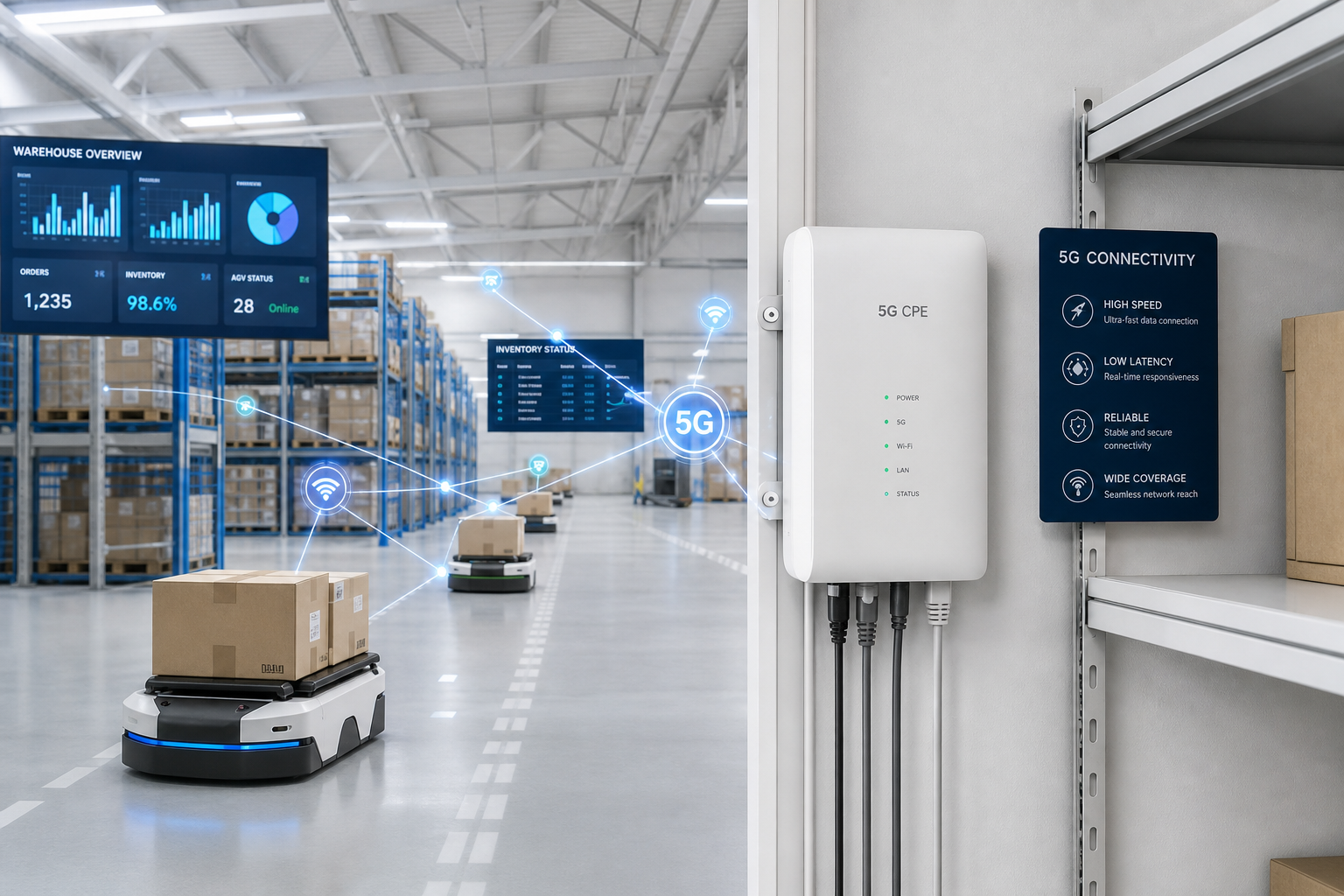
  • A Technical Buyer’s Guide to 5G CPE for Smart Warehousing and Logistics: AGV Connectivity, Real-Time Inventory Tracking, and Industrial-Grade Reliability for 2026

    A Technical Buyer’s Guide to 5G CPE for Smart Warehousing and Logistics: AGV Connectivity, Real-Time Inventory Tracking, and Industrial-Grade Reliability for 2026

    As warehouse automation accelerates across global supply chains, the connectivity infrastructure supporting automated guided vehicles (AGVs), autonomous mobile robots (AMRs), real-time inventory systems, and IoT sensor networks has become a mission-critical component of logistics operations. This comprehensive technical buyer’s guide examines how 5G CPE solutions are being deployed in smart warehousing environments, the key technical specifications procurement teams should evaluate, and the integration architectures that enable seamless Industry 4.0 logistics operations throughout 2026 and beyond.

    The Warehousing Connectivity Challenge

    Modern warehouses present one of the most demanding RF environments in enterprise networking. Steel racking systems create multipath interference and signal shadowing; high-bay storage configurations introduce vertical coverage challenges spanning 12-15 meters; and the density of connected devices — often exceeding 500-2,000 endpoints per 10,000 square meters — strains conventional Wi-Fi architectures. Meanwhile, the mobility patterns of AGVs and AMRs, which traverse the facility at speeds of 1.5-2.5 meters per second, require seamless handover with sub-50ms interruption tolerance to maintain operational safety and productivity.

    Traditional Wi-Fi 6/6E networks, while cost-effective for office environments, struggle to deliver consistent performance in these challenging conditions. Channel congestion, co-channel interference, and the fundamental limitations of unlicensed spectrum create reliability gaps that directly translate into operational downtime. Industry data suggests that warehouse connectivity failures cost large distribution centers an average of $12,000-$18,000 per hour in lost productivity, making connectivity reliability a direct bottom-line concern for logistics operators.

    5G-based private and hybrid network solutions, anchored by industrial-grade CPE gateways, are emerging as the preferred connectivity architecture for next-generation smart warehouses. The combination of licensed spectrum reliability, deterministic latency through URLLC capabilities, and support for massive device density makes 5G uniquely suited to the warehousing use case.

    Critical 5G CPE Specifications for Warehouse Deployments

    When evaluating 5G CPE solutions for warehouse environments, technical buyers should prioritize the following specifications:

    1. RF Performance and Antenna Architecture

    Warehouse CPE devices must deliver consistent RF performance across challenging propagation conditions. Key requirements include 4×4 MIMO on sub-6 GHz bands with antenna isolation exceeding 15dB, support for external antenna connections (SMA or N-type connectors) for installations in RF-shielded locations, and beamforming capabilities that can dynamically adapt to changing RF environments as racking configurations and inventory positions shift. For facilities with extensive metal infrastructure, CPE devices supporting antenna diversity and polarization diversity provide measurable improvements in link reliability.

    2. Device Density and Concurrent Connection Handling

    A single 5G CPE gateway in a warehouse environment may serve as the backhaul aggregation point for 50-200 locally connected devices including barcode scanners, RFID readers, environmental sensors, IP cameras, and worker mobile terminals. The CPE must support minimum 128 concurrent Wi-Fi client associations on the LAN side (preferably Wi-Fi 6 or Wi-Fi 7), with effective airtime fairness and QoS mechanisms that prevent low-priority IoT traffic from starving mission-critical AGV control streams. On the WAN side, the 5G modem should maintain stable connections under high PDU session counts, supporting simultaneous communication with multiple network slices for traffic segregation.

    3. Latency and Handover Performance

    AGV and AMR control systems typically require sub-20ms end-to-end latency for real-time navigation and collision avoidance. CPE devices must support 5G URLLC features with configured grant scheduling and mini-slot transmission to achieve consistent low-latency performance. Equally critical is handover behavior: as a CPE mounted on a mobile asset moves between gNB coverage zones, the device must execute make-before-break handovers with interruption times below 5ms to prevent navigation system timeouts.

    4. Industrial Ruggedization

    Warehouse environments expose networking equipment to dust, vibration, temperature fluctuations, and occasional impacts from material handling equipment. CPE devices should carry minimum IP51 ingress protection (preferably IP54 or higher for dusty environments), operate reliably across a -10°C to +55°C temperature range, and feature shock-resistant mounting brackets. For cold storage and freezer warehouse applications (-25°C to -5°C), specialized CPE variants with conformal coating and heated enclosures may be necessary to prevent condensation damage.

    Integration Architecture: 5G CPE in the Warehouse Technology Stack

    Effective warehouse deployments require seamless integration between 5G CPE gateways and the broader logistics technology ecosystem. The following architectural patterns have emerged as best practices:

    WMS and WCS Integration

    The Warehouse Management System (WMS) and Warehouse Control System (WCS) must be able to monitor CPE connectivity status and incorporate network health metrics into operational decision-making. Modern CPE devices expose RESTful APIs and SNMP v3 interfaces that enable WMS platforms to query real-time signal quality, throughput, and connected device counts. When CPE metrics indicate degraded RF conditions in a particular warehouse zone, the WCS can proactively reroute AGV traffic to alternative paths, avoiding connectivity blackspots before they cause disruptions.

    RFID and Barcode System Connectivity

    Fixed RFID portal readers and conveyor-mounted barcode scanners generate high-frequency, low-payload data streams that must be reliably backhauled to inventory management systems. 5G CPE gateways should support protocol translation and edge processing capabilities that aggregate RFID tag reads locally, filter duplicate reads, and transmit consolidated inventory events to the central WMS — reducing backhaul bandwidth consumption by 60-80% compared to raw data forwarding approaches.

    Video Surveillance and AI Analytics

    Modern warehouses deploy IP camera networks for security, safety compliance, and AI-powered operational analytics (dock door utilization monitoring, package dimensioning, damage detection). Each 4K camera stream requires 15-25 Mbps of sustained uplink bandwidth. 5G CPE gateways with integrated edge AI processing can execute video analytics locally, transmitting only metadata and alert events to central systems — a critical capability for warehouses with limited WAN bandwidth or data sovereignty requirements.

    Deployment Topology Options

    Smart warehouse 5G deployments typically follow one of three topologies:

    Private 5G Network: The warehouse operates a dedicated 5G RAN and core network using locally licensed or shared spectrum (e.g., n77, n78, or n48 CBRS band in applicable regions). CPE devices connect exclusively to the private network, providing complete control over QoS policies, security posture, and data locality. This topology is preferred by large enterprise logistics operators with the capital budget and technical expertise to manage private cellular infrastructure.

    Hybrid Public-Private with Network Slicing: The CPE connects to a public operator’s 5G network with a dedicated network slice provisioned for warehouse operations. This approach combines the coverage and reliability of carrier-grade infrastructure with slice-level isolation and QoS guarantees, making it attractive for mid-market logistics providers that cannot justify the investment in full private network deployment.

    Dual-SIM Failover Architecture: CPE gateways equipped with dual SIM slots connect to two independent operator networks, providing automatic failover in the event of a primary network outage. This topology is commonly deployed in 24/7 distribution centers where any connectivity interruption directly impacts order fulfillment SLAs and customer commitments.

    Honlly Telecom Solutions for Smart Warehousing

    Honlly Telecom’s industrial 5G CPE portfolio includes solutions specifically engineered for warehouse and logistics environments. Our gateways feature ruggedized enclosures rated for industrial deployment conditions, 4×4 MIMO antenna configurations with external antenna support, and comprehensive device management capabilities that enable centralized monitoring and configuration of distributed CPE fleets across multiple warehouse locations.

    For logistics operators planning 5G-enabled warehouse transformations, Honlly offers pre-deployment site survey support, integration engineering assistance, and ongoing technical support to ensure successful project outcomes. Contact our B2B solutions team to discuss your specific warehousing connectivity requirements.

    Procurement Checklist for B2B Buyers

    When issuing RFPs for warehouse 5G CPE solutions, include the following evaluation criteria:

    • Supported 5G bands (ensure coverage of locally available spectrum, including private network bands)
    • 4×4 MIMO support on all target bands with external antenna connectivity
    • Minimum 128 concurrent Wi-Fi client associations (Wi-Fi 6 or later)
    • URLLC support for sub-20ms latency on AGV/AMR control traffic
    • IP54 or higher ingress protection rating with -10°C to +55°C operating range
    • Dual SIM with automatic failover for high-availability deployments
    • RESTful management API and SNMP v3 for WMS/WCS integration
    • Edge compute capability for local RFID filtering and video analytics processing
    • Centralized fleet management platform with bulk configuration and OTA update support
    • Vendor-provided deployment engineering support and site survey services

    By systematically evaluating CPE solutions against these criteria, procurement teams can ensure their selected 5G gateway platform delivers the reliability, performance, and integration capability required for demanding warehouse automation environments in 2026 and beyond.

  • 5G CPE and Multi-Access Edge Computing Convergence Opens New B2B Revenue Streams as Enterprise Edge Applications Drive Demand for Sub-10ms Latency Gateways in 2026

    5G CPE and Multi-Access Edge Computing Convergence Opens New B2B Revenue Streams as Enterprise Edge Applications Drive Demand for Sub-10ms Latency Gateways in 2026

    The global B2B telecommunications landscape is witnessing a transformative convergence as 5G Customer Premises Equipment (CPE) and Multi-Access Edge Computing (MEC) increasingly operate as an integrated platform rather than discrete network layers. Throughout the second half of 2026, leading network operators and enterprise solution providers are accelerating the deployment of edge-native 5G CPE gateways capable of hosting containerized workloads at the network edge, fundamentally reshaping how enterprises consume and monetize connectivity services.

    The Convergence Imperative: Why CPE and Edge Computing Are Merging

    The traditional model of enterprise networking positioned the CPE as a simple WAN termination device — a box that converted cellular signals into Ethernet packets and forwarded them to the corporate LAN. Edge computing, meanwhile, was treated as a separate infrastructure layer residing in carrier facilities, colocation data centers, or on-premises server racks. This architectural separation imposed inherent latency penalties: even with 5G’s improved air interface, applications requiring sub-10ms response times struggled when compute resources sat multiple network hops away from the access point.

    The convergence of CPE and MEC addresses this gap directly. Modern 5G CPE gateways are now being designed with embedded compute capabilities — ARM-based multi-core processors, hardware-accelerated AI inference engines, and SSD storage — enabling them to function as micro-edge nodes. This architectural shift means that latency-sensitive enterprise applications such as real-time video analytics, industrial machine vision, autonomous mobile robot (AMR) coordination, and augmented reality (AR) assisted maintenance can execute directly on the CPE device rather than traversing back to a centralized cloud or even a regional edge data center.

    Industry analysts project that edge-capable 5G CPE shipments will exceed 12 million units globally by Q4 2026, representing a 47% year-over-year increase. The driving force is clear: enterprises deploying private 5G networks and fixed wireless access (FWA) solutions increasingly demand that connectivity infrastructure doubles as a distributed compute fabric, reducing both latency and backhaul costs while enabling new revenue-generating edge services.

    Operator Strategies: From Connectivity Provider to Edge Platform Orchestrator

    For telecommunications operators, the CPE-MEC convergence presents a strategic opportunity to move beyond the commoditized connectivity market. Major carriers across Europe, Asia-Pacific, and North America are deploying edge-enabled CPE platforms that support Kubernetes-based container orchestration, allowing third-party ISVs and enterprise developers to deploy applications directly onto customer-premises gateways.

    Vodafone’s recently expanded Edge Innovation Programme now incorporates application-hosting CPE devices as part of its distributed MEC architecture, targeting manufacturing quality inspection and retail footfall analytics use cases. Deutsche Telekom’s Campus Edge solution integrates 5G CPE gateways with on-premises edge compute nodes, offering enterprises a unified platform for private 5G connectivity and localized application processing. In the Asia-Pacific region, Singtel’s Paragon edge orchestration platform has added CPE-level application deployment capabilities, enabling enterprises to run AI inference workloads at the network access layer.

    This shift is reshaping operator revenue models. Rather than billing solely for bandwidth and SIM subscriptions, carriers are introducing tiered edge service packages that bundle connectivity, compute resources, and pre-integrated enterprise applications. Analysts estimate that edge services can increase average revenue per enterprise account (ARPA) by 35-60% compared to connectivity-only offerings, making the CPE-MEC convergence one of the most significant B2B monetization opportunities in the 5G era.

    Key Enabling Technologies: What Makes Edge-Capable CPE Possible

    Several technological advancements have converged to make CPE-level edge computing commercially viable in 2026:

    Advanced System-on-Chip (SoC) Platforms: Next-generation CPE chipsets from Qualcomm (Snapdragon X75/X80 series), MediaTek (T830 platform), and others now integrate dedicated AI processing units (APUs) and multi-core CPU clusters capable of handling concurrent connectivity and application workloads. These SoCs deliver 8-15 TOPS of AI inference performance while maintaining power envelopes suitable for fanless CPE enclosures.

    Lightweight Container Runtimes: The adoption of micro-VM technologies such as AWS Firecracker and lightweight Kubernetes distributions (K3s, MicroK8s) enables secure, isolated application execution on resource-constrained CPE hardware. These runtimes provide strong workload isolation without the overhead of full virtual machines, making multi-tenant edge application hosting practical on gateway devices.

    5G LAN-Type Services and URLLC: 3GPP Release 18 enhancements to 5G LAN-type services enable direct Layer 2 connectivity between CPE-hosted applications and on-premises industrial equipment, bypassing complex routing configurations. Combined with Ultra-Reliable Low-Latency Communication (URLLC) capabilities, these features ensure deterministic connectivity for time-sensitive edge applications.

    Zero-Touch Edge Orchestration: GSMA-compliant eSIM provisioning combined with cloud-native device management platforms enables operators to remotely deploy, configure, and manage edge applications across thousands of distributed CPE gateways without on-site intervention. This zero-touch operational model is critical for achieving the scale economics required for widespread CPE-MEC adoption.

    Enterprise Use Cases Driving Adoption

    The business case for CPE-MEC convergence is being validated across multiple industry verticals:

    Manufacturing and Industry 4.0: Edge-capable 5G CPE gateways deployed on factory floors execute real-time machine vision inspection algorithms directly at the access point, eliminating the round-trip latency to centralized servers. A major automotive manufacturer in Germany recently deployed edge-CPE units across 14 production facilities, achieving 98.7% defect detection accuracy with under 8ms processing latency — a 40% improvement over cloud-based inspection systems.

    Smart Retail and Frictionless Commerce: Retail chains are deploying edge-CPE devices to run computer vision-based shopper analytics, shelf inventory monitoring, and autonomous checkout applications. By processing video feeds locally on the CPE, retailers avoid the bandwidth costs and privacy concerns associated with streaming sensitive footage to external cloud services.

    Logistics and Supply Chain: Distribution centers use edge-enabled CPE gateways to coordinate autonomous mobile robots, process RFID tag reads in real time, and optimize warehouse management system (WMS) workflows. The localized compute capability ensures uninterrupted operations even during WAN connectivity disruptions — a critical requirement for 24/7 logistics facilities.

    Honlly Telecom’s Edge-Ready CPE Portfolio

    As a leading B2B 5G CPE manufacturer, Honlly Telecom is actively developing edge-capable gateway solutions aligned with the CPE-MEC convergence trend. Our engineering teams are integrating advanced SoC platforms with container runtime support, enabling our enterprise customers and operator partners to deploy edge applications alongside high-performance 5G connectivity from a single, unified hardware platform.

    Honlly’s edge-ready CPE solutions feature multi-core ARM processors with dedicated AI acceleration, support for standard container orchestration frameworks, and comprehensive remote device management capabilities. These gateways are designed to serve as the foundational node in distributed edge architectures, enabling B2B customers to extract maximum value from their 5G infrastructure investments.

    For more information about Honlly Telecom’s 5G CPE solutions and edge computing capabilities, contact our B2B sales team or visit our product catalog.

    Conclusion

    The convergence of 5G CPE and Multi-Access Edge Computing represents a paradigm shift in enterprise networking architecture. As CPE devices evolve from passive connectivity endpoints into active edge compute nodes, operators gain new B2B monetization pathways, enterprises achieve lower latency and reduced backhaul costs, and the broader 5G ecosystem moves closer to realizing the full promise of distributed intelligence at the network edge. For B2B buyers evaluating 5G CPE investments in 2026 and beyond, edge compute capability should be a core evaluation criterion alongside traditional metrics such as throughput, band support, and ruggedization — the gateway that connects your enterprise today may also power its edge applications tomorrow.

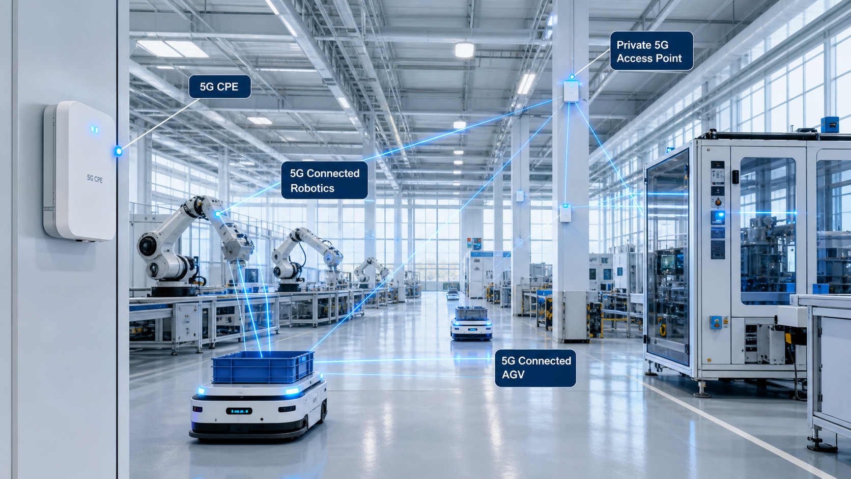
  • Private 5G Network Deployments Surge Across Global Manufacturing as Enterprises Deploy Dedicated CPE for Industry 4.0 and Smart Logistics in 2026

    Private 5G Network Deployments Surge Across Global Manufacturing as Enterprises Deploy Dedicated CPE for Industry 4.0 and Smart Logistics in 2026

    The private 5G network market is experiencing its most significant growth phase since the technology’s standardization, with enterprise deployments in manufacturing, logistics, and warehousing accelerating at an unprecedented pace through mid-2026. Industry analysts tracking private cellular adoption report that dedicated 5G networks — deployed and operated independently of public mobile network operators — now account for over 38% of industrial wireless infrastructure spending globally, up from 22% at the end of 2024. At the center of this expansion is a new class of purpose-built private 5G CPE designed specifically for industrial environments, marking a distinct departure from repurposed consumer FWA gateways that characterized early private network deployments.

    The Private 5G Value Equation for Industrial Enterprises

    Manufacturing organizations investing in private 5G cite three primary motivations that distinguish this technology from Wi-Fi 6E/7 and legacy industrial wireless alternatives. First, deterministic latency — the ability to guarantee sub-10ms end-to-end latency with 99.999% reliability — enables real-time closed-loop control for robotic workcells, automated guided vehicles (AGVs), and machine vision inspection systems that Wi-Fi cannot reliably support at scale. Second, coverage density — a single private 5G small cell can cover 50,000–100,000 square feet of factory floor space while maintaining reliable connectivity to thousands of endpoints, compared to the dozen or more Wi-Fi APs required for equivalent coverage with handoff complexity. Third, spectrum control — private 5G networks operating on dedicated spectrum (such as CBRS in the United States, n77/n78 globally, or locally licensed industrial spectrum) are immune to the co-channel interference and congestion that plague unlicensed Wi-Fi bands in dense industrial parks.

    The total cost of ownership analysis is increasingly favoring private 5G over wired Ethernet for new greenfield facilities. A mid-sized automotive components manufacturer in Bavaria reported that its private 5G deployment — covering 180,000 square feet with 12 small cells and 350 CPE endpoints — achieved a 41% reduction in network-related production downtime and a 28% decrease in cabling costs compared to its previous wired PROFINET infrastructure, with full ROI realized within 14 months of commissioning.

    CPE Architecture for Private 5G: Different Requirements, Different Silicone

    The CPE devices terminating private 5G networks differ fundamentally from their public-network counterparts across multiple engineering dimensions. Where public 5G FWA CPE prioritizes wide-area band support (n28, n71, n41, n77, n78, n79) and operator certification requirements, private 5G CPE optimizes for a narrower but more demanding set of industrial requirements that procurement teams should evaluate independently.

    Spectrum and Band Configuration: Private 5G CPE must support the specific spectrum bands allocated to the enterprise deployment, which may differ from public operator bands. In the United States, CBRS (n48, 3550–3700 MHz) is the dominant private 5G band, requiring CPE that supports Citizens Broadband Radio Service protocols including Spectrum Access System (SAS) compliance and Environmental Sensing Capability (ESC) coordination. In Europe, the n77 band (3.7–3.8 GHz for private networks) and n78 (3.8–4.2 GHz) require CPE with specific band lock and channel bandwidth configurations that may not be present in public-network devices. In Japan, the 4.6–4.9 GHz (n79) and 28 GHz (n257) bands serve private enterprise deployments with different propagation characteristics requiring band-optimized antenna designs.

    Industrial Protocol Integration: Unlike consumer FWA CPE that terminates at an Ethernet or Wi-Fi interface, private 5G CPE must integrate with industrial automation protocols at Layer 2 and above. PROFINET, EtherNet/IP, EtherCAT, Modbus TCP, and OPC UA are the lingua franca of factory floors, and private 5G CPE must transparently transport these protocols without introducing latency jitter or packet reordering that industrial controllers interpret as link failures. This requires CPE platforms with configurable QoS queue mapping (DSCP-to-5QI mapping), IEEE 802.1Qbv time-sensitive networking (TSN) support for deterministic scheduling, and frame preemption capability to ensure that critical industrial traffic is not delayed by best-effort data.

    Ruggedization and Form Factor: Factory-floor CPE must withstand vibration, dust, temperature extremes, and electromagnetic interference from welding equipment, variable-frequency drives, and induction heating systems. Industrial private 5G CPE typically carries IP65 or higher ingress protection, conformal-coated PCBs, and compliance with IEC 61000-6-2 (industrial EMC immunity) — specifications that consumer-grade devices never achieve. DIN-rail mounting, 24V DC industrial power input, and terminal-block I/O connectivity further differentiate industrial CPE from the desktop form factors common in FWA deployments.

    Smart Logistics and Warehousing: The Killer App

    While manufacturing was the early adopter vertical, logistics and warehousing is emerging as the volume driver for private 5G CPE. The combination of autonomous mobile robots (AMRs), high-definition video-based inventory scanning, wearable devices for pick-and-pack operations, and real-time location systems (RTLS) creates a connectivity density challenge that Wi-Fi struggles to meet.

    A single modern distribution center may operate 200+ AMRs simultaneously, each requiring 20–50 Mbps of reliable low-latency connectivity for LiDAR data streaming, path planning updates, and fleet coordination. Amazon Robotics, DHL Supply Chain, and Geek+ have all publicly discussed private 5G trials achieving AMR fleet densities 3–5× higher than Wi-Fi-based deployments, with robot-to-robot coordination latencies below 5ms enabling tighter vehicle spacing and higher warehouse throughput.

    The CPE requirements for logistics AMRs introduce additional engineering complexity: compact form factors suitable for vehicle mounting, power-over-Ethernet (PoE++) or direct vehicle power integration (12–48V DC), vibration and shock resistance per MIL-STD-810H, and seamless mobility across small cells as AMRs traverse facilities spanning hundreds of thousands of square feet. Handover interruption time must remain below 20ms to prevent AMR safety-stop events — a requirement that consumer CPE mobility implementations rarely satisfy.

    Core Network Architecture Choices

    Private 5G deployments in manufacturing and logistics face a strategic architectural decision: deploy an on-premises 5G core network or utilize a cloud-hosted or edge-hosted core-as-a-service. Each approach carries distinct implications for CPE selection and network design.

    On-Premises Core: A fully on-site 5G core (using platforms such as Druid Software Raemis, Athonet, or open-source Open5GS) provides maximum control, lowest latency (sub-millisecond core processing), and independence from external connectivity. CPE devices connect directly to the local User Plane Function (UPF), with all user traffic remaining within the facility’s network perimeter — a critical requirement for defense contractors, semiconductor fabs, and pharmaceutical manufacturers with data sovereignty constraints. The trade-off is higher upfront integration cost and the requirement for in-house 5G core expertise.

    Edge-Hosted Core-as-a-Service: Hyperscalers including AWS (AWS Private 5G), Microsoft (Azure Private 5G Core), and Google Cloud are now offering managed private 5G core services hosted at the edge. The CPE connects to a local UPF instance running on an on-premises edge compute node (AWS Outposts, Azure Stack Edge, or similar), with the control plane managed from the cloud. This approach reduces operational complexity while maintaining local traffic breakout for latency-sensitive industrial applications. CPE procurement for this model should verify integration certification with the specific hyperscaler’s private 5G platform.

    Spectrum Access Models by Region

    Procurement teams must navigate region-specific spectrum frameworks when specifying private 5G CPE:

    RegionPrimary Private 5G SpectrumLicensing ModelCPE Band Requirement
    United StatesCBRS (n48, 3550–3700 MHz)SAS-managed shared accessn48 with SAS/ESC protocol support
    Germany3.7–3.8 GHz (n77)Local licensing (BNetzA)n77 with configurable BW 10–100 MHz
    Japan4.6–4.9 GHz (n79) + 28 GHz (n257)Local licensing (MIC)n79 + optional n257 mmWave
    United Kingdomn77 (3.8–4.2 GHz) + shared accessOfcom local + shared accessn77/n78 with shared-access support
    Chinan41 (2.6 GHz) + n79 (4.9 GHz)Operator-leased industrial spectrumn41 + n79, carrier-specific config
    South Korean79 (4.7 GHz) + 28 GHzMSIT enterprise licensingn79 with operator coordination

    Procurement Framework for Private 5G CPE

    B2B buyers evaluating private 5G CPE for manufacturing and logistics should structure RFPs around the following evaluation criteria:

    1. Band and Spectrum Compliance (Critical): Verify CPE supports the exact bands, channel bandwidths, and spectrum access protocols (SAS, AFC, local license) required for the deployment country. Request factory test reports showing conducted and radiated RF performance on the target bands.
    2. Industrial Protocol Transport (Critical): Require documented validation of PROFINET, EtherNet/IP, OPC UA, and Modbus TCP transport over the 5G link with latency jitter measurements under load. TSN compliance (802.1Qbv, 802.1AS timing) should be verified if deterministic scheduling is required.
    3. 5G Core Interoperability (High): Confirm interoperability with the planned 5G core platform — whether on-premises (Druid, Athonet, Open5GS), hyperscaler (AWS, Azure, Google Cloud), or operator-managed. Request interoperability test reports or compatibility certification.
    4. Environmental Hardening (High): IP65 minimum for factory floor; IP67 for washdown areas. Operating temperature range should span -20°C to +60°C for unconditioned industrial spaces. Vibration and shock resistance should reference MIL-STD-810H or IEC 60068.
    5. Mobility Performance (High for Logistics): For AMR/AGV applications, request handover interruption time measurements at target vehicle speeds (1–5 m/s typical for warehouse AMRs). Sub-20ms interruption is the practical threshold for safety-critical mobile applications.
    6. Management and Orchestration (Medium): Private 5G CPE should support TR-369 USP for zero-touch provisioning, SNMPv3 for monitoring, and NETCONF/YANG for configuration management. Integration with the facility’s existing industrial network management system reduces operational overhead.
    7. Security Certification (Medium): For defense and critical infrastructure, verify FIPS 140-3 certification status, secure boot chain implementation, and hardware root of trust. IEC 62443-4-2 certification for industrial automation security is increasingly becoming a procurement requirement.

    Market Outlook: 2026–2028

    Industry forecasts project the global private 5G CPE market to reach $3.8 billion by 2028, growing at a compound annual rate exceeding 45%. Manufacturing and logistics together are expected to account for approximately 55% of private 5G CPE deployments by volume. The average selling price for industrial private 5G CPE is projected to decline from $450–650 (2025) to $250–350 (2028) as chipset volumes scale and competition intensifies — reaching a price point where private 5G becomes economically viable not just for Fortune 500 manufacturers but for mid-market enterprises operating single facilities.

    For B2B CPE distributors and system integrators, private 5G represents one of the highest-growth segments in the enterprise networking market. Enterprises deploying private networks require not just CPE hardware but comprehensive integration services, spectrum consulting, coverage planning, and ongoing managed services — creating a recurring revenue opportunity that extends well beyond the initial hardware sale. As 5G-Advanced (3GPP Release 18) features such as NR positioning, enhanced URLLC, and integrated sensing reach commercial maturity through 2027, the performance gap between private 5G and Wi-Fi in industrial environments will widen further, accelerating the adoption curve.

    This market analysis was prepared by the Honlly Telecom editorial team. For technical specifications of Honlly’s private 5G CPE portfolio or to discuss your industrial connectivity requirements, contact our enterprise solutions team at sales@xmhonlly.com.

  • A Technical Buyer’s Guide to 5G CPE for Retail Chains and Multi-Site SMBs: SD-WAN Integration, PCI-DSS Compliance, and Centralized Fleet Management for 2026

    A Technical Buyer’s Guide to 5G CPE for Retail Chains and Multi-Site SMBs: SD-WAN Integration, PCI-DSS Compliance, and Centralized Fleet Management for 2026

    Retail chains and multi-site small-to-medium businesses represent one of the largest addressable markets for 5G fixed wireless access, yet the specific technical requirements of distributed retail environments are frequently underserved by generic enterprise CPE platforms. A national quick-service restaurant chain operating 2,000 locations, or a regional pharmacy network with 150 branches, faces connectivity challenges that differ fundamentally from single-site enterprise deployments: mass deployment logistics, centralized configuration management, payment card industry compliance, and the need for consistent customer-facing Wi-Fi performance across every location. This technical buyer’s guide examines the CPE architecture, security, and management requirements that B2B procurement teams should specify when sourcing 5G CPE for retail and multi-site SMB deployments.

    The Multi-Site Connectivity Challenge

    Retail chains face a unique combination of operational requirements that consumer-grade broadband and basic enterprise routers cannot satisfy simultaneously. The typical retail location must support point-of-sale (POS) transaction processing requiring sub-2-second authorization latency with 99.99% uptime, PCI-DSS compliant network segmentation that isolates payment traffic from guest Wi-Fi and back-office operations, digital signage and in-store media requiring sustained 15–50 Mbps per display, and inventory management systems that synchronize multi-gigabyte databases across hundreds of locations during overnight batch windows. Simultaneously, customer-facing guest Wi-Fi — increasingly expected as a baseline amenity — must deliver satisfactory throughput to dozens of concurrent users without compromising the security or performance of business-critical transaction traffic.

    Traditional wired solutions — MPLS, business fiber, or carrier Ethernet — deliver the required reliability but at a per-site cost of $200–500 monthly for circuits that may take 60–90 days to provision. For chains opening 50–200 new locations annually, this provisioning timeline creates a direct revenue gap: each new store operates for weeks or months on consumer-grade broadband failover links that cannot support PCI-compliant transaction processing at scale. 5G FWA CPE, provisioned in hours rather than months and operating at $50–120 monthly per site, addresses this deployment velocity gap while delivering throughput that meets or exceeds typical retail requirements (50–150 Mbps per location).

    PCI-DSS Compliance: The Non-Negotiable Requirement

    Any CPE handling, transmitting, or providing network transport for payment card data must operate within a PCI-DSS compliant network architecture. The Payment Card Industry Data Security Standard version 4.0.1, effective since 2025, imposes specific requirements that directly influence CPE selection for retail deployments.

    Network Segmentation (Requirement 1): The CDE (Cardholder Data Environment) must be logically separated from all other networks. 5G CPE deployed in retail must support at minimum three distinct network segments: a CDE VLAN for POS terminals and payment gateways, a corporate VLAN for back-office systems and inventory management, and a guest VLAN for customer Wi-Fi. Each VLAN requires independent DHCP, firewall policy, and QoS configuration. Enterprise-grade CPE platforms with hardware-accelerated VLAN tagging (802.1Q) and per-VLAN stateful firewall rules satisfy this requirement without additional network appliances.

    Encryption of Cardholder Data in Transit (Requirement 4): All payment data traversing the CPE’s WAN interface must be encrypted using strong cryptography. While POS systems typically implement application-layer encryption (TLS 1.2+), PCI-DSS also requires network-layer protection for the CDE VLAN. CPE platforms with hardware-accelerated IPsec (supporting IKEv2 with AES-256-GCM) can establish encrypted tunnels directly from each retail location to the central payment processing gateway, providing defense-in-depth encryption that satisfies both PCI-DSS and general network security best practices.

    Access Control and Monitoring (Requirements 7, 10): Administrative access to the CPE must be restricted to authorized personnel with unique credentials, and all access events must be logged. CPE deployed in retail environments should support TACACS+ or RADIUS integration for administrative authentication, with syslog forwarding (TLS-encrypted) to a centralized SIEM platform. Role-based access control (RBAC) with at minimum three tiers — full administrator, network operator, and read-only auditor — ensures compliance with separation of duties requirements.

    Vulnerability Management (Requirement 6): CPE firmware must be regularly updated to address known vulnerabilities, and the update mechanism must be secure and auditable. Retail CPE platforms should support signed OTA firmware updates with automatic rollback protection, scheduled maintenance windows configurable per location, and a centralized dashboard that provides compliance reporting on firmware versions across the entire fleet.

    SD-WAN Integration for Retail Networks

    The emergence of SD-WAN has transformed how retail chains architect their wide-area connectivity. Rather than backhauling all traffic through a central data center — a model that adds 30–80ms of latency for cloud-hosted POS and inventory applications — SD-WAN enables intelligent traffic steering at each retail location. 5G CPE serving as the primary or secondary WAN termination point must integrate seamlessly with the organization’s SD-WAN overlay.

    Key SD-WAN integration requirements for retail CPE include:

    Dual-WAN with Application-Aware Routing: The CPE should support simultaneous 5G primary and wired/LTE secondary WAN connections, with policy-based routing that steers latency-sensitive POS transactions over the lowest-latency path while directing bulk data (inventory sync, digital signage content updates) over the highest-throughput or lowest-cost link. Application identification should extend to Layer 7 — recognizing specific cloud POS platforms, video streaming services, and SaaS applications — rather than relying solely on port-based classification.

    Forward Error Correction and Packet Duplication: For retail locations in fringe 5G coverage areas where packet loss may degrade POS transaction reliability, the CPE should support FEC (Forward Error Correction) and selective packet duplication on critical traffic flows. These techniques add 5–15% bandwidth overhead but reduce effective packet loss by 2–3 orders of magnitude — a trade-off well worth making for payment traffic where a single dropped packet can trigger a transaction timeout and lost sale.

    Zero-Touch Provisioning at Scale: When deploying CPE across hundreds or thousands of retail locations, manual configuration is operationally and economically infeasible. The CPE platform must support zero-touch provisioning (ZTP) that automatically downloads configuration templates, security policies, and SD-WAN overlay credentials upon first connection — typically via TR-069/TR-369 USP, DHCP options, or a cloud-based device onboarding service. The ZTP workflow should support staging-site pre-configuration for bulk deployments, where CPE units are provisioned at a central warehouse and shipped to individual locations ready to operate upon power-up.

    Customer-Facing Wi-Fi: Performance Without Compromise

    Retail guest Wi-Fi is no longer optional — it influences foot traffic, dwell time, and brand perception. 5G CPE with integrated Wi-Fi 6 (802.11ax) or Wi-Fi 6E capability can serve double duty as the primary internet gateway and the guest Wi-Fi access point for smaller retail locations (under 3,000 square feet), eliminating the need for a separate AP and reducing per-site hardware cost by $150–250.

    The guest Wi-Fi configuration must enforce strict isolation from corporate and CDE VLANs — a requirement that integrated Wi-Fi CPE satisfies more cleanly than separate devices, as the isolation is enforced at the CPE’s internal switch fabric rather than relying on upstream switch or router ACLs that can be misconfigured. Captive portal support with customizable branding, social media login integration, and usage analytics provides marketing value beyond basic connectivity.

    For shared-tenancy environments — shopping malls, strip centers, and multi-tenant retail buildings — the CPE should additionally support GRE or VXLAN tunneling to a central wireless LAN controller, enabling consistent SSID, security policy, and captive portal experience across locations without per-site configuration complexity.

    Centralized Fleet Management: The Operational Imperative

    For retail IT teams managing hundreds or thousands of locations, centralized visibility and control is the difference between proactive network management and reactive firefighting. The CPE management platform must provide:

    • Real-Time Dashboard: Fleet-wide status view with at-a-glance health indicators — online/offline status, WAN throughput, latency, packet loss, connected client count, and Wi-Fi channel utilization — organized by region, store type, or custom tags. Proactive alerting on threshold violations (throughput below SLA minimum, latency above 100ms, CDE VLAN connectivity loss) should trigger automated notifications via email, SMS, or ITSM integration.
    • Bulk Configuration Management: The ability to push configuration changes to groups of CPE devices simultaneously — updating firewall rules across all East Coast locations, modifying guest Wi-Fi captive portal branding across all locations, or rotating IPsec pre-shared keys on a defined schedule — without per-device manual intervention.
    • Compliance Reporting and Audit Trails: Automated generation of PCI-DSS compliance reports showing CDE VLAN segmentation configuration, firmware version consistency, administrative access logs, and encryption status across the CPE fleet. Integration with GRC (Governance, Risk, and Compliance) platforms via API enables audit-ready documentation with minimal manual effort.
    • Predictive Analytics and Anomaly Detection: Machine learning models that analyze historical performance data to predict link degradation, identify sites experiencing coverage changes (due to tower maintenance or new construction obstruction), and flag CPE units with early signs of hardware failure — enabling proactive maintenance before end-users report service degradation.

    Procurement Checklist for Retail 5G CPE

    B2B buyers should evaluate candidate CPE platforms against the following retail-specific criteria:

    • PCI-DSS Alignment: Hardware-accelerated VLAN segmentation (minimum 4 simultaneous VLANs), per-VLAN stateful firewall, hardware IPsec (IKEv2 + AES-256-GCM), RADIUS/TACACS+ admin authentication, signed OTA firmware updates, syslog forwarding with TLS encryption.
    • SD-WAN Integration: Dual-WAN with application-aware routing (Layer 7 DPI), FEC and packet duplication for link remediation, zero-touch provisioning (TR-069/TR-369), integration with leading SD-WAN platforms (Cisco, Fortinet, VMware, Aruba).
    • Wi-Fi Capability: Wi-Fi 6 (802.11ax) minimum, 4×4 MU-MIMO, VLAN-to-SSID mapping, captive portal with customizable branding, client isolation, minimum 64 concurrent clients.
    • Centralized Management: Cloud-based fleet management with real-time dashboard, bulk configuration, compliance reporting, API integration for ITSM/GRC platforms, role-based access control.
    • Physical and Environmental: Compact form factor suitable for retail back-office or under-counter installation, Kensington lock slot or equivalent physical security, operating temperature 0°C to +45°C, fanless design for silent operation on retail floor.
    • Carrier Flexibility: Multi-carrier SIM support (dual-SIM with automatic failover), eSIM capability for remote carrier provisioning, support for all major 5G bands in the deployment region.

    Conclusion

    5G FWA CPE designed for retail and multi-site SMB deployments must address a complex intersection of requirements spanning payment security compliance, distributed network management, customer experience, and operational scalability. Generic enterprise CPE — while technically capable — often lacks the retail-specific features (PCI-DSS compliance tooling, captive portal integration, bulk fleet management) that transform a capable device into a retail-ready connectivity platform. B2B buyers who specify these requirements in procurement RFPs position their organizations to capture the deployment speed, cost efficiency, and customer experience benefits of 5G FWA while maintaining the security and compliance posture essential for retail operations.

    This technical buyer’s guide was prepared by the Honlly Telecom solutions engineering team. For detailed specifications of Honlly’s retail-optimized 5G CPE platforms or to discuss your multi-site deployment requirements, contact our enterprise sales team at sales@xmhonlly.com.

  • 5G CPE Antenna System Design: MIMO Optimization, Beamforming Architecture, and External Antenna Strategies for Challenging RF Environments

    5G CPE Antenna System Design: MIMO Optimization, Beamforming Architecture, and External Antenna Strategies for Challenging RF Environments

    Antenna system design is the single most impactful — and most frequently overlooked — variable in 5G CPE performance. While procurement teams naturally gravitate toward modem chipset specifications, carrier aggregation counts, and theoretical peak throughput figures, the antenna subsystem that converts conducted RF energy into radiated electromagnetic waves ultimately determines whether those impressive silicon capabilities translate into actual throughput at the deployment site. A 5G CPE with a Qualcomm X75 modem and a poorly designed antenna will consistently underperform a device with a mid-tier X65 modem and an optimized antenna system. This article provides B2B buyers and system integrators with a technical framework for evaluating 5G CPE antenna design across MIMO configuration, beamforming implementation, external antenna strategies, and deployment-specific optimization.

    MIMO Antenna Architecture: More Than Just Element Count

    Multiple-Input Multiple-Output antenna systems are the foundation of 5G NR performance, exploiting spatial diversity and multipath propagation to dramatically increase spectral efficiency. However, the simple specification of “4×4 MIMO” tells procurement teams very little about actual antenna performance. The engineering parameters that matter are:

    Antenna Correlation and Isolation: The theoretical capacity gain of MIMO depends on low correlation between antenna elements — meaning each antenna “sees” a sufficiently different version of the radio channel to provide independent spatial streams. In practice, achieving low correlation within the compact form factor of a CPE enclosure requires careful element design, placement optimization, and electromagnetic isolation techniques. Adjacent antenna elements should achieve mutual coupling of less than -15 dB across the operating band, and the envelope correlation coefficient (ECC) should remain below 0.3 — ideally below 0.1 — across frequency. CPE designs that simply place multiple chip antennas on a PCB without isolation structures or spatial diversity optimization often achieve ECC values above 0.5, functionally reducing 4×4 MIMO to 2×2 performance.

    Radiation Efficiency and Total Radiated Power (TRP): Antenna radiation efficiency — the ratio of radiated power to input power — directly determines uplink performance, which is often the limiting factor in FWA deployments at cell edge. A well-designed CPE antenna should achieve radiation efficiency of at least 50% (-3 dB loss) across the operating band, with leading designs reaching 65–80% efficiency in sub-6 GHz bands. Total Radiated Power (TRP) measurements — conducted in an anechoic chamber per CTIA or 3GPP test specifications — provide the most meaningful single metric for comparing antenna system performance between CPE platforms. B2B buyers should request TRP and Total Isotropic Sensitivity (TIS) measurement data for candidate CPE across all supported bands, not just the vendor’s best-case frequency.

    Polarization Diversity: In indoor and suburban environments, multipath propagation randomizes signal polarization, making dual-polarized antenna elements (+45°/-45° slant polarization) significantly more effective than single-polarized designs. Dual-polarized antennas effectively double the number of usable spatial streams without increasing element count, and they provide resilience against polarization mismatch when the CPE orientation relative to the base station is unknown — as is always the case in self-installed FWA scenarios. CPE platforms targeting enterprise FWA should incorporate dual-polarized antenna elements on at least two of the four MIMO branches, ideally all four.

    Beamforming: From Silicon to Antenna

    5G NR beamforming is a system capability that spans baseband processing, RF front-end, and antenna design — and the antenna is the component that actually forms the beam in space. Three distinct beamforming architectures appear in 5G CPE designs, each with different performance and cost implications:

    Analog Beamforming: The simplest architecture, using phase shifters in the RF path to steer a single beam formed by an antenna sub-array. Analog beamforming is cost-effective and power-efficient but can only form one beam at a time — suitable for basic FWA applications where the CPE communicates with a single gNB with line-of-sight propagation.

    Digital Beamforming: The most capable architecture, with independent RF chains and baseband processing for each antenna element, enabling simultaneous multiple beams in different directions. Digital beamforming supports advanced features including multi-user MIMO (MU-MIMO), coordinated multipoint (CoMP) reception, and interference nulling — but requires significantly more RF hardware and baseband processing capability. Enterprise-grade CPE targeting interference-heavy urban deployments should incorporate digital beamforming capability on at least the primary 5G band.

    Hybrid Beamforming: A middle-ground architecture that combines analog sub-array beamforming with digital precoding across sub-arrays, achieving much of digital beamforming’s performance at a fraction of the RF hardware cost. Hybrid beamforming is increasingly common in premium enterprise CPE platforms and represents the practical sweet spot for most B2B FWA deployments.

    Procurement teams should verify not just that a CPE “supports beamforming” — practically every 5G NR device does at the protocol level — but the specific antenna architecture (analog, digital, or hybrid), the number of independent beams that can be formed simultaneously, and the beam steering range (azimuth and elevation coverage). For CPE installed at fixed locations, beam steering to ±60° azimuth and ±30° elevation typically covers all practical gNB geometries.

    Internal vs. External Antenna: The Deployment Decision

    The choice between integrated internal antennas and external antenna ports is one of the most consequential decisions in 5G CPE selection, with implications for installation complexity, aesthetic acceptability, and — critically — link budget performance.

    Integrated Internal Antennas: Self-contained CPE with internal antennas offers the simplest installation — plug in power, place near a window, and the device is operational. This is the dominant model for consumer and small-office FWA deployments where installation labor cost is the primary constraint. However, internal antennas face fundamental performance limitations: the antenna elements must fit within the CPE enclosure, constraining element size and spacing; the enclosure material (plastic, not metal) and nearby electronics create detuning and absorption effects; and the CPE placement is often suboptimal from an RF perspective, positioned for convenience rather than signal quality.

    Well-designed internal antenna CPE can achieve excellent performance in strong-signal environments (RSRP better than -95 dBm). At cell edge (RSRP below -110 dBm), the 8–12 dB of additional gain available from external directional antennas becomes the difference between reliable connectivity and service dropout.

    External Antenna Ports: CPE with TS-9, SMA, or N-type external antenna connectors enables the use of high-gain directional antennas — panel, Yagi, or log-periodic designs with 8–14 dBi gain — that dramatically improve link budget in challenging RF environments. External antennas mounted outdoors or in an attic provide two compounding benefits: antenna gain (directly improving both downlink and uplink SNR) and reduced building penetration loss (typically 15–25 dB at sub-6 GHz frequencies for modern energy-efficient construction with low-E glass and foil-backed insulation).

    The procurement decision should consider the target deployment environment. For urban and dense-suburban deployments where signal strength is consistently above -100 dBm RSRP, internal antenna CPE performs adequately and simplifies installation logistics. For rural, fringe-coverage, and obstructed deployments — particularly those involving metal-roofed buildings, basement installations, or energy-efficient construction — external antenna capability is not a nice-to-have but a deployment requirement.

    External Antenna Selection and Optimization

    When deploying external antenna solutions, several engineering parameters determine real-world performance improvement:

    Antenna Gain vs. Beamwidth Trade-off: Higher gain (narrower beamwidth) antennas concentrate radiated energy more effectively but require more precise aiming toward the serving gNB. A 10 dBi panel antenna with 60° half-power beamwidth provides a practical balance for most fixed FWA installations — high enough gain to provide meaningful link budget improvement, wide enough beamwidth to tolerate imprecise aiming and seasonal vegetation changes. Ultra-high-gain antennas (14+ dBi) with beamwidths below 30° require professional installation with spectrum analyzer alignment for reliable results.

    MIMO External Antenna Configurations: For 4×4 MIMO CPE with external antenna ports, the external antenna configuration must preserve MIMO spatial diversity to maintain multi-stream capability. Simply connecting four identical panel antennas at the same location compromises MIMO decorrelation, reducing 4×4 performance to effectively 2×2. Proper external MIMO antenna deployment requires either a purpose-built 4×4 MIMO panel antenna with cross-polarized element pairs (providing both polarization and spatial diversity in a single housing) or four individual antennas with minimum half-wavelength (approximately 40 cm at 3.5 GHz) spatial separation. The purpose-built 4×4 MIMO panel antenna is strongly preferred for fixed installations — it provides guaranteed polarization diversity and consistent inter-element spacing optimized for MIMO performance.

    Cable Loss Budget: The cable connecting the external antenna to the CPE introduces signal loss proportional to cable length and inversely proportional to cable diameter. At 3.5 GHz, typical LMR-200 coax introduces approximately 0.4 dB/meter loss, while premium LMR-400 reduces this to 0.15 dB/meter at the cost of larger diameter and reduced flexibility. For cable runs exceeding 10 meters, the insertion loss can negate a significant portion of the external antenna gain — a 12 dBi antenna connected through 15 meters of LMR-200 delivers only 6 dBi of effective gain at the CPE connector. System integrators should calculate the complete link budget including cable losses and specify cable types and maximum lengths accordingly.

    Antenna Design for Specific 5G NR Bands

    5G NR’s wide frequency range — from 600 MHz (n71) to 4.2 GHz (n77) in sub-6 GHz, with mmWave bands beyond — presents fundamental antenna design challenges. An antenna element optimized for 3.5 GHz (wavelength approximately 8.6 cm) is electrically too small at 600 MHz (wavelength 50 cm) to achieve reasonable efficiency. This forces multi-band CPE designs into compromise solutions:

    Multi-Band Antenna Elements: Single antenna elements that cover multiple bands through techniques such as meandered radiators, parasitic elements, and reconfigurable matching networks. These designs achieve reasonable performance across 600 MHz to 4.2 GHz but with efficiency typically 5–10 dB lower at band edges compared to single-band optimized designs. For CPE targeting diverse global markets, multi-band antennas are the only practical solution.

    Band-Specific Sub-Arrays: Premium CPE platforms increasingly incorporate separate antenna sub-arrays for different frequency ranges — typically a low-band array for n5/n8/n28/n71 (600–900 MHz) and a mid/high-band array for n41/n77/n78 (2.5–4.2 GHz). This approach sacrifices none of the efficiency of band-optimized designs at the cost of increased antenna volume and BOM complexity. For CPE deployed in known band environments — for example, a CPE variant targeting European operators using n78 (3.5 GHz) — band-specific antenna optimization provides measurable throughput improvement.

    mmWave Antenna Modules: For CPE supporting mmWave bands (n257, n258, n260, n261 at 24–48 GHz), the antenna design transitions from discrete elements to integrated antenna-in-package modules. These modules incorporate phased array antennas, beamforming ICs, and up/down-conversion in a single package, typically supporting 16–64 antenna elements with ±60° beam steering. The procurement consideration for mmWave CPE is not individual antenna element performance but the module’s Effective Isotropic Radiated Power (EIRP) and spherical coverage — metrics that capture the combined antenna array, beamforming, and RF front-end performance.

    Antenna Testing and Validation Standards

    B2B buyers should verify that CPE antenna systems have been tested and validated to industry-standard methodologies:

    • Passive Antenna Testing: S-parameter measurements (return loss, isolation, coupling) conducted with a vector network analyzer across the full operating band, performed in an anechoic chamber to characterize free-space performance without environmental reflections.
    • Active Over-the-Air (OTA) Testing: TRP and TIS measurements per CTIA Test Plan for Wireless Device Over-the-Air Performance, conducted in a certified anechoic or reverberation chamber. These measurements capture the complete RF system performance including antenna, front-end, and modem — the metrics most directly correlated with real-world throughput.
    • MIMO Throughput Testing: Radiated throughput measurements in a multi-probe anechoic chamber that emulates standardized 3GPP channel models (CDL-A through CDL-E for various propagation conditions). These tests provide the most realistic assessment of how antenna MIMO performance translates to actual user throughput in different environments.
    • Desense Testing: Evaluation of how self-generated noise from the CPE’s digital electronics (processor, memory bus, Ethernet PHY, power supply) degrades receiver sensitivity through coupling to the antenna. A well-designed CPE should demonstrate less than 1 dB of desense on all supported bands — poorly designed platforms can suffer 5–10 dB sensitivity degradation, equivalent to reducing the effective cell radius by 40–60%.

    Procurement Recommendations

    When evaluating 5G CPE antenna designs for B2B FWA deployments, procurement teams should:

    1. Request TRP and TIS measurement data across all supported bands, not just marketing-optimized frequencies.
    2. Verify MIMO antenna correlation metrics (ECC below 0.3, isolation above 15 dB).
    3. For fringe-coverage deployments, specify external antenna port availability with TS-9 or SMA connectors on all MIMO branches.
    4. Confirm beamforming architecture (analog, hybrid, or digital) and simultaneous beam count.
    5. Evaluate desense performance — request conducted vs. radiated sensitivity comparison data.
    6. Consider band-optimized CPE variants for single-region, known-band deployments where antenna efficiency optimization matters most.
    7. Include cable loss budget in total link budget calculations when planning external antenna deployments.

    The antenna system is not a commodity component that can be specified by element count alone. For B2B deployments where consistent throughput at range defines operational success or failure, antenna design quality is among the highest-leverage procurement criteria — and one that deserves significantly more technical scrutiny than it typically receives in CPE RFPs.

    This technical guide was prepared by the Honlly Telecom RF engineering team. For antenna performance data, radiation pattern measurements, or technical consultation on CPE antenna optimization for your specific deployment environment, contact our solutions engineering group at sales@xmhonlly.com.