Author: openclaw-Lisa-New

  • Private 5G Networks Drive CPE Innovation as Manufacturing and Logistics Sectors Accelerate Industry 4.0 Wireless Deployments in 2026

    Private 5G Networks Drive CPE Innovation as Manufacturing and Logistics Sectors Accelerate Industry 4.0 Wireless Deployments in 2026

    The private 5G network market is entering a decisive expansion phase in mid-2026, with manufacturing, logistics, and warehousing operators moving from pilot programs to full-scale production deployments — and this shift is fundamentally reshaping the requirements for customer premises equipment (CPE) designed for industrial environments.

    Private 5G: From Lab Trials to Factory Floors

    According to recent industry data, the global private 5G equipment market is projected to exceed $8 billion by 2027, driven by enterprises seeking dedicated wireless infrastructure that delivers deterministic latency, network isolation, and spectrum control. Unlike public 5G services, private networks operating in n77 (3.7 GHz), n78 (3.5 GHz), and n79 (4.7 GHz) bands give factory operators complete authority over QoS policies, security posture, and device authentication — capabilities that Wi-Fi 6E and public cellular cannot match for mission-critical industrial workloads.

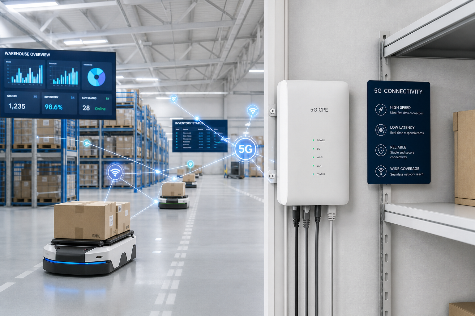
    Manufacturing giants in Germany, Japan, South Korea, and increasingly Southeast Asia are deploying private 5G to support automated guided vehicles (AGVs), real-time machine vision inspection systems, collaborative robotics, and digital twin synchronization — all of which place exacting demands on the CPE at the network edge.

    What Industrial 5G CPE Must Deliver

    The migration from carpeted-office CPE to industrial-grade devices requires a significant architectural rethink. Industrial 5G CPE must deliver:

    • Ruggedized Enclosures with IP65+ Ratings: Factory floors expose equipment to dust, moisture, vibration, and wide temperature ranges (-40°C to +70°C). Consumer-grade plastic housings simply will not survive. Industrial CPE designs now incorporate die-cast aluminum chassis, fanless thermal management, and DIN-rail mounting options for control cabinet integration.
    • Ultra-Reliable Low-Latency Communication (URLLC): Private 5G networks supporting closed-loop industrial control require CPE that can sustain sub-5ms latency with 99.999% reliability. This means optimized 5G NR modem firmware, hardware-accelerated packet processing, and IEEE 802.1 Time-Sensitive Networking (TSN) translation at the CPE-to-Ethernet boundary.
    • Multi-RAT Redundancy: Industrial operators increasingly require CPE that can failover between private 5G, public 5G, and Wi-Fi 7 without session interruption. This multi-radio architecture ensures production lines keep running even if the private 5G core experiences maintenance downtime.
    • Edge Compute Capacity: Forward-looking industrial CPE designs are embedding ARM-based application processors capable of running containerized edge workloads — predictive maintenance models, local video analytics, and protocol translation — directly on the CPE, reducing backhaul traffic and cloud dependency.

    Regional Deployment Patterns

    Southeast Asian manufacturers, including electronics assembly plants in Vietnam and automotive parts suppliers in Thailand, are emerging as aggressive private 5G adopters. These greenfield deployments often leapfrog wired industrial Ethernet entirely, using private 5G CPE as the primary WAN gateway for entire production cells. In contrast, European manufacturers tend to deploy private 5G as an overlay alongside existing PROFINET and EtherCAT infrastructure, demanding CPE with sophisticated Layer 2/3 bridging and industrial protocol awareness.

    The procurement pattern is also shifting: whereas early private 5G trials were led by mobile network operators offering managed services, 2026 is seeing a rise in direct enterprise procurement of CPE through system integrators and OEM channels. This creates new opportunities for CPE vendors who can offer flexible, standards-compliant devices that integrate easily with multiple private core vendors — Nokia NDAC, Ericsson Private 5G, Microsoft Azure Private MEC, and emerging Open RAN-based cores.

    Spectrum Liberalization Unlocks New Markets

    Regulatory developments are accelerating adoption. Germany’s BNetzA has expanded its 3.7-3.8 GHz local licensing program, Japan’s MIC now permits enterprises to operate private 5G in the 4.6-4.9 GHz band, and several ASEAN nations are finalizing private network spectrum frameworks modeled on the UK’s Ofcom shared-access approach. Each spectrum band and regulatory regime imposes specific CPE requirements around band support, power limits, and interference coordination — creating a complex matrix that CPE vendors must navigate.

    The CPE Opportunity for B2B Vendors

    For B2B telecom equipment providers, the industrial private 5G CPE segment represents a high-margin, high-growth opportunity distinct from the price-sensitive consumer FWA market. Enterprises are willing to pay a premium for CPE that comes with industrial certifications (IEC 61850-3, EN 50155 for rail applications), comprehensive remote management APIs, and multi-year lifecycle support commitments.

    As private 5G moves from the innovation lab to the production floor, CPE is no longer a simple modem-and-router box — it is becoming the intelligent edge node that bridges operational technology (OT) and information technology (IT) in the Industry 4.0 era. CPE vendors who invest now in ruggedized industrial designs, TSN integration, and edge computing capabilities will be well-positioned to capture this rapidly expanding market segment through 2027 and beyond.

  • A Technical Buyer’s Guide to QoS and Network Slicing in 5G CPE: End-to-End Slice-Aware Architecture, 5QI Mapping, and Multi-Service Deployment Planning for Operators

    A Technical Buyer’s Guide to QoS and Network Slicing in 5G CPE: End-to-End Slice-Aware Architecture, 5QI Mapping, and Multi-Service Deployment Planning for Operators

    Network slicing is one of the defining architectural features of 5G Standalone (SA), enabling operators to deliver multiple virtualized networks over a shared physical infrastructure — each with its own performance characteristics, security policies, and service guarantees. For CPE buyers, understanding how network slicing is implemented at the subscriber endpoint is essential to making informed procurement decisions. This guide examines the QoS framework, slice identification, and CPE-level architecture that operators need to evaluate when selecting 5G CPE for multi-service deployments.

    The 5G QoS Model: Beyond 4G Bearer Architecture

    5G introduces a fundamentally more flexible QoS framework than 4G LTE. The 5G QoS Identifier (5QI) replaces the QCI model with finer granularity and standardized packet delay budgets across 33 defined 5QI values (versus 9 QCIs in LTE). Key 5QI characteristics that CPE must handle include:

    • GBR (Guaranteed Bit Rate) QoS Flows for services requiring committed throughput, such as enterprise VPN tunnels, real-time video conferencing, and industrial control traffic
    • Non-GBR QoS Flows with standardized priority levels, suitable for general internet access and best-effort enterprise traffic
    • Delay-Critical GBR (5QI 82-85) for ultra-reliable low-latency applications requiring sub-5ms packet delay budgets
    • Reflective QoS — where the CPE derives uplink QoS rules from downlink packet markings, reducing signaling overhead for dynamic traffic patterns

    A properly designed 5G CPE must maintain independent QoS flow state for multiple concurrent PDU sessions, each potentially carrying multiple QoS flows with different 5QI profiles. This is a non-trivial requirement that separates enterprise-grade CPE from consumer-grade devices.

    Network Slice Identification: NSSAI and S-NSSAI

    Network slicing in 5G is identified through the Single Network Slice Selection Assistance Information (S-NSSAI), composed of a Slice/Service Type (SST) and an optional Slice Differentiator (SD). Standardized SST values include eMBB (SST=1), URLLC (SST=2), and MIoT (SST=3), with operator-defined values available for custom slice types.

    The CPE receives a Configured NSSAI from the core network during registration, which defines the slices the device is authorized to access. Critically, the CPE must then be capable of establishing separate PDU sessions on different slices simultaneously — a capability known as multi-slice support. For enterprise CPE deployments, this means one device might concurrently maintain:

    • A URLLC slice PDU session for factory automation traffic (SST=2, latency <5ms)
    • An eMBB slice PDU session for office internet access (SST=1, high throughput)
    • A custom MIoT slice for sensor aggregation (SST=3, low power, massive connectivity)

    URSP: The Traffic-to-Slice Routing Engine

    The UE Route Selection Policy (URSP) is the mechanism by which the 5G core instructs the CPE on how to route application traffic to specific network slices. URSP rules consist of traffic descriptors (IP tuples, FQDN, DNN, application IDs) mapped to route selection descriptors (S-NSSAI, DNN, SSC mode).

    For enterprise buyers, URSP support in CPE translates to a practical capability: the ability to enforce slice-based traffic steering without per-application configuration on end-user devices behind the CPE. A well-implemented CPE can, for example, automatically route all traffic destined for a manufacturing execution system to the URLLC slice while directing office productivity traffic to the eMBB slice — transparently to the LAN devices.

    Multi-Slice CPE Architecture: VLAN-to-Slice Mapping

    Enterprise-grade 5G CPE typically implements slice-to-VLAN mapping as the bridge between the 5G WAN and the local area network. Each PDU session (one per slice) is mapped to a distinct VLAN on the CPE’s LAN ports, allowing downstream switches and routers to segregate traffic by slice without 5G awareness.

    A reference multi-slice CPE architecture includes:

    • Multi-PDU Session Engine — supporting 4-8 concurrent PDU sessions with independent IP stacks per session
    • URSP Client — processing URSP rules from the 5G core and maintaining a local traffic-to-slice routing table
    • VLAN Translation Layer — mapping each PDU session to a configurable 802.1Q VLAN tag on the LAN side
    • Per-Slice QoS Enforcement — maintaining independent QoS flow state per PDU session with hardware-accelerated packet scheduling

    Performance and Isolation Guarantees

    A critical procurement consideration is the degree of resource isolation between slices at the CPE level. While the 5G core guarantees slice isolation within the network, the CPE itself must not become a bottleneck through shared buffer contention, CPU oversubscription, or inadequate packet scheduling. Buyers should verify:

    • Per-slice throughput floors that are maintained regardless of traffic load on other slices
    • Hardware queue separation — dedicated hardware queues per slice rather than software-based prioritization
    • Slice-specific latency budgets measured end-to-end from LAN ingress to 5G air interface
    • Fail-open behavior — documented behavior when a slice becomes unavailable (traffic fallback policies)

    Buyer’s Verification Checklist

    When evaluating 5G CPE for multi-slice deployment, procurement teams should request:

    1. Documented multi-PDU session support with a minimum of 4 concurrent sessions
    2. URSP rule capacity (minimum 8 traffic descriptor + route selection descriptor pairs)
    3. VLAN-to-slice mapping configuration interface (GUI and TR-069/TR-369 manageable)
    4. Per-slice throughput and latency test reports under simultaneous multi-slice load
    5. Interoperability test results with the operator’s specific 5G SA core vendor (Ericsson, Nokia, Huawei, Samsung, Mavenir)
    6. Software upgrade path for 3GPP Release 17/18 slice enhancements including slice-level authentication and authorization (NSSAA)

    Conclusion: Slice-Aware CPE as a Competitive Requirement

    As 5G SA networks mature through 2026, network slicing is transitioning from a standards capability to a commercial service differentiator. Operators launching enterprise slicing services need CPE that translates core-network slice intelligence into practical LAN-side traffic management. CPE without robust multi-slice support, URSP processing, and per-slice QoS enforcement will increasingly limit an operator’s ability to monetize their 5G SA investment. For procurement teams, slice-aware CPE is not a future consideration — it is a present requirement for any 5G SA deployment targeting enterprise, industrial, or multi-service consumer markets.

  • Open RAN and Virtualized RAN Architectures Gain Procurement Momentum: How O-RAN Interoperability Is Reshaping CPE Requirements for Global Operators in H2 2026

    Open RAN and Virtualized RAN Architectures Gain Procurement Momentum: How O-RAN Interoperability Is Reshaping CPE Requirements for Global Operators in H2 2026

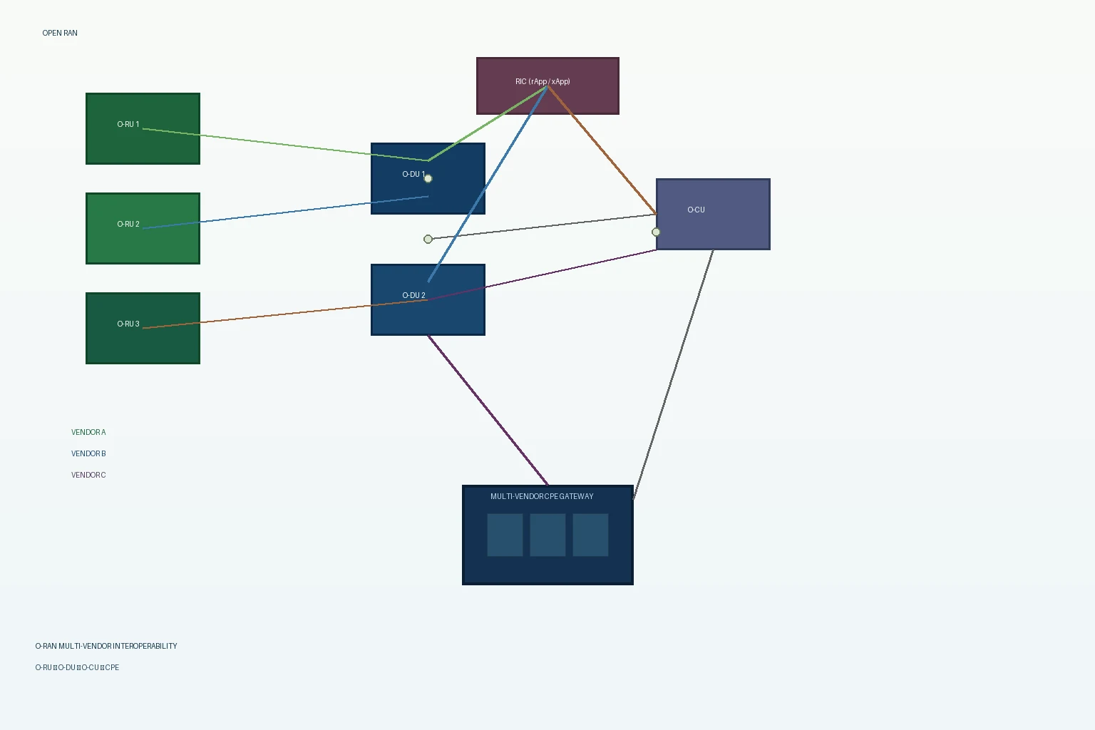
    The Open RAN (O-RAN) movement has entered a decisive procurement phase in 2026. What was once an industry aspiration has now become a formal requirement in operator RFPs across multiple regions, and the implications for CPE vendors and buyers are significant. As virtualized RAN (vRAN) deployments scale from pilot projects to commercial networks, the CPE ecosystem must adapt to a more open, interoperable, and software-driven radio access environment.

    The O-RAN Procurement Shift in 2026

    Several major operators — including Vodafone, Deutsche Telekom, Rakuten Mobile, and Reliance Jio — have now committed over 40% of their RAN spend to O-RAN-compliant infrastructure. The O-RAN Alliance’s specifications, particularly the O1, O2, and Open Fronthaul interfaces, are being adopted as procurement checklists by regulators in the EU, Japan, and Southeast Asia. For CPE manufacturers, this means that interoperability with O-RAN architectures is rapidly becoming a baseline requirement rather than a competitive differentiator.

    The GSMA’s June 2026 Open Gateway update further underscores this trend, extending API-driven network openness from the core to the RAN edge — and by extension, to the CPE that terminates the subscriber link.

    How O-RAN Reshapes CPE Technical Requirements

    Traditional RAN-CPE coupling has long tied subscriber devices to specific vendor ecosystems through proprietary scheduling algorithms, custom beamforming implementations, and closed-loop power control. O-RAN disaggregation breaks this coupling in three critical ways:

    1. Open Fronthaul Interface. The O-RAN 7.2x split between O-DU and O-RU means that physical-layer processing is separated from higher-layer scheduling. CPE must now demonstrate consistent performance across mixed-vendor RU/DU combinations rather than optimizing for a single vendor’s proprietary stack. For operators running multi-vendor O-RAN deployments, CPE that shows vendor-agnostic throughput and latency characteristics has a measurable procurement advantage.

    2. RIC (RAN Intelligent Controller) Integration. The near-real-time RIC introduces AI/ML-driven policy updates to the RAN scheduler. CPE with open telemetry capabilities — specifically the ability to report per-flow QoS metrics, radio conditions, and mobility events via standards-based APIs — enables RIC applications to optimize resource allocation dynamically. This creates a feedback loop where intelligent CPE improves RAN efficiency, which in turn improves CPE performance.

    3. Service Management and Orchestration (SMO). The O1 interface for network management extends logically to CPE management. O-RAN-aligned operators increasingly expect CPE to integrate with their SMO framework via standardized YANG models and NETCONF/RESTCONF protocols, enabling zero-touch provisioning and automated fault management across the entire RAN-to-CPE chain.

    Regional Adoption and CPE Certification Trends

    Japan leads global O-RAN adoption, with NTT DOCOMO and KDDI now requiring O-RAN Alliance certification for CPE supplied to their 5G SA networks. The European Commission’s Digital Decade 2030 policy framework mandates O-RAN interoperability testing for public-funded broadband projects starting in Q3 2026, directly affecting CPE procurement for rural FWA deployments.

    In North America, the NTIA’s Public Wireless Supply Chain Innovation Fund has allocated USD 420 million for O-RAN testing facilities, including CPE interoperability labs. Dish Wireless (EchoStar) continues to operate the world’s largest commercial O-RAN network, and its CPE certification program has become a de facto benchmark for O-RAN-compatible subscriber equipment.

    Southeast Asian markets — particularly Malaysia, Indonesia, and Vietnam — are leapfrogging directly to O-RAN architectures for new 5G builds, creating substantial demand for O-RAN-compatible CPE across multiple price tiers.

    CPE Buyer’s Checklist: O-RAN Readiness

    Operators and distributors evaluating CPE for O-RAN environments should verify:

    • Multi-vendor interoperability test reports — documented performance across at least two independent O-DU/O-RU combinations using O-RAN 7.2x fronthaul
    • RIC compatibility — support for E2 interface KPIs including per-flow throughput, BLER, RSRP/RSRQ reporting in O-RAN-defined formats
    • SMO integration readiness — TR-069/TR-369 (USP) support with YANG data models aligned to O-RAN O1 interface specifications
    • Open Fronthaul validation — O-RAN Alliance Open Testing and Integration Centre (OTIC) certification or equivalent third-party validation
    • Software upgradeability — capability to receive OTA firmware updates that align with RIC policy changes without service interruption

    Strategic Implications for H2 2026 and Beyond

    The O-RAN procurement momentum is not a future trend — it is a current reality accelerating through H2 2026. CPE that is tested, certified, and proven in O-RAN environments will capture procurement preference in markets representing over 60% of global 5G capex. For operators, the transition to O-RAN-compatible CPE procurement is both a technical necessity and a strategic lever for vendor diversification, cost reduction, and network programmability.

    For CPE manufacturers, the message is clear: O-RAN interoperability is no longer optional. It is the foundation upon which the next generation of operator CPE procurement will be built.

  • A Technical Buyer’s Guide to eSIM and Multi-IMSI Architecture in 5G CPE: eUICC Integration, GSMA Compliance, and Remote SIM Provisioning for Global Operator Deployments

    A Technical Buyer’s Guide to eSIM and Multi-IMSI Architecture in 5G CPE: eUICC Integration, GSMA Compliance, and Remote SIM Provisioning for Global Operator Deployments

    As 5G fixed wireless access deployments scale globally, a seemingly simple component — the SIM — is undergoing a transformation that has far-reaching implications for CPE procurement, logistics, and operational efficiency. The embedded SIM (eSIM) and its multi-IMSI architecture, governed by GSMA’s SGP.22 and SGP.32 specifications, enable operators to provision, swap, and manage operator profiles on CPE devices without physical SIM card handling. For ISPs, MVNOs, and enterprise operators managing fleets of thousands of distributed CPE units, eSIM technology is not a convenience feature — it is a strategic procurement requirement that directly impacts total cost of ownership, supply chain agility, and subscriber churn.

    This technical buyer’s guide examines the eSIM and multi-IMSI architecture as it applies to 5G CPE, covering the GSMA compliance framework, hardware integration considerations, remote SIM provisioning workflows, and practical vendor evaluation criteria for procurement teams specifying next-generation FWA devices.

    eSIM Architecture Fundamentals: eUICC, Profiles, and the LPA

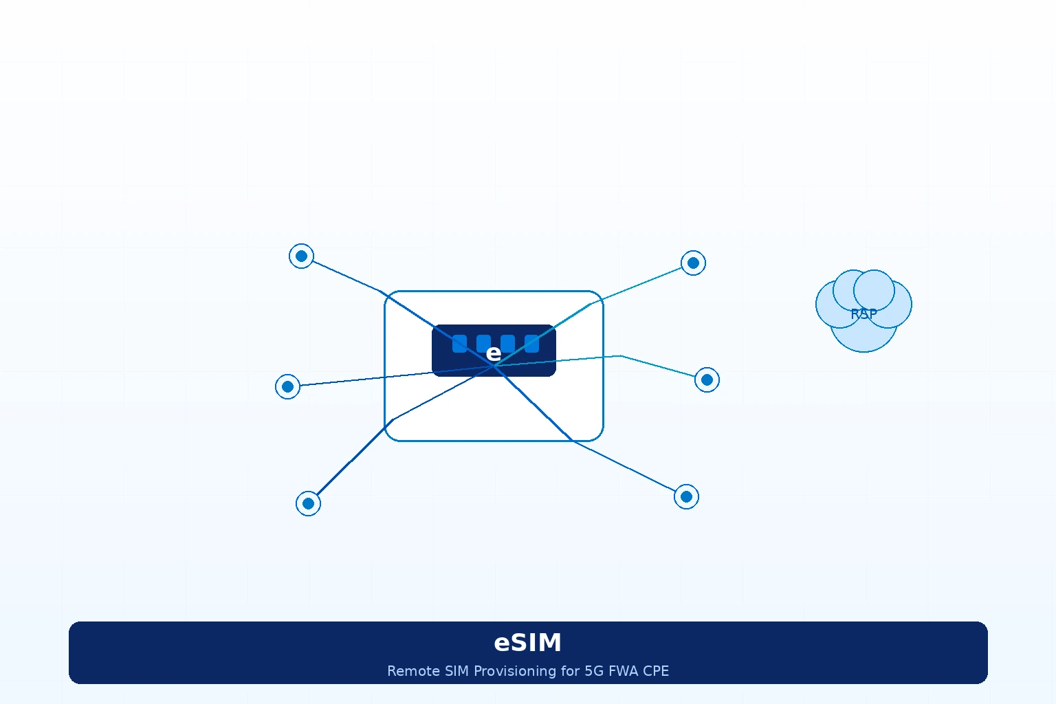
    At the hardware level, an eSIM implementation in a 5G CPE device consists of an embedded UICC (eUICC) — a soldered, tamper-resistant secure element that conforms to the GSMA SGP.02 (M2M) or SGP.22 (consumer) architecture. Unlike a traditional removable SIM card, the eUICC supports multiple operator profiles stored simultaneously, with secure over-the-air (OTA) profile download, activation, and deletion managed through a Local Profile Assistant (LPA) component integrated into the CPE’s baseband or application processor.

    The key architectural choice for CPE procurement teams is between the M2M eUICC architecture (GSMA SGP.02) and the consumer eUICC architecture (GSMA SGP.22):

    M2M eUICC (SGP.02). Designed for device-to-device and IoT use cases, the M2M architecture uses a “push” model where the operator’s Subscription Manager-Data Preparation (SM-DP) server pushes profiles to the eUICC through a Subscription Manager-Secure Routing (SM-SR) intermediary. This architecture is well-suited to fixed-location CPE with predictable network attachment patterns, but it requires operator-side SM-SR infrastructure that not all MVNOs maintain.

    Consumer eUICC (SGP.22). The consumer architecture uses a “pull” model where the CPE’s LPA initiates profile download from the SM-DP+ server — the operator-controlled platform that prepares and delivers encrypted profiles. SGP.22 is the dominant architecture for smartphones and is increasingly adopted in FWA CPE because it enables end-user or installer-initiated profile switching, supports QR-code-based activation workflows, and integrates naturally with operator mobile apps and self-service portals.

    For most FWA and enterprise CPE deployments, SGP.22 consumer eUICC is the recommended architecture due to broader ecosystem support, simpler operator onboarding, and alignment with GSMA SGP.32 — the emerging IoT eSIM standard that extends consumer architecture capabilities to constrained devices.

    Multi-IMSI Architecture: Enabling Operator Flexibility at the CPE Level

    While eSIM enables profile portability, multi-IMSI capability enables profile concurrency. A multi-IMSI CPE device stores multiple International Mobile Subscriber Identities — each associated with a distinct operator profile — and can switch between them based on network availability, cost optimization rules, or geographic location without requiring a profile download.

    In a 5G CPE context, multi-IMSI architecture serves three primary deployment scenarios:

    Multi-Carrier Failover for SLA-Grade Deployments. Enterprise CPE deployed at branch offices, retail locations, or remote industrial sites can maintain active IMSIs from two or more operators. If the primary operator’s network experiences congestion or an outage, the CPE’s connection manager — typically implemented in the modem firmware or an SDK-provided middleware layer — triggers an IMSI switch to the secondary operator within seconds, maintaining session continuity for critical applications.

    Cross-Border Roaming Optimization. For logistics, transportation, and maritime CPE deployments that cross national boundaries, multi-IMSI with pre-loaded regional operator profiles eliminates roaming charges by enabling the CPE to attach as a local subscriber in each country. The eUICC’s profile management logic, combined with a steering-of-roaming application, selects the lowest-cost profile for the current geographic region — a capability that can reduce connectivity costs by 40–70% compared to international roaming.

    MVNO and Wholesale Operator Multi-Tenancy. MVNOs that resell connectivity from multiple host operators can deploy a single CPE SKU with pre-provisioned MNO profiles, activating the appropriate IMSI at subscriber onboarding based on the subscriber’s service plan and coverage area. This eliminates the logistical complexity of stocking operator-specific CPE variants and enables dynamic MNO switching if the MVNO renegotiates wholesale agreements.

    Remote SIM Provisioning Workflow: From Factory to Field Deployment

    The GSMA-defined RSP (Remote SIM Provisioning) workflow for consumer eUICC CPE follows a four-phase lifecycle:

    Phase 1: Factory Provisioning. During CPE manufacturing, the eUICC is loaded with a provisioning profile — a bootstrap connectivity profile that enables the device to attach to a cellular network for the sole purpose of downloading its operational profile. The eUICC’s EID (eUICC ID) is registered with the SM-DP+ server that will manage the device’s profile lifecycle.

    Phase 2: Subscriber Onboarding. When a subscriber activates the CPE, the operator provides an activation code — typically delivered as a QR code, a deep link in an operator app, or an SM-DP+ address string in the device’s zero-touch provisioning payload. The CPE’s LPA uses this activation code to establish a secure TLS session with the SM-DP+ server, authenticate via the eUICC’s certificate chain, and download the encrypted operational profile.

    Phase 3: Operational Profile Activation. The downloaded profile is installed into an available profile slot on the eUICC, the CPE detaches from the provisioning network, and re-attaches using the operational IMSI. From this point forward, the CPE operates as a standard subscriber device on the selected MNO network.

    Phase 4: Lifecycle Management. The operator can remotely enable, disable, or delete profiles through SM-DP+ commands. Profile switching between multiple downloaded profiles (e.g., primary to backup MNO) is managed locally by the LPA based on policy rules configured by the operator or enterprise administrator. The GSMA SGP.32 specification, currently in advanced draft, extends this lifecycle model with bulk profile management capabilities tailored to IoT and CPE fleets.

    Hardware Integration Considerations for CPE OEMs and ODMs

    For procurement teams evaluating CPE with eSIM capability, the following hardware integration factors should be verified against deployment requirements:

    eUICC Chip Selection. The two dominant eUICC secure element vendors — Thales (formerly Gemalto) and G+D (Giesecke+Devrient) — supply GSMA SAS-certified eUICCs with support for both SGP.02 and SGP.22 architectures. STMicroelectronics and Infineon also offer eUICC silicon for cost-optimized IoT and CPE applications. Buyers should verify that the selected eUICC supports the number of concurrent profiles required for the deployment scenario — typically 2–5 profiles for multi-IMSI CPE — and that profile switching latency (measured from IMSI detach to re-attach) meets the service-level requirements for failover applications.

    LPA Integration Model. The LPA can be implemented in the modem baseband processor (modem-resident LPA), in the CPE’s application processor (AP-resident LPA), or as a hybrid implementation. Modem-resident LPAs (e.g., Qualcomm’s eSIM framework on Snapdragon X-series modems, MediaTek’s eSIM stack on T-series modems) offer tighter integration with radio state management and lower profile-switching latency. AP-resident LPAs offer greater flexibility for custom operator management UIs and integration with TR-069/TR-369 ACS platforms for remote profile lifecycle management.

    Antenna and RF Path Considerations. The provisioning profile bootstrapping phase requires the CPE to achieve network attachment using only the eUICC’s default provisioning IMSI — typically associated with a partner MNO or a global connectivity provider. CPE procurement teams should confirm that the device’s antenna configuration and supported bands cover the provisioning partner’s spectrum in all target deployment geographies, and that the provisioning data path (typically limited to a few megabytes for profile download) does not exhaust a metered bootstrap data allowance.

    GSMA Compliance and Security Certification

    Any CPE claiming eSIM support should hold GSMA SAS (Security Accreditation Scheme) certification for both the eUICC silicon (SAS-UP) and the SM-DP+ platform (SAS-SM). Additionally, the CPE’s LPA implementation should comply with GSMA SGP.22 v2.4 or later, which includes mandatory support for TLS 1.2 profile delivery encryption and the profile interoperability testing framework defined in GSMA TS.48.

    Buyers should request SAS certification documentation from CPE vendors and verify that the eUICC vendor’s SM-DP+ integration has been validated against the operator’s profile delivery infrastructure. In multi-operator deployments, the CPE’s eUICC must support profile policy rules (PPR) as defined in SGP.22 section 3.1.3, enabling the primary operator to control which secondary profiles can coexist on the device.

    eSIM vs. iSIM: The Next Integration Step

    Looking beyond eSIM, the integrated SIM (iSIM) — where the UICC functionality is embedded directly into the modem’s system-on-chip (SoC) silicon, eliminating the discrete eUICC component — is beginning to appear in cost-optimized CPE designs. Qualcomm’s Snapdragon X80 modem-RF platform and Sony Semiconductor’s Altair ALT1350 chipset both support iSIM architectures compliant with GSMA SGP.31/32 specifications.

    iSIM reduces BOM cost (approximately $0.40–0.80 per unit versus discrete eUICC), decreases PCB footprint, and lowers power consumption — advantages that become significant in high-volume CPE deployments. However, the iSIM ecosystem is less mature than eSIM, and operator certification timelines for iSIM-based CPE can extend 3–6 months longer than equivalent eSIM designs. For procurement decisions in 2026, eSIM remains the recommended architecture for mainstream FWA CPE, with iSIM as a forward-looking option for cost-optimized SKUs targeting 2027-2028 volume deployments.

    Vendor Selection Criteria: What to Ask CPE Suppliers

    When evaluating 5G CPE with eSIM and multi-IMSI capability, procurement teams should include the following requirements in RFQ documentation:

    1. GSMA SAS certification status for the eUICC component and the SM-DP+ integration path.
    2. Supported number of concurrent eSIM profiles and measured profile switching latency (detach-to-attach time) under representative network conditions.
    3. LPA integration model (modem-resident, AP-resident, or hybrid) and compatibility with standard ACS platforms (TR-069/TR-369) for remote lifecycle management.
    4. Multi-IMSI failover behavior — including automatic vs. policy-driven IMSI switching, and support for steering-of-roaming applications — with documented performance under network degradation scenarios.
    5. Provisioning profile coverage in target deployment geographies, including bootstrap data allowance sufficient for operational profile download.
    6. SM-DP+ platform compatibility with the buyer’s existing or planned operator partners, including multi-tenant SM-DP+ support for MVNO and wholesale deployments.
    7. Firmware OTA (FOTA) update capability for the eSIM LPA stack, ensuring future GSMA specification updates can be deployed without field returns.

    For operators building large-scale FWA deployments — particularly those spanning multiple countries or serving enterprise SLA-grade subscribers — eSIM and multi-IMSI capability in CPE is not an optional feature. It is a foundational requirement that determines the speed of subscriber onboarding, the cost of ongoing profile management, and the ability to deliver carrier-grade reliability through multi-operator redundancy. By incorporating these technical evaluation criteria into the CPE procurement process, operators can future-proof their device fleet against profile management complexity and position their FWA services for sustainable growth through 2027 and beyond.

  • 5G-Advanced (3GPP Release 18) Commercial Rollouts Begin: How AI-Enhanced Network Capabilities and Extended IoT Support Are Opening New CPE Product Categories for Operators in H2 2026

    5G-Advanced (3GPP Release 18) Commercial Rollouts Begin: How AI-Enhanced Network Capabilities and Extended IoT Support Are Opening New CPE Product Categories for Operators in H2 2026

    The 5G-Advanced era is no longer a roadmap item — it is a commercial reality. In the first half of 2026, multiple Tier-1 operators across Asia, Europe, and North America have begun activating 3GPP Release 18 features on their live 5G Standalone (SA) networks, marking the industry’s formal transition from foundational 5G to the enhanced capabilities defined in the 5G-Advanced specification set. For CPE buyers — ISPs, MVNOs, system integrators, and enterprise procurement teams — this transition opens a new generation of customer-premises equipment designed to exploit AI-native radio optimization, enhanced uplink performance, and expanded IoT protocol support that were simply unavailable in Release 17 devices.

    What 5G-Advanced Brings to the CPE Layer

    Release 18 introduces several architectural enhancements that directly affect CPE design and procurement specifications. The most consequential for fixed wireless access (FWA) and enterprise CPE include:

    AI/ML Framework for NR Air Interface. For the first time, 3GPP has standardized AI/ML-based channel state information (CSI) feedback compression, beam management, and positioning accuracy enhancements. CPE chipsets that support Release 18 can leverage network-side AI models to improve beam selection in dense urban environments, reduce CSI reporting overhead, and achieve more consistent throughput at cell edges. For operators, this translates to higher average sector spectral efficiency and fewer subscriber complaints about evening-hour performance degradation.

    Enhanced Multi-TRP (mTRP) and Carrier Aggregation. Release 18 extends multi-transmission-reception-point coordination beyond Release 17, enabling CPE devices to simultaneously receive data from multiple gNB panels with tighter inter-panel synchronization. Combined with expanded carrier aggregation (CA) configurations — including inter-band CA across sub-6 GHz and mmWave spectrum — 5G-Advanced CPE can sustain multi-gigabit throughput with improved reliability for enterprise branch-office deployments where SLA-grade availability is non-negotiable.

    Expanded IoT Support: NR-Light Enhancements and Ambient IoT. Release 18 builds on the RedCap foundation laid in Release 17 with further reduced-capability enhancements and introduces the ambient IoT (Ambient IoT) framework — enabling ultra-low-power, battery-free tag devices that can backscatter ambient RF signals. While ambient IoT is primarily an infrastructure play, CPE gateways positioned as edge aggregation hubs will increasingly need to support ambient IoT device management and data relay, opening a new CPE product category for industrial and logistics verticals.

    XR-Aware Scheduling and Uplink Enhancements. For enterprise and prosumer use cases involving augmented reality, remote assistance, and real-time video analytics, Release 18’s XR-aware scheduling coordinates downlink and uplink traffic flows to meet the joint latency-throughput requirements of immersive applications. Uplink MIMO enhancements — including support for up to 4-layer UL transmission — give 5G-Advanced CPE the symmetric bandwidth profile that applications like multi-camera live streaming and cloud-rendered XR demand.

    Operator Rollout Timeline and CPE Availability

    China Mobile activated Release 18 features across its 5G SA network in Q1 2026, initially targeting enhanced MIMO and AI-based CSI optimization in high-density urban corridors. SK Telecom and KT followed with commercial 5G-Advanced service launches in Seoul and Busan during Q2 2026, with both operators explicitly positioning Release 18-capable CPE as a premium FWA tier for business subscribers. In Europe, Deutsche Telekom and Orange have announced plans to activate Release 18 features in select markets by Q3 2026, while in North America, T-Mobile US has begun lab trials with Release 18 CPE prototypes from Qualcomm’s Snapdragon X80 platform.

    On the silicon side, MediaTek’s T900 modem-RF platform and Qualcomm’s Snapdragon X80 modem-RF system are the first commercially available chipsets with full Release 18 feature support, and both vendors have reference designs for indoor and outdoor CPE form factors available to OEMs and ODMs. Honlly Telecom’s engineering team is currently evaluating both platforms for integration into the company’s 2027 CPE roadmap, with particular focus on the enhanced beam management and uplink MIMO capabilities that differentiate Release 18 from Release 17 devices in real-world deployments.

    Procurement Implications for Operators and ISPs

    For B2B buyers planning CPE procurement in H2 2026 and 2027, the 5G-Advanced transition introduces several strategic considerations:

    Timing the Release 17-to-18 Crossover. Operators with active Release 18 network deployments should begin specifying Release 18-capable CPE in RFQs immediately, as the AI-enhanced beam management alone can deliver 15–25% throughput improvement at mid-cell and cell-edge positions compared to equivalent Release 17 hardware. However, operators whose network infrastructure remains on Release 17 or NSA architecture may achieve better near-term ROI by continuing Release 17 CPE procurement through mid-2027 while planning the 5G-Advanced migration.

    IoT Gateway Convergence. The expanded IoT protocol support in Release 18 — including ambient IoT awareness and enhanced RedCap — positions the 5G-Advanced CPE as a converged FWA-plus-IoT gateway. Procurement teams evaluating CPE for industrial, logistics, and smart-city deployments should prioritize platforms that expose IoT management APIs alongside standard FWA functionality, reducing the need for separate IoT gateway hardware.

    Power and Thermal Envelope. The additional AI processing, enhanced MIMO layers, and wider carrier aggregation configurations in 5G-Advanced CPE increase both peak power consumption and thermal dissipation requirements. Buyers should verify that Release 18 CPE designs include adequate thermal engineering — particularly for outdoor and industrial-grade units — and that power budgets align with deployment-site constraints.

    Looking Ahead: Release 19 and the 6G Pathway

    While the industry digests Release 18, 3GPP is already advancing Release 19 specifications — targeted for freeze in late 2025 — with further AI/ML integration, integrated sensing and communication (ISAC), and foundational 6G study items. For CPE procurement teams, the Release 18 commercial activation in 2026 represents the beginning of a multi-year technology refresh cycle that will progressively bring AI-native radio, ambient IoT, and sensing capabilities into the FWA and enterprise CPE product categories. The operators and ODMs that move early to build 5G-Advanced CPE supply chains will be best positioned to capture the premium tier of FWA subscribers as the technology matures through 2027 and beyond.

  • 5G Non-Terrestrial Network (NTN) Services Enter Commercial Phase: How Satellite-Direct-to-CPE Connectivity Is Opening New Rural and Maritime Markets for Telecom Operators in 2026

    5G Non-Terrestrial Network (NTN) Services Enter Commercial Phase: How Satellite-Direct-to-CPE Connectivity Is Opening New Rural and Maritime Markets for Telecom Operators in 2026

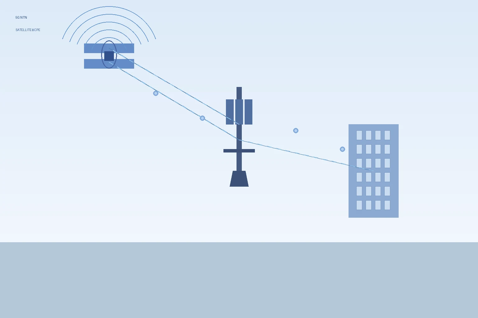
    The telecom industry is witnessing a paradigm shift in 2026 as 5G Non-Terrestrial Network (NTN) services move from standards documents to commercial reality. With 3GPP Release 17 NTN specifications finalized and Release 18 enhancements underway, satellite-direct-to-CPE connectivity is creating tangible new markets for telecom operators, ISPs, and MVNOs — particularly in rural, remote, maritime, and emergency-response segments where terrestrial infrastructure is economically unfeasible.

    What 5G NTN Means for CPE Procurement

    5G NTN enables direct communication between standard-compatible user equipment (UE) and low-earth orbit (LEO) satellite constellations. Unlike traditional satellite broadband that requires proprietary terminals and bulky dishes, NTN-compatible CPE leverages standardized 5G NR waveforms — meaning operators can deploy satellite-backhauled customer premises equipment using the same chipset ecosystems and supply chains they already rely on for terrestrial 5G.

    For telecom procurement teams, this convergence has three immediate implications:

    • Unified device roadmap: A single NTN-capable CPE platform can serve both terrestrial and satellite coverage areas, simplifying inventory management and reducing SKU complexity.
    • Addressable market expansion: Operators can extend service footprints into unserved and underserved areas — rural broadband, maritime vessels, remote mining and energy sites, and disaster recovery scenarios — without deploying additional terrestrial RAN infrastructure.
    • New service tier opportunities: NTN connectivity enables premium hybrid plans (terrestrial + satellite failover), guaranteed-uptime enterprise SLAs, and IoT backhaul for remote sensor networks.

    Commercial Deployments Accelerating in 2026

    Several landmark deployments have validated the NTN commercial model. T-Mobile’s partnership with SpaceX’s Starlink has progressed from emergency SMS beta testing in 2025 to commercial direct-to-cell data services covering over 500,000 square miles of previously unserved US territory. AST SpaceMobile has demonstrated 14 Mbps downlink to unmodified smartphones via its BlueWalker 3 test satellite, with its first five commercial BlueBird satellites now in orbit. Meanwhile, Lynk Global has secured roaming agreements with over 40 mobile network operators across 40+ countries for its satellite-direct-to-phone service.

    On the CPE side, MediaTek’s MT6825 NTN chipset — compliant with 3GPP Release 17 IoT-NTN — has been integrated into multiple commercial devices, demonstrating that the silicon ecosystem is maturing rapidly. Qualcomm’s Snapdragon X80 5G Modem-RF system, announced in early 2026, includes native NB-NTN support, further signaling that NTN capability will become a standard feature in premium CPE chipsets by late 2026.

    Technical Considerations for NTN-Capable CPE

    Buyers evaluating NTN-capable CPE should understand several critical technical factors:

    Frequency Band Support

    NTN operations in 2026 primarily utilize the n255 (L-band: 1626.5–1660.5 MHz uplink) and n256 (S-band: 1980–2010 MHz uplink) 3GPP-defined bands. CPE must support these bands alongside standard terrestrial 5G bands (n77, n78, n79 for Sub-6GHz; n257, n258, n260, n261 for mmWave). Dual-mode NTN+terrestrial CPE should support seamless handover between satellite and terrestrial RAN via the 3GPP-defined service continuity framework.

    Doppler Compensation and Timing Advance

    LEO satellites travel at approximately 7.8 km/s, creating significant Doppler shift (up to ±24 ppm in S-band) and rapidly varying propagation delay. NTN-capable CPE must implement GNSS-based pre-compensation for both frequency offset and timing advance, as specified in 3GPP TR 38.821. Buyers should verify that CPE vendors have implemented these compensation algorithms and validated performance with satellite operators.

    Antenna Design Requirements

    NTN CPE requires circularly polarized antenna designs with higher gain than typical terrestrial CPE. RHCP (Right-Hand Circular Polarization) is specified for satellite links. For outdoor CPE, integrated patch or helical antenna arrays with 5–7 dBi gain in L/S-band are typical. Indoor CPE presents greater challenges — window-mounted solutions with external antenna ports are likely to dominate early deployments.

    Market Outlook: 2026–2028

    Analyst projections indicate the satellite-direct-to-device market will reach $17–22 billion by 2028, driven by rural broadband mandates, maritime connectivity requirements, and IoT backhaul demand. The GSMA estimates that NTN could connect an additional 400 million people globally by 2030 who currently lack reliable terrestrial coverage.

    For telecom operators, the procurement window is opening now. Early-mover advantages include preferential satellite capacity agreements, customized CPE co-development with OEM partners, and first-to-market positioning in underserved regions. As the NTN ecosystem matures and chipset costs decline — from approximately $12–18 premium per NTN-capable modem in 2026 toward sub-$5 integration cost by 2028 — the business case for NTN-enabled CPE procurement strengthens considerably.

    Frequently Asked Questions

    What is 5G NTN and how does it differ from traditional satellite broadband?

    5G NTN (Non-Terrestrial Network) integrates satellite connectivity directly into the 3GPP 5G standard, enabling standard-compatible CPE to communicate with LEO satellites using the same 5G NR waveform. Unlike traditional satellite broadband (which requires proprietary modems and often uses GEO satellites with 600ms+ latency), NTN operates over LEO constellations at 25–50ms latency and uses standardized components — meaning CPE can seamlessly switch between terrestrial towers and satellites.

    Which spectrum bands are used for 5G NTN CPE?

    3GPP has defined specific NTN frequency bands: n255 (L-band: 1626.5–1660.5 MHz UL / 1525–1559 MHz DL) and n256 (S-band: 1980–2010 MHz UL / 2170–2200 MHz DL). These bands are globally harmonized for mobile satellite services (MSS). Future Release 18/19 enhancements may add support for Ka-band (17–30 GHz) for higher-throughput fixed CPE applications.

    When will NTN-capable CPE be commercially available at scale?

    NTN-capable CPE is already entering commercial production in 2026. MediaTek’s MT6825 IoT-NTN chipset is shipping in volume; Qualcomm’s X80 modem with NB-NTN support is sampling. Full NR-NTN (broadband) CPE supporting higher data rates is expected to reach commercial volume in late 2026 to early 2027, coinciding with the maturation of LEO constellations from SpaceX, AST SpaceMobile, and other providers.

    How should operators evaluate NTN CPE suppliers?

    Key evaluation criteria include: 3GPP Release 17/18 NTN compliance certification, field-validated Doppler compensation and GNSS-aided timing accuracy, support for both IoT-NTN (NB-IoT/eMTC) and NR-NTN (broadband) modes, circularly polarized antenna integration, seamless terrestrial-to-satellite handover capability, and flexible OTA firmware update architecture to accommodate evolving NTN standards and satellite constellation parameters.

    For more information about Honlly Telecom’s 4G/5G CPE solutions and OEM/ODM capabilities, contact our team.

  • A Technical Buyer’s Guide to 5G NR-U and CBRS Shared Spectrum CPE: Architecture, Spectrum Access Systems, and Enterprise Private Network Deployment Planning

    A Technical Buyer’s Guide to 5G NR-U and CBRS Shared Spectrum CPE: Architecture, Spectrum Access Systems, and Enterprise Private Network Deployment Planning

    As enterprise demand for private wireless networks accelerates, telecom operators and system integrators are increasingly looking beyond traditional licensed spectrum. Shared and unlicensed spectrum frameworks — specifically 5G NR-U (NR in Unlicensed spectrum) and CBRS (Citizens Broadband Radio Service) — offer a compelling middle ground: carrier-grade performance without the multi-million-dollar spectrum auction costs. For ISPs, MVNOs, and enterprise network architects evaluating CPE for private network deployments, understanding the architectural differences between NR-U, CBRS, and licensed spectrum is critical to making informed procurement decisions.

    Spectrum Frameworks Compared: Licensed, Shared, and Unlicensed

    Before evaluating specific CPE requirements, buyers should understand the three spectrum access models:

    Spectrum Type Access Model Key Bands Interference Management Best For
    Licensed Exclusive, auctioned n77, n78, n79, n257–n261 Operator-controlled MNO macro coverage, guaranteed SLA
    CBRS (Shared) 3-tier: Incumbent, PAL, GAA n48 (3550–3700 MHz) SAS coordinates spectrum access Enterprise private 5G, neutral host
    NR-U (Unlicensed) Shared, listen-before-talk n46 (5 GHz), n96 (6 GHz) LBT + channel access priority Indoor enterprise, industrial IoT

    5G NR-U Architecture: How It Works

    5G NR-U, standardized in 3GPP Release 16, extends 5G NR operation into unlicensed spectrum — primarily the 5 GHz (n46) and 6 GHz (n96) bands. Unlike Wi-Fi, which uses CSMA/CA contention, NR-U implements a more sophisticated channel access mechanism based on Listen-Before-Talk (LBT) with configurable channel access priority classes.

    NR-U supports two deployment modes:

    • Standalone NR-U (SNPN): The 5G network operates entirely in unlicensed spectrum without any licensed anchor. This mode is ideal for isolated enterprise deployments — factory floors, warehouse automation, campus networks — where the enterprise controls the physical RF environment and doesn’t need MNO integration.
    • License-Assisted Access (LAA/NR-U LAA): A licensed carrier serves as the primary cell (PCell) for control-plane signaling and mobility, while NR-U carriers provide additional data-plane capacity. This mode suits operators offering hybrid enterprise solutions that combine MNO-grade reliability with unlicensed capacity expansion.

    CBRS: The Three-Tier Spectrum Sharing Model

    The CBRS framework in the 3.5 GHz band (3550–3700 MHz, 3GPP band n48) operates under a three-tier access hierarchy managed by Spectrum Access Systems (SAS):

    1. Incumbent Access (Tier 1): U.S. Navy radar systems and fixed satellite service (FSS) earth stations receive absolute protection. SAS dynamically reallocates spectrum away from CBRS devices when incumbents are active in a given geographic area.
    2. Priority Access License (PAL, Tier 2): 10 MHz channels auctioned by county (U.S.). PAL holders receive interference protection from GAA users but must yield to incumbents. Up to 7 PAL licenses per county (70 MHz total).
    3. General Authorized Access (GAA, Tier 3): Open access to any FCC-certified CBRS device. GAA users operate opportunistically on whatever spectrum remains after incumbent and PAL allocations. No interference protection guaranteed.

    For CPE procurement, the critical takeaway is that CBRS CPE must include SAS client functionality — the device must register with an FCC-approved SAS provider (Google, Federated Wireless, Amdocs, Sony, Key Bridge, or Comsearch) and receive spectrum grants before transmitting. This adds a layer of complexity to device provisioning and fleet management.

    CPE Hardware Requirements for NR-U and CBRS

    Radio Front-End Considerations

    NR-U and CBRS CPE require radio front-end modules (FEMs) designed for the respective bands. For CBRS (n48), the 3550–3700 MHz range requires FEMs with adequate linearity and filtering to coexist with adjacent DoD radar systems. For NR-U in 5 GHz (n46), the CPE must coexist with Wi-Fi 6/6E/7 devices — requiring advanced filtering and dynamic channel selection to avoid adjacent-channel interference from existing Wi-Fi infrastructure.

    SAS Client Integration (CBRS-Specific)

    CBRS CPE must embed a SAS client (or CBSD — Citizens Broadband Radio Service Device) that:

    • Reports device geolocation (±50m horizontal, ±3m vertical accuracy) to SAS
    • Requests spectrum grants (frequency range + max EIRP) from SAS
    • Complies with SAS-initiated spectrum relinquishment commands within 60 seconds (for incumbent protection)
    • Supports CPI (Certified Professional Installer) registration for Category B CBSDs (higher-power outdoor deployments)

    Buyers should verify that CPE vendors have completed FCC Part 96 certification and interoperability testing with at least two major SAS providers.

    Channel Bandwidth and Carrier Aggregation

    CBRS supports carrier bandwidths up to 20 MHz per channel (up to 40 MHz with carrier aggregation of two PAL channels or 80 MHz with GAA aggregation). NR-U in 5 GHz supports 20/40/80 MHz channels. For enterprise applications requiring 200+ Mbps throughput, CPE should support at least 2×CA (component carrier aggregation) in CBRS mode or 80 MHz single-carrier in NR-U mode with 4×4 MIMO.

    Enterprise Deployment Scenarios

    Manufacturing and Industry 4.0

    NR-U standalone is well-suited for factory deployments where the enterprise owns the RF environment. A single NR-U CPE gateway on n46 (5 GHz) can serve as a local breakout point for AGV (Automated Guided Vehicle) control, machine vision data backhaul, and IIoT sensor aggregation — all without spectrum licensing costs or MNO dependency.

    Neutral Host and Multi-Operator Venues

    CBRS GAA is increasingly used for neutral host deployments in stadiums, airports, and enterprise campuses. CBRS-capable CPE can connect to multiple MNO core networks through a neutral host RAN, simplifying multi-operator indoor coverage. Buyers should look for CPE supporting Multi-Operator Core Network (MOCN) gateway functionality for neutral host use cases.

    Rural and Regional ISP Deployments

    For WISPs (Wireless ISPs) and regional operators, CBRS GAA offers a path to 5G-grade fixed wireless access without licensed spectrum. CBRS CPE deployed as FWA terminals can deliver 100–300 Mbps to rural subscribers using GAA spectrum, with the option to upgrade to PAL for guaranteed capacity in high-demand areas.

    Procurement Checklist for Shared Spectrum CPE

    When evaluating NR-U and CBRS CPE for enterprise or operator deployments, verify the following:

    • FCC Part 96 certification — mandatory for CBRS CPE sold in the U.S. market
    • SAS interoperability — tested with ≥2 SAS vendors (Google, Federated Wireless, etc.)
    • Band n48 support — full 3550–3700 MHz with 20/40/80 MHz channel bandwidths
    • Band n46 and/or n96 support — for NR-U operation in 5 GHz and 6 GHz
    • GNSS geolocation accuracy — ±50m horizontal / ±3m vertical for CBRS Category B
    • Listen-Before-Talk compliance — 3GPP TS 37.213 channel access procedures
    • 4×4 MIMO support — for sustained multi-gigabit throughput
    • Dual-mode NR-U + CBRS support — future-proofing for multi-spectrum deployments
    • TR-369 USP / TR-069 management — remote SAS grant management and spectrum analytics
    • OTA firmware upgrade capability — SAS protocol updates, regulatory compliance patches

    Market Outlook

    The shared and unlicensed spectrum CPE market is poised for significant growth. ABI Research projects that CBRS device shipments will exceed 15 million units annually by 2028, driven by enterprise private 5G adoption and WISP FWA deployments. The global NR-U CPE market is expected to reach $2.8 billion by 2028, fueled by industrial IoT and indoor enterprise use cases.

    For telecom buyers and system integrators, NR-U and CBRS represent a strategic opportunity to deliver private 5G solutions at a fraction of the cost of licensed spectrum — without compromising on performance, security, or reliability. Selecting the right CPE partner with comprehensive shared spectrum capabilities is the critical first step.

    Frequently Asked Questions

    What is the difference between NR-U and CBRS?

    NR-U operates in fully unlicensed spectrum (5 GHz and 6 GHz bands) using Listen-Before-Talk for coexistence with Wi-Fi and other technologies. CBRS operates in shared spectrum (3.5 GHz) under a three-tier access framework managed by Spectrum Access Systems (SAS), which provides coordinated interference protection. CBRS offers more predictable performance due to SAS coordination, while NR-U is fully opportunistic and requires coexistence with Wi-Fi.

    Do I need a spectrum license for CBRS CPE?

    For GAA (General Authorized Access) tier — no license required. CPE devices connect to SAS and receive dynamic spectrum grants at no cost. For PAL (Priority Access License) tier, which provides guaranteed interference protection for 10 MHz channels, a county-level auction license is required (U.S. only). Most enterprise deployments use GAA initially and add PAL if capacity guarantees become necessary.

    Can NR-U and CBRS CPE coexist in the same deployment?

    Yes. Dual-mode CPE supporting both n48 (CBRS) and n46/n96 (NR-U) is available and represents the most flexible procurement strategy. This allows enterprises to use CBRS GAA for primary coverage with SAS-coordinated reliability, while NR-U provides additional capacity expansion in 5 GHz or 6 GHz unlicensed spectrum. Some advanced CPE platforms also support LTE-LAA (License Assisted Access) alongside 5G NR-U for backward compatibility with existing LTE-based private networks.

    What throughput can I expect from shared spectrum CPE?

    With 80 MHz channel bandwidth, 4×4 MIMO, and 256 QAM, CBRS CPE can deliver approximately 600–900 Mbps downlink in GAA mode (CPE Category B, indoor). NR-U CPE in 6 GHz (n96) with 160 MHz channel can achieve 1.5–2.5 Gbps downlink under favorable RF conditions. These figures assume clean spectrum with minimal interference — actual throughput depends on SAS grant parameters (for CBRS), Wi-Fi coexistence (for NR-U), and deployment density.

    To discuss your private network CPE requirements and explore Honlly Telecom’s 4G/5G NR-U and CBRS-compatible solutions, contact our engineering team.

  • CPE Predictive Maintenance and AI-Driven Fault Detection: A Technical Buyers Guide to Embedded Analytics and Self-Healing Networks for ISPs and Operators

    CPE Predictive Maintenance and AI-Driven Fault Detection: A Technical Buyers Guide to Embedded Analytics and Self-Healing Networks for ISPs and Operators

    As fixed wireless access networks scale to millions of subscriber devices, the operational economics of truck rolls — sending a field technician to diagnose and replace faulty CPE — becomes one of the largest line items in an ISP’s operational expenditure budget. Industry data suggests that a single unnecessary truck roll costs between $150 and $350 in direct expenses, not including subscriber churn risk from prolonged service disruption. Predictive maintenance powered by embedded AI and machine learning is emerging as the most effective strategy for operators to slash these costs while improving subscriber satisfaction.

    The Economics of Reactive vs. Predictive CPE Maintenance

    Traditional CPE support follows a reactive model: the subscriber calls when service degrades, the help desk runs through scripted diagnostics, and if Layer 1 troubleshooting fails, a technician is dispatched — often carrying a replacement unit preemptively. By contrast, a predictive maintenance architecture enables the CPE itself to detect degradation patterns days or weeks before service impact occurs, allowing operators to resolve issues remotely or schedule proactive replacements during low-impact maintenance windows.

    The financial case is compelling. A mid-sized operator with 500,000 CPE units in the field can expect approximately 2-4% annual failure rates, translating to 10,000-20,000 truck rolls per year. Even a 40% reduction through predictive maintenance — a conservative target based on early commercial deployments — yields annual savings of $600,000 to $2.8 million, depending on per-roll costs. When factoring in reduced churn (subscribers experiencing multiple outages churn at 3-5x the baseline rate), the ROI typically exceeds 300% within 18 months.

    Embedded AI Architecture: What to Look for in CPE Hardware

    Not all CPE hardware is equally capable of supporting predictive maintenance workloads. Telecom buyers evaluating devices for AI-driven fleet analytics should prioritize the following hardware specifications:

    On-Device Processing Capability: The CPE SoC should include a dedicated NPU (Neural Processing Unit) or DSP capable of running lightweight inference models locally. Qualcomm’s Networking Pro series, MediaTek’s Filogic line, and Broadcom’s StrataXGS platforms all now include embedded ML accelerators suitable for CPE-class anomaly detection models. Look for at least 1 TOPS (Tera Operations Per Second) of ML inference performance.

    Telemetry Granularity: Effective predictive models require rich data inputs. The CPE should expose per-interface statistics (including RF parameters like RSRP, RSRQ, SINR, and CQI for cellular WAN links), CPU/memory utilization, temperature sensors at multiple board locations, flash wear metrics, and packet error rate trending at sub-minute intervals.

    Local Model Execution with OTA Updates: The architecture should support containerized ML model deployment via OTA firmware updates, allowing operators to deploy and iterate on detection models without replacing hardware. TR-369 USP (User Services Platform) provides standardized object models for ML model management, making it the preferred management protocol.

    Key Predictive Maintenance Use Cases

    1. RF Link Degradation Prediction

    Machine learning models trained on historical RSRP/RSRQ/SINR telemetry can detect the subtle signal degradation patterns that precede link failure — often 7-14 days in advance. Common root causes identified by these models include: antenna connector corrosion (detected through gradual RSRP decline correlated with humidity/temperature data), foliage growth obstructing fixed wireless links (seasonal SINR degradation patterns), and neighboring cell interference (CQI degradation without corresponding signal strength decline).

    2. Thermal Anomaly Detection

    CPE operating in unconditioned spaces — attics, outdoor enclosures, equipment closets — frequently experiences thermal stress that accelerates component aging. Embedded temperature sensors combined with ML-based anomaly detection can identify abnormal thermal signatures before they cause hardware failure. For example, a gradual increase in idle temperature of 3-5°C above the device’s baseline often signals dust accumulation blocking ventilation, while rapid temperature cycling may indicate failing thermal interface material between the SoC and heatsink.

    3. Flash Storage Wear Prediction

    CPE devices with frequent configuration writes, logging, or caching workloads experience NAND flash wear that eventually leads to read-only filesystem failure. ML models tracking write amplification, bad block count growth, and wear-leveling efficiency can predict flash failure within a 30-day window with >85% accuracy, enabling proactive replacement before the device bricks.

    4. Power Supply Health Monitoring

    Voltage rail monitoring combined with current draw trending can detect failing power adapters or onboard power regulation circuitry. ML models trained on normal operating envelopes can flag deviations as small as 2-3% from baseline — anomalies invisible to threshold-based alerting — enabling preemptive adapter replacement that prevents intermittent reboot loops and subscriber frustration.

    Cloud-Edge Architecture Considerations

    Predictive maintenance architectures typically employ a split-compute model: lightweight anomaly detection models run on the CPE itself (edge inference), while more computationally intensive training and fleet-wide pattern analysis execute in the operator’s cloud or NOC environment. Key architectural decisions include:

    Telemetry Data Volume Management: A fleet of 500,000 CPE units generating telemetry at 5-minute intervals produces approximately 144 million data points per day. Efficient data pipelines using time-series databases (InfluxDB, TimescaleDB) with downsampling and retention policies are essential. Consider Apache Kafka or NATS for telemetry ingestion at scale.

    Model Training Cadence: Initial models should be trained on at least 6-12 months of historical telemetry data correlated with known failure events. Ongoing retraining should occur weekly or bi-weekly as new failure signatures are captured. Federated learning approaches — where model updates are computed on subsets of CPE devices and aggregated centrally — can reduce cloud compute costs while preserving data privacy.

    Alert Prioritization and Integration: Predictive alerts must integrate with existing NOC workflows (ServiceNow, PagerDuty, Opsgenie) and should include confidence scores, predicted time-to-failure windows, and recommended remediation actions. Without this integration, prediction alerts risk being ignored as low-priority noise.

    Vendor Evaluation Checklist

    When evaluating CPE suppliers for predictive maintenance capabilities, telecom buyers should verify:

    • Does the CPE platform expose the required telemetry interfaces (TR-369 USP, NETCONF/YANG, or MQTT-based telemetry)?
    • Are ML models deployable via OTA firmware updates without factory intervention?
    • Does the SoC include sufficient on-device ML compute capacity (minimum 1 TOPS)?
    • Can the supplier provide reference ML model implementations or partner with analytics platform vendors?
    • Is telemetry data formatted using open standards (e.g., Protobuf, Avro) to avoid vendor lock-in?
    • Does the CPE firmware support configurable telemetry intervals and selective metric enablement to manage data volume?
    • What is the supplier’s roadmap for on-device AI capabilities in the next 12-24 months?

    The Bottom Line

    Predictive maintenance for CPE is not a futuristic concept — it is a commercially available capability that operators are deploying today. The combination of affordable on-device ML accelerators, mature time-series anomaly detection algorithms, and standardized telemetry protocols (particularly TR-369 USP) has created a readiness inflection point. For ISPs and operators managing fleets of 50,000 or more CPE units, the business case for embedded AI-driven predictive maintenance is clear: reduce truck rolls by 40-60%, cut subscriber churn by 20-30%, and transform field operations from reactive firefighting to proactive fleet health management.

  • 5G mmWave Indoor CPE Deployments Accelerate as Urban Operators Target High-Capacity Fixed Wireless for Multi-Dwelling Units in 2026

    5G mmWave Indoor CPE Deployments Accelerate as Urban Operators Target High-Capacity Fixed Wireless for Multi-Dwelling Units in 2026

    The global 5G mmWave indoor Customer Premises Equipment (CPE) market is entering a phase of accelerated commercial deployment, driven by urban operators seeking to relieve sub-6 GHz spectrum congestion and deliver multi-gigabit fixed wireless access (FWA) to high-density residential and enterprise environments. Industry analysts project that mmWave indoor CPE shipments will grow at a compound annual rate of 34% through 2028, with North America, Japan, South Korea, and select Southeast Asian markets leading adoption.

    Urban Capacity Crunch Drives mmWave Indoor CPE Adoption

    As metropolitan operators exhaust mid-band spectrum capacity, millimeter wave frequencies — particularly the 28 GHz and 39 GHz bands — are increasingly being leveraged for indoor FWA deployments. Unlike outdoor mmWave CPE that requires line-of-sight installation with professional mounting, next-generation indoor mmWave CPE units incorporate advanced beamforming antenna arrays capable of maintaining stable links through window glass and light building materials.

    “The technological breakthrough isn’t just in the modem — it’s in the antenna subsystem,” explains Hiroshi Tanaka, Principal Analyst at Tokyo-based Wireless Infrastructure Research. “We’re seeing phased-array designs with 64 to 128 antenna elements that can dynamically steer beams to find and lock onto reflected mmWave signals, making window-mounted indoor installation viable for the first time at commercial scale.”

    Key Drivers Behind the Surge

    Several converging factors are propelling mmWave indoor CPE deployments forward in mid-2026:

    Multi-Dwelling Unit (MDU) Broadband Competition: Property owners and managed service providers are deploying mmWave FWA as a fiber-alternative backbone for entire buildings, distributing bandwidth via existing Ethernet or Wi-Fi infrastructure to individual units. This architecture eliminates the per-unit installation cost of fiber while delivering symmetrical gigabit speeds.

    Enterprise Campus Connectivity: Corporations with distributed campus environments are adopting indoor mmWave CPE as a primary or redundant WAN link, particularly in locations where fiber buildout timelines extend beyond 12 months. The sub-5ms latency of mmWave links makes them suitable for real-time enterprise applications including UCaaS, cloud ERP, and video surveillance backhaul.

    Small Cell Densification Synergies: Urban 5G small cell rollouts — particularly in cities like Tokyo, Seoul, Singapore, and New York — are creating dense mmWave coverage footprints that indoor CPE can exploit. Operators are co-marketing small cell infrastructure with indoor CPE packages to enterprise and MDU customers.

    Silicon Cost Reduction: The availability of second-generation mmWave modem-RF chipsets from Qualcomm (X75/X80 series), MediaTek (T900), and Samsung (Exynos Modem 5500) has reduced the bill of materials for mmWave CPE by approximately 40% compared to 2024 reference designs, making sub-$300 retail price points achievable for volume operators.

    Technical Considerations for Operator Procurement

    Telecom procurement teams evaluating mmWave indoor CPE should consider the following technical specifications:

    • Antenna Module Design: Look for devices with at least 64-element phased arrays supporting 3D beamforming. Multi-panel designs that can simultaneously track multiple reflection paths provide superior link stability in non-line-of-sight indoor conditions.
    • Window Penetration Loss Compensation: Modern mmWave CPE should specify performance through common building materials — particularly low-E glass, which can attenuate mmWave signals by 25-35 dB. Units designed for window mounting should include automatic gain compensation algorithms.
    • Carrier Aggregation Support: Ensure the CPE supports 8CC or higher carrier aggregation across mmWave carriers, plus anchor band aggregation with sub-6 GHz for fallback reliability.
    • Thermal Management: Indoor mmWave CPE with integrated antenna arrays can generate 8-12W of thermal load. Passive cooling designs with adequate ventilation are essential for reliable 24/7 operation without fan noise.
    • 3GPP Release 17/18 Compliance: Verify support for NR-U (NR in Unlicensed Spectrum), enhanced IAB (Integrated Access and Backhaul), and the latest power-saving features.

    Regional Deployment Landscape

    North America: Verizon and T-Mobile are extending their mmWave FWA footprints into urban MDU markets, with Verizon reporting 28% penetration in its mmWave-covered MDU footprint. AT&T has launched an indoor mmWave CPE pilot program targeting enterprise branch offices in 12 metropolitan areas.

    Asia-Pacific: Japan’s Rakuten Mobile and KDDI have deployed over 180,000 indoor mmWave CPE units in the Tokyo-Osaka corridor. South Korea’s KT Corporation has integrated mmWave indoor CPE into its “GiGA Wire” MDU broadband product, targeting 500,000 units by end-2027.

    Southeast Asia: Singtel and AIS Thailand are evaluating mmWave indoor CPE for high-end residential and SME segments, driven by the rapidly increasing availability of 28 GHz spectrum in urban centers.

    Implications for the CPE Supply Chain

    The growing mmWave indoor CPE segment is reshaping procurement patterns. Where operators previously sourced separate outdoor mmWave and indoor sub-6 GHz CPE SKUs, an increasing number are consolidating around dual-mode indoor/outdoor mmWave + sub-6 GHz platforms. This trend favors CPE manufacturers with in-house antenna design capability and mmWave testing facilities — a competitive advantage for vertically integrated OEM/ODM partners.

    For telecom buyers, the key takeaway is clear: mmWave indoor CPE is no longer a niche technology. As urban spectrum congestion intensifies and silicon costs continue to decline, mmWave-capable indoor CPE is becoming an essential component of any competitive fixed wireless access portfolio targeting high-density metropolitan markets.