
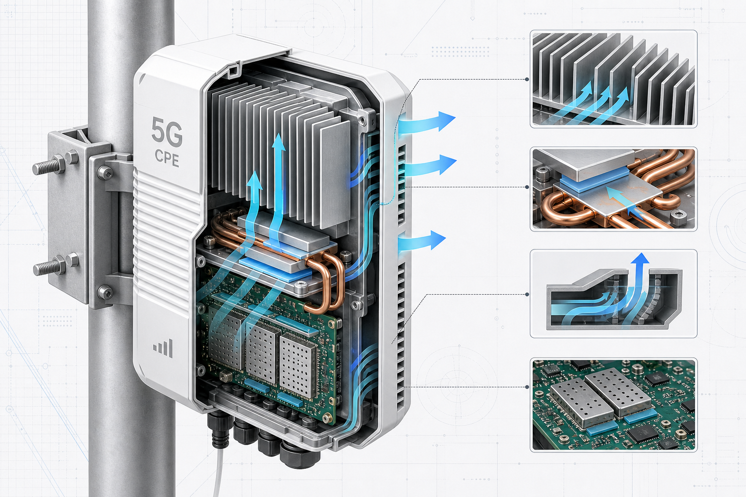
As 5G CPE deployments scale from climate-controlled indoor environments to outdoor poles, rooftop mounts, desert installations, and tropical regions, thermal management has emerged as one of the most critical — and frequently underestimated — engineering disciplines in CPE product design. A 5G CPE that delivers 4 Gbps throughput on a laboratory bench at 25°C may throttle to 400 Mbps when mounted in direct sunlight at 55°C ambient — a performance degradation that directly impacts operator SLAs, customer satisfaction, and field return rates. This article examines the thermal engineering principles, passive cooling strategies, material science considerations, and validation methodologies that B2B buyers should understand when evaluating 5G CPE for outdoor and industrial deployments.
Why 5G CPE Generates More Heat Than LTE CPE
The thermal challenge in 5G CPE is fundamentally more demanding than its LTE predecessors for several interrelated reasons:
- Higher Power Amplifier Output: 5G NR CPE typically operates at Power Class 3 (23 dBm) for sub-6 GHz bands, comparable to LTE. However, the wider channel bandwidths (up to 100 MHz for FR1) and higher-order modulation (256 QAM, with 1024 QAM in 5G-Advanced) demand more linear power amplifier operation, which directly increases PA power consumption and heat generation. A 5G CPE modem-RF subsystem may consume 5–8W under full load, compared to 2–4W for a comparable LTE Cat-12 device.
- Multi-Antenna RF Chains: 4×4 MIMO configurations double the RF chain count compared to 2×2 MIMO LTE CPE. Each additional receive chain adds LNAs (low-noise amplifiers), filters, and ADC circuitry that contribute to the total thermal budget.
- Applications Processor and Wi-Fi Coexistence: Modern 5G CPE integrates Wi-Fi 6/6E chipsets, Ethernet switch fabrics, and increasingly AI/ML inference engines for intelligent traffic management — each representing a discrete heat source within the same sealed enclosure.
- Sealed Enclosure Requirements: Outdoor CPE must achieve IP65 or IP67 ingress protection, which mandates fully sealed enclosures with no ventilation openings. This eliminates the possibility of forced-air cooling and forces all heat dissipation through the enclosure surface.
Passive Cooling Architecture: The Engineering Stack
For outdoor 5G CPE where fan-based active cooling is precluded by reliability and ingress-protection requirements, passive cooling design follows a layered engineering approach:
1. PCB-Level Heat Spreading
The first thermal barrier is at the printed circuit board level. High-power components — the modem-RF SoC, power amplifiers, PMIC (power management IC), and Wi-Fi chipset — are the primary heat sources. Effective PCB thermal design begins with:
- Thermal Vias: Dense arrays of plated through-hole vias directly beneath heat-generating ICs conduct heat from the component junction through the PCB substrate to the bottom copper layer. A typical 5G CPE design may incorporate 100–200 thermal vias beneath the modem SoC alone, each with 0.3 mm diameter and 0.8 mm pitch, filled and capped for optimal thermal conductivity.
- Copper Pour and Thermal Planes: Dedicated internal copper layers (2 oz or 3 oz copper weight) serve as lateral heat spreaders, distributing thermal energy across the PCB area before it reaches the enclosure interface. Multi-layer stackups with dedicated thermal planes can reduce hot-spot temperatures by 8–12°C compared to signal-only stackup designs.
- Component Placement Optimization: High-power components are distributed across the PCB to avoid thermal coupling. The modem SoC, power amplifiers, and Wi-Fi chipset are placed with minimum 15 mm separation and oriented so that their primary heat conduction paths do not overlap on underlying thermal planes.
2. Thermal Interface Materials (TIM)
The junction between heat-generating components and the heatsink or enclosure is a critical thermal resistance point. Material selection here has an outsized impact on overall thermal performance:
- Gap Pads vs. Thermal Paste vs. Phase-Change Materials: Gap pads (silicone or acrylic-based, 1–5 W/m·K thermal conductivity) provide the simplest assembly process but introduce 0.5–2°C/W of interface resistance. Thermal paste (3–8 W/m·K) offers lower resistance but requires controlled dispensing and is less suitable for high-volume manufacturing. Phase-change materials (PCMs) represent an optimal middle ground — solid at room temperature for easy handling, they liquefy at approximately 45–55°C to fill microscopic surface irregularities, achieving thermal resistance comparable to paste while maintaining assembly-line compatibility.
- Graphite and Graphene TIMs: For designs pushing the thermal envelope, synthetic graphite sheets (400–1,500 W/m·K in-plane conductivity) provide exceptional lateral heat spreading between the component and heatsink interface. Emerging graphene-enhanced TIMs offer isotropic conductivity exceeding 10 W/m·K and are beginning to appear in premium outdoor CPE designs.
3. Heatsink and Enclosure Design
The enclosure itself serves as the ultimate heat rejection surface to the ambient environment. Key design parameters include:
- Die-Cast Aluminum Enclosure: Aluminum A380 or ADC12 die-cast alloy provides thermal conductivity of approximately 96 W/m·K at a reasonable material and tooling cost. The enclosure base thickness beneath the PCB mounting area should be at minimum 3–5 mm to provide sufficient thermal mass and lateral conduction.
- External Fin Geometry: The exterior surface area is the limiting factor in passive convection cooling. Vertical fin arrays on the enclosure exterior maximize natural convection airflow — fin height, spacing, and thickness should be optimized using computational fluid dynamics (CFD) simulation. Typical efficient designs achieve 2.5–4× surface area multiplication relative to a smooth enclosure of the same footprint.
- Solar Radiation Management: For outdoor deployments in sunny climates, solar heat gain can add 15–25°C to the effective ambient temperature seen by internal components. White or light-gray powder-coated enclosures with solar reflectance index (SRI) above 80 can reduce solar heat absorption by 30–40% compared to dark-colored or bare metal enclosures. A secondary radiation shield — an outer shell with an air gap of 5–10 mm from the primary enclosure — can further reduce solar heat gain by an additional 10–15°C.
- Mounting Orientation: The enclosure should be designed for vertical pole or wall mounting, which optimizes natural convection airflow along the fin channels. Horizontal mounting reduces convection efficiency by approximately 30–40% and should be avoided in thermal design assumptions unless specifically required by the deployment scenario.
Thermal Simulation and Validation Methodology
B2B buyers evaluating 5G CPE thermal designs should ask vendors about their simulation and validation processes. The industry-standard workflow includes:
- CFD Simulation: Computational fluid dynamics modeling (using tools such as Ansys Icepak, Siemens Flotherm, or COMSOL) simulates conjugate heat transfer — conduction through PCB and enclosure materials combined with natural convection and radiation to the ambient environment. A properly validated CFD model should predict hot-spot temperatures within ±3°C of physical measurements.
- Thermal Chamber Testing: Physical prototypes are tested in environmental chambers across the full operating temperature range (-20°C to +65°C for industrial-grade CPE, with some designs extending to +75°C). Testing includes cold-start behavior (components may not reach operating temperature immediately at -20°C), steady-state thermal soak at temperature extremes, and cyclic thermal shock (-20°C to +65°C ramp at 3°C/minute, 100+ cycles) to validate solder joint and TIM reliability.
- Solar Load Simulation: For outdoor-rated CPE, solar load testing per IEC 60068-2-5 (solar radiation) exposes the enclosure to 1,120 W/m² irradiance while monitoring internal component temperatures. This validates the solar radiation management features of the enclosure design.
- Worst-Case Traffic Load Testing: Thermal performance must be validated under worst-case traffic conditions — simultaneous maximum throughput on all active 5G carriers, maximum Wi-Fi client load, and full Ethernet switch utilization. Many CPE designs pass thermal validation at idle but throttle under combined load. Buyers should request thermal performance data at 100% duty cycle, not just typical usage profiles.
Key Thermal Specifications for B2B RFPs
When issuing RFPs for outdoor or industrial 5G CPE, include the following thermal performance requirements:
| Parameter | Requirement | Verification Method |
|---|---|---|
| Operating Temperature Range | -20°C to +65°C (industrial); -20°C to +55°C (outdoor commercial) | Thermal chamber, full load |
| Throughput at +55°C Ambient | ≥90% of 25°C baseline throughput | iPerf3, 60-minute soak |
| Solar Load Tolerance | No thermal throttling at 1,120 W/m² + 45°C ambient | IEC 60068-2-5 or equivalent |
| Cold Start Time | Full operational within 5 minutes at -20°C | Cold chamber start |
| Cooling Method | Passive (fanless); no moving parts | Visual inspection |
| Enclosure Material | Aluminum alloy, powder-coated, SRI ≥ 80 | Material certification + SRI measurement |
| Thermal Shock Cycles | 100 cycles, -20°C to +65°C, 3°C/min ramp | Post-test functional verification |
The Cost of Inadequate Thermal Design
The financial impact of poor thermal management in 5G CPE manifests across multiple dimensions. Field return rates for outdoor CPE with inadequate thermal design typically run 3–8× higher than properly engineered alternatives, with each RMA representing $50–150 in reverse logistics, refurbishment, and replacement costs. More significantly, thermal-throttled CPE degrades the end-user experience, generating support calls and eroding the operator’s brand reputation — particularly damaging in competitive FWA markets where subscribers can easily switch providers.
For B2B buyers and operators, the thermal design of 5G CPE is not merely a reliability consideration — it is a direct determinant of service quality, operating cost, and competitive differentiation in outdoor and industrial FWA deployments. The engineering investment in proper passive cooling design, validated through rigorous simulation and physical testing, pays for itself many times over through reduced field failures and sustained performance across the product lifecycle.
This technical guide was prepared by the Honlly Telecom engineering team. For inquiries about Honlly’s outdoor-rated 5G CPE products with proven thermal designs for tropical, desert, and industrial environments, contact our sales team at sales@xmhonlly.com.