Author: openclaw-Lisa-New

  • 5G Network Slicing for Enterprise CPE: Commercial Deployments Accelerate in 2026

    5G Network Slicing for Enterprise CPE: Commercial Deployments Accelerate in 2026

    After years of lab demonstrations and limited proof-of-concept deployments, 5G network slicing is entering the commercial mainstream in 2026—and enterprise fixed wireless access (FWA) is emerging as one of its most compelling early use cases. Mobile network operators across Asia-Pacific, Europe, and North America are now launching differentiated FWA service tiers built on 5G standalone (SA) core slicing, creating new revenue opportunities and raising the bar for CPE capability requirements.

    The timing is significant. With global 5G FWA connections projected to surpass 230 million by year-end 2026, operators are under pressure to move beyond flat-rate “best-effort” broadband and offer value-added connectivity products that justify premium pricing. Network slicing provides the technical foundation to do exactly that.

    What 5G Network Slicing Means for Enterprise FWA

    Network slicing allows operators to partition a single physical 5G infrastructure into multiple virtual networks, each with dedicated resources and tailored performance characteristics. For enterprise FWA customers, this translates into guaranteed service-level agreements (SLAs) for throughput, latency, and availability—capabilities that best-effort mobile broadband simply cannot deliver.

    Three primary enterprise FWA slice categories are gaining traction in 2026:

    • Enhanced Mobile Broadband (eMBB) Slice: High-throughput connectivity for general enterprise internet access, cloud applications, and branch office networking. Typically provisioned with 500 Mbps–2 Gbps downlink and 99.9% availability SLAs.
    • Ultra-Reliable Low-Latency (URLLC) Slice: Sub-10 ms latency for industrial automation, remote equipment control, and real-time video analytics. Deployed primarily in manufacturing, logistics, and smart grid applications.
    • Massive IoT (mMTC) Slice: Low-bandwidth, high-density connectivity for sensor networks, asset tracking, and smart building management. Supports thousands of devices per cell with minimal power consumption.

    Leading the commercial charge is South Korea, where SK Telecom and KT launched enterprise-grade slicing on their nationwide 5G SA networks in Q1 2026. Deutsche Telekom followed with a dedicated enterprise FWA slicing product across 14 German cities in March, while Singtel announced commercial slicing availability for enterprise customers across Singapore in April. In the United States, T-Mobile’s 5G SA network now supports enterprise slicing in 18 major metropolitan areas, with Verizon expected to follow by Q4 2026.

    CPE Requirements for Slicing-Aware Deployments

    The shift to sliced enterprise FWA services introduces new CPE procurement considerations for ISPs, MVNOs, and enterprise buyers. Not all 5G CPE devices are slicing-capable. Key requirements include:

    5G SA (Standalone) Modem Support: Network slicing requires a 5G SA core; NSA (non-standalone) architectures cannot support end-to-end slicing. CPE must integrate a 3GPP Release 16 or later modem with full SA capability, including support for Network Slice Selection Assistance Information (NSSAI) parameters.

    Multi-Slice Concurrent Connectivity: Enterprise-grade CPE must support simultaneous attachment to multiple slices—for example, maintaining an eMBB slice for general office traffic while concurrently using a URLLC slice for industrial control systems. This requires URSP (UE Route Selection Policy) support at the modem and application layers.

    Slice-Aware QoS Mapping: The CPE must be capable of mapping internal traffic classes (VLANs, DSCP markings, application signatures) to appropriate 5G QoS Identifiers (5QIs) and slice identifiers. This ensures that latency-sensitive traffic is routed through the URLLC slice while bulk data traverses the eMBB slice.

    Management Plane Integration: Slicing-aware CPE should integrate with operator slice orchestration platforms via standardized APIs. TR-369 (USP) with slicing extensions is emerging as the preferred management protocol, enabling operators to dynamically provision, modify, and decommission slices on deployed CPE without truck rolls.

    Market Outlook: A $4.2 Billion CPE Opportunity by 2028

    ABI Research estimates that slicing-compatible enterprise CPE shipments will grow from approximately 380,000 units in 2026 to over 2.8 million units annually by 2028, representing a cumulative addressable market of $4.2 billion. The strongest demand is expected from the manufacturing, logistics, healthcare, and energy verticals, where guaranteed wireless SLAs can replace or augment costly fiber deployments.

    For CPE OEMs and ODMs, the window to develop and certify slicing-capable product lines is narrowing. Early movers who deliver carrier-tested, multi-slice-capable devices with integrated URSP support will be well-positioned to capture premium pricing as operators scale their enterprise slicing offerings through 2027.

    FAQ

    What is 5G network slicing for enterprise CPE?

    5G network slicing creates dedicated virtual network partitions within a single 5G infrastructure, each optimized for specific enterprise use cases. Enterprise CPE devices connect to these slices to receive guaranteed throughput, latency, and reliability SLAs tailored to different application requirements.

    Which 5G CPE modems support network slicing?

    CPE must integrate a 3GPP Release 16 or later 5G SA modem with NSSAI and URSP support. Qualcomm’s Snapdragon X65/X70/X75 and MediaTek’s T750/T830 platforms are among the commercially available chipsets with confirmed slicing capability.

    Can existing 5G CPE devices be upgraded for slicing?

    In most cases, no. Network slicing requires 5G SA modem hardware support at the chipset level. Firmware updates on NSA-only devices cannot add slicing capability. Operators and enterprises planning slicing deployments should verify SA + URSP capability in their CPE procurement specifications.

    When will network slicing be widely available for enterprise FWA?

    Commercial availability is accelerating in 2026, particularly in South Korea, Germany, Singapore, and select US markets. Wider availability across additional operators and regions is expected through 2027 as 5G SA core deployments expand.

    Interested in slicing-compatible 5G CPE for your enterprise or operator deployment? Contact Honlly Telecom to discuss our 5G SA-capable CPE portfolio with full URSP and multi-slice support.
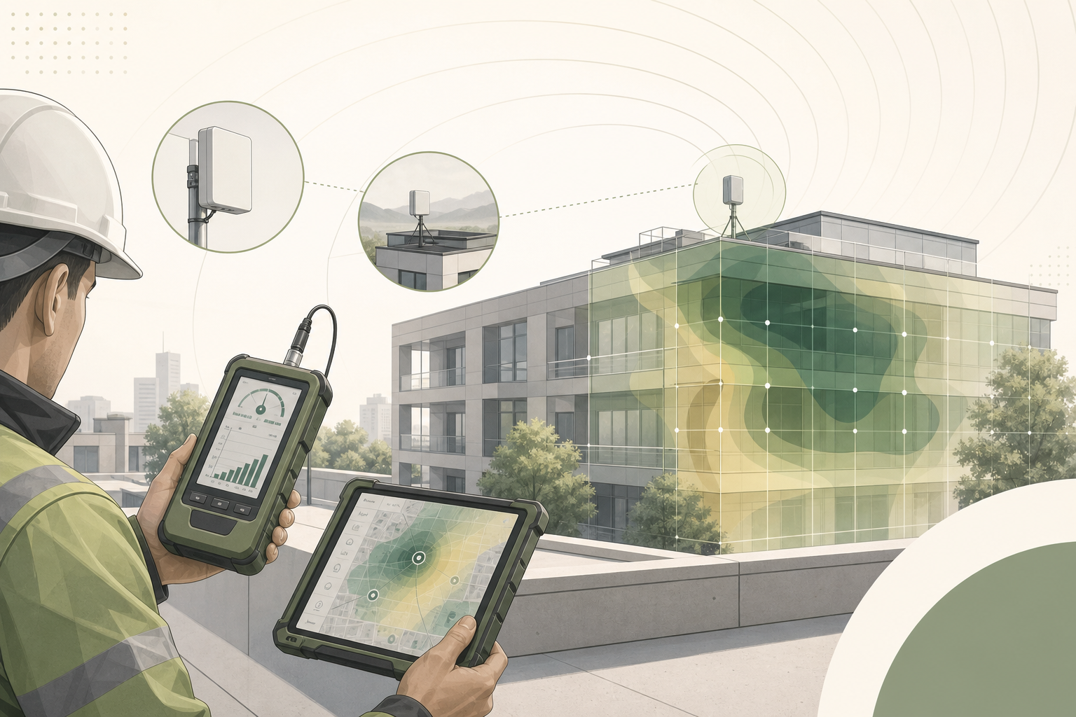

  • A Field Engineer’s Guide to 5G FWA Site Survey and CPE Installation: From Signal Measurement to Throughput Verification

    A Field Engineer’s Guide to 5G FWA Site Survey and CPE Installation: From Signal Measurement to Throughput Verification

    A properly executed site survey is the single most important factor determining whether a 5G fixed wireless access (FWA) deployment delivers the throughput and reliability your customers expect—or generates a steady stream of support tickets. Yet in the rush to scale FWA rollouts, many operators and integrators shortcut this critical step, relying on coverage maps and best-guess antenna placement rather than methodical field measurements.

    This guide provides a structured, repeatable methodology for 5G FWA site surveys and outdoor CPE installation. It is designed for field engineers, deployment managers, and technical teams at ISPs, operators, and system integrators who need to deliver consistent installation quality at scale.

    Phase 1: Pre-Installation Preparation

    1.1 Tools and Equipment Checklist

    Before heading to the site, ensure your field kit includes:

    • Spectrum/signal analyzer: A handheld 5G NR-capable analyzer supporting FR1 (sub-6 GHz) and, if applicable, FR2 (mmWave) bands. Rohde & Schwarz, Keysight, and Anritsu offer field-portable options. For budget-constrained operations, smartphone-based tools like G-NetTrack Pro or NSG can provide adequate baseline measurements when calibrated against a reference device.
    • Candidate CPE device: The exact CPE model planned for deployment, loaded with engineering firmware that exposes RSRP, RSRQ, SINR, and PCI readings. Generic measurement tools cannot substitute for the actual CPE’s antenna and modem characteristics.
    • Mounting test pole: A telescoping pole (3–6 meters) with temporary bracket for testing antenna positions at planned mounting heights.
    • GPS receiver or smartphone: For recording precise coordinates and azimuth angles at each test position.
    • Laptop/tablet: Running iPerf3 or equivalent for throughput testing, plus a spreadsheet or survey app for structured data capture.
    • Compass and inclinometer: For recording antenna azimuth and tilt angles.
    • Weather-appropriate PPE: Harness, helmet, gloves for rooftop work; sun protection for extended outdoor surveys.

    1.2 Pre-Survey Intelligence Gathering

    Before leaving the office, collect the following information:

    • Operator coverage maps: Download the latest 5G coverage data for the target address. Note the nearest cell site locations, azimuth directions, and estimated distances.
    • Spectrum bands deployed: Identify which NR bands (n78, n41, n77, n1, n3, n28, etc.) are active at the target location and their channel bandwidths. This determines whether the deployment will leverage mid-band capacity or rely on low-band coverage.
    • Site photographs (Google Earth/Street View): Preview the building orientation, roofline, surrounding structures, and potential obstructions (trees, adjacent buildings, water towers).
    • Customer requirements: Confirmed throughput targets (downlink and uplink), number of concurrent users, application profile (e.g., general internet vs. VoIP/video conferencing vs. industrial IoT), and any specific SLA commitments.

    Phase 2: On-Site Signal Survey

    2.1 Exterior Signal Assessment

    Begin with a walk-around survey of the building exterior. The goal is to identify the optimal azimuth direction and mounting position before committing to a fixed installation.

    Step 1 — Perimeter Scan: Walk a complete circuit of the building at ground level, stopping every 5–10 meters to record RSRP, RSRQ, and SINR values from the candidate CPE. Hold the device at arm’s length, oriented toward the exterior wall, and rotate through 360° at each position. Record the best and worst azimuths.

    Step 2 — Rooftop/Balcony Assessment: If accessible, repeat the perimeter scan at the planned mounting height. Signal quality at 5 meters above ground can differ dramatically from ground-level readings, particularly in urban environments with street-level canyon effects. Use the test pole to simulate the final antenna position.

    Step 3 — Line-of-Sight Verification: For deployments targeting mmWave or high-frequency mid-band (n78/n77), visually confirm line-of-sight to the serving cell site. Even partial obstructions—building corners, tree canopies, signage—can cause 10–20 dB of signal attenuation at frequencies above 3.5 GHz. Use binoculars or a camera with telephoto lens if the cell site is not visible to the naked eye.

    2.2 Signal Quality Thresholds

    Record and evaluate measurements against these recommended minimum thresholds for a production-grade 5G FWA installation:

    MetricExcellentGoodAdequateUnacceptable
    RSRP (dBm)> −85−85 to −95−95 to −105< −105
    RSRQ (dB)> −10−10 to −15−15 to −18< −18
    SINR (dB)> 2010 to 205 to 10< 5

    If the best measured position falls into the “Adequate” range, consider whether a higher-gain directional antenna or an alternative mounting location can improve signal quality. “Unacceptable” readings indicate that the site may require an outdoor CPE with high-gain antenna array, a different operator’s service, or should be deferred until network densification improves coverage.

    Phase 3: Antenna Positioning and Optimization

    3.1 Directional Antenna Alignment

    For outdoor CPE with integrated or external directional antennas, precise alignment toward the serving cell is critical. A 10° misalignment on a high-gain antenna can reduce received signal strength by 3–6 dB.

    Alignment Procedure:

    1. Identify the Physical Cell ID (PCI) of the strongest detected cell.
    2. Using the pre-survey cell site location data, calculate the azimuth bearing from the installation site to the target cell.
    3. Mount the CPE temporarily on the test pole at the planned height and position.
    4. Slowly sweep the azimuth ±30° from the calculated bearing while monitoring real-time RSRP and SINR.
    5. Lock the azimuth at the position yielding the highest SINR—not necessarily the highest RSRP. SINR is the stronger predictor of achievable throughput.
    6. Adjust tilt (elevation) to fine-tune, especially if the cell site is at a significantly different elevation.

    3.2 MIMO Antenna Considerations

    Modern 5G CPE devices typically implement 2×2 or 4×4 MIMO. For external antenna installations, ensure:

    • Antenna elements are separated by at least λ/2 (approximately 4.3 cm at 3.5 GHz) to maintain spatial diversity.
    • Cross-polarized antenna pairs (+45°/−45°) are oriented correctly to match the cell site’s polarization configuration.
    • Multiple antenna panels are pointed at the same serving cell—splitting across different cells can degrade MIMO rank and reduce throughput.

    Phase 4: Throughput Verification

    4.1 Benchmark Testing Protocol

    Once the CPE is positioned at the optimal location, conduct structured throughput tests before finalizing the installation:

    1. Idle Throughput Test: Run iPerf3 TCP for 60 seconds with no other traffic on the link. Record average and 95th percentile throughput in both downlink and uplink directions.
    2. Concurrent Load Test: Simulate the expected multi-user scenario by running 3–5 parallel iPerf3 TCP streams. This stresses the CPE’s buffer management and reveals throughput degradation under concurrent load.
    3. Latency Under Load Test: Run continuous ICMP pings (1-second interval) to a nearby server while the iPerf3 TCP test is active. Document the increase in RTT compared to idle conditions. Bufferbloat exceeding 50 ms of added latency warrants QoS tuning on the CPE.
    4. Stability Test: Monitor RSRP, SINR, and PCI for a minimum of 15 minutes. Look for cell reselection events, signal fluctuations exceeding ±5 dB, or PCI changes that indicate handover to a weaker cell.

    4.2 Acceptance Criteria

    A 5G FWA installation meets acceptance criteria when:

    • Downlink throughput ≥80% of the operator’s advertised speed tier for the site location.
    • SINR remains stable within a 5 dB band over the observation period.
    • No cell reselection or PCI changes during the stability test.
    • Latency under load does not increase by more than 30 ms over idle RTT.

    Document all measurements with timestamps, GPS coordinates, and photographs of the final installation. This data is invaluable for troubleshooting future performance issues and demonstrating installation quality to customers.

    Phase 5: Common Pitfalls and Troubleshooting

    SymptomLikely CauseRemediation
    Good RSRP but poor SINRStrong interference from adjacent cell or non-cellular sourceAdjust azimuth to favor serving cell; consider band-locking to a cleaner channel
    Good signal but low throughputCell congestion or backhaul limitationTest at off-peak hours to isolate; escalate to operator if confirmed
    Frequent PCI changesPing-pong handover between cells of similar strengthPCI lock on CPE; adjust antenna to increase dominance of preferred cell
    High latency under loadBufferbloat on CPE or operator core networkEnable AQM/CoDel on CPE; apply traffic shaping below link capacity
    Uplink significantly below expectationsTDD frame configuration favors downlink; low UE transmit powerVerify TDD pattern with operator; reposition CPE to reduce uplink path loss

    Site Survey Documentation Checklist

    Complete this checklist for every installation and attach it to the deployment record:

    • ☐ Site address and GPS coordinates
    • ☐ Installer name and date
    • ☐ Operator and service plan details
    • ☐ CPE model, firmware version, and IMEI
    • ☐ Best-position measurements: RSRP ____ dBm | RSRQ ____ dB | SINR ____ dB | PCI ____
    • ☐ Final antenna azimuth: ____ ° | Tilt: ____ ° | Mounting height: ____ m
    • ☐ Throughput test results: DL ____ Mbps | UL ____ Mbps | Latency (idle) ____ ms | Latency (load) ____ ms
    • ☐ Stability observation period: ____ minutes | PCI changes: ____
    • ☐ Photographs: Installation position, surrounding environment from antenna perspective, CPE mounting detail
    • ☐ Customer sign-off

    FAQ

    What is the most common mistake in 5G FWA site surveys?

    The most frequent error is relying solely on smartphone-based signal readings rather than testing with the actual CPE device that will be deployed. Smartphone antennas, modem capabilities, and MIMO configurations differ significantly from dedicated FWA CPE, often producing misleading signal quality estimates.

    How long should a typical 5G FWA site survey take?

    A thorough residential or small-business survey typically takes 45–90 minutes, including perimeter scans, rooftop assessment, antenna alignment optimization, and throughput verification. Large enterprise or multi-floor installations may require 2–4 hours.

    Can I use a drone for rooftop signal assessment?

    Yes, drone-based surveys are increasingly common for multi-story buildings and industrial sites where rooftop access is restricted. However, drone-mounted measurement equipment must be lightweight and the surveyor must account for drone body effects on antenna patterns. Always comply with local aviation regulations.

    What should I do if no position meets the minimum signal thresholds?

    Consider these escalation options: (1) install an outdoor CPE with a higher-gain directional antenna array, (2) explore external antenna options with longer cable runs to reach a better signal position, (3) evaluate an alternative operator’s coverage at the site, or (4) defer the installation and flag the address for network densification review.

    Looking for carrier-grade 5G FWA CPE with flexible antenna options for your deployment projects? Contact Honlly Telecom to discuss our outdoor and indoor 5G CPE portfolio, including models with external antenna support and engineering-mode diagnostic access for professional site surveys.

  • 5G NR-U (NR in Unlicensed Spectrum) for Enterprise CPE: A Technical Guide to License-Assisted Access, Standalone NR-U, and Private Network Deployment Architectures

    5G NR-U (NR in Unlicensed Spectrum) for Enterprise CPE: A Technical Guide to License-Assisted Access, Standalone NR-U, and Private Network Deployment Architectures

    As the global demand for private wireless networks accelerates, enterprises and system integrators are increasingly exploring spectrum options beyond traditional licensed bands. 5G NR-U (New Radio in Unlicensed Spectrum) has emerged as a compelling alternative, offering the performance characteristics of 5G NR without the cost and complexity of spectrum licensing. For operators, MVNOs, and enterprise IT buyers evaluating CPE deployments, understanding the NR-U landscape is essential to making informed architecture decisions in 2026.

    This technical guide provides a comprehensive overview of 5G NR-U technology, its deployment architectures, and practical considerations for CPE selection. Whether you are planning a private 5G network for a manufacturing campus, a neutral host deployment in a multi-tenant building, or a cost-optimized FWA rollout in unlicensed spectrum, the information below will help you navigate the technology and procurement landscape.

    Understanding 5G NR-U: LAA vs Standalone NR-U

    3GPP defined two operational modes for 5G NR in unlicensed spectrum, each serving distinct deployment scenarios:

    License-Assisted Access (LAA): Specified in 3GPP Release 15 and enhanced in Release 16, LAA requires an anchor carrier in licensed spectrum. The primary cell (PCell) operates in licensed bands, while one or more secondary cells (SCells) aggregate unlicensed carriers to boost throughput. This model is well-suited for operators who already hold licensed spectrum and want to augment capacity in high-density areas. LAA-capable CPE must support carrier aggregation across licensed and unlicensed bands, which adds modem complexity but preserves the reliability of licensed-spectrum control signaling.

    Standalone NR-U (sNR-U): Introduced in 3GPP Release 16, sNR-U operates entirely in unlicensed spectrum without requiring a licensed anchor. This is the architecture of choice for private 5G networks, enterprise campus deployments, and neutral host networks where the deploying organization does not hold spectrum licenses. sNR-U CPE must implement robust coexistence mechanisms—primarily Listen-Before-Talk (LBT)—to share spectrum fairly with Wi-Fi and other unlicensed technologies.

    For CPE procurement, the choice between LAA and sNR-U has significant implications for modem selection, antenna design, and certification requirements. LAA CPE benefits from the mature ecosystem of licensed-band 5G modems, while sNR-U CPE requires chipsets with dedicated unlicensed-band RF front-ends and LBT firmware support.

    Spectrum Options: 5 GHz, 6 GHz, and the Global Regulatory Landscape

    The availability of unlicensed spectrum for NR-U operation varies by region, and CPE hardware must be configured accordingly:

    • 5 GHz Band (5.15–5.925 GHz): The most universally available unlicensed band, already shared by Wi-Fi 5, Wi-Fi 6, and Wi-Fi 6E. NR-U in 5 GHz must coexist with existing Wi-Fi deployments, which is technically feasible through LBT but practically challenging in Wi-Fi-dense environments. Most first-generation sNR-U CPE targets the 5 GHz band due to broad regulatory approval.
    • 6 GHz Band (5.925–7.125 GHz): The “greenfield” unlicensed spectrum opened by regulators in the US (FCC), Europe (CEPT), and select Asia-Pacific markets. With 1,200 MHz of bandwidth available, the 6 GHz band offers significantly more capacity for NR-U deployments. However, regulatory frameworks differ: the US permits unlicensed use across the full band, while Europe and other regions have implemented portions as license-exempt with varying power limits. CPE targeting multi-region deployment must support configurable band masks and power profiles.
    • mmWave Unlicensed (57–71 GHz): While technically available for NR-U, mmWave unlicensed bands present practical challenges for CPE due to propagation limitations and the need for beamforming. Most NR-U CPE development through 2026 focuses on sub-7 GHz bands.

    CPE buyers should verify that target devices support the specific unlicensed band allocations in their deployment region, including DFS (Dynamic Frequency Selection) compliance where required for 5 GHz operation.

    Architectural Models for NR-U Enterprise CPE Deployment

    NR-U supports several deployment architectures that are relevant to enterprise and operator CPE procurement:

    Standalone Private 5G (SNPN): A fully self-contained 5G network operating exclusively in unlicensed spectrum, using sNR-U for both the radio access network and device connectivity. This model is ideal for industrial campuses, logistics centers, and enterprise facilities where the organization controls both the network infrastructure and CPE endpoints. CPE for SNPN deployments should support network slicing to isolate traffic classes and URLLC features for time-sensitive industrial applications.

    Neutral Host Network (NHN): A shared radio access infrastructure deployed by a third-party neutral host provider, serving multiple tenant operators or enterprises from a common NR-U RAN. CPE in NHN architectures must support multi-PLMN selection and potentially eSIM-based credential management to facilitate tenant onboarding and mobility between shared and dedicated spectrum resources.

    Hybrid Licensed-Unlicensed Aggregation: Operators with licensed spectrum holdings can deploy CPE that aggregates licensed carriers (for control plane reliability and baseline coverage) with NR-U carriers (for capacity augmentation). This hybrid model is popular among Tier-2 and Tier-3 operators seeking to expand FWA capacity without additional spectrum acquisition costs.

    Coexistence Mechanisms: LBT and Shared Spectrum Efficiency

    The defining technical challenge of NR-U is fair coexistence with Wi-Fi and other unlicensed spectrum users. 3GPP specified several mechanisms to ensure NR-U operates as a “good neighbor” in shared spectrum:

    Listen-Before-Talk (LBT): The foundational coexistence mechanism, requiring NR-U transmitters to sense the channel for a defined period before transmission. If the channel is occupied, the transmitter defers access using a contention window that doubles on collision, similar to Wi-Fi’s CSMA/CA protocol. 3GPP defined two LBT categories—Category 2 (fixed sensing period without random backoff) and Category 4 (variable contention window with exponential backoff)—with Category 4 being the default for data transmission.

    Channel Occupancy Time (COT) Sharing: NR-U allows a gNB that has acquired the channel to share its COT with connected CPE devices, reducing the number of LBT operations required and improving overall spectral efficiency. Intelligent COT scheduling is critical to NR-U performance, as excessive LBT overhead can negate the throughput advantages of 5G NR over Wi-Fi.

    Wideband Operation with Sub-Band LBT: For deployments using wide carriers (40 MHz, 80 MHz, or 100 MHz), NR-U supports sub-band LBT where the carrier is divided into 20 MHz sub-bands, each independently subject to LBT. If interference is detected on one sub-band, the transmission can proceed on others, providing resilience in congested spectrum environments.

    Private 5G Networks with NR-U: A Cost-Effective Path

    For enterprises evaluating private 5G, NR-U offers a significantly lower barrier to entry compared to licensed-spectrum deployments. The elimination of spectrum licensing fees—which can range from $50,000 to multiple millions depending on country and bandwidth—makes private 5G accessible to mid-market enterprises that previously could not justify the investment.

    However, CPE buyers should understand the trade-offs. NR-U networks in shared spectrum do not offer the same interference guarantees as licensed-spectrum private 5G. In busy industrial environments with heavy Wi-Fi usage, NR-U performance may degrade during peak Wi-Fi activity. System integrators should conduct thorough site surveys and RF planning before committing to an all-NR-U architecture, and consider hybrid models that reserve licensed spectrum for critical control traffic while offloading bulk data to NR-U carriers.

    Device ecosystem maturity is another consideration. While the number of NR-U-capable CPE and module vendors is growing rapidly in 2026, the ecosystem is smaller than that for licensed-band 5G. Buyers should verify NR-U interoperability with their chosen small cell or gNB vendor before procurement.

    CPE Hardware Requirements for NR-U Support

    NR-U-capable CPE requires specific hardware capabilities beyond standard 5G NR CPE:

    • Unlicensed-band RF Front-End: Dedicated receive and transmit chains covering 5 GHz and/or 6 GHz unlicensed bands, with sufficient linearity and filtering to operate in shared spectrum without causing or receiving adjacent-channel interference.
    • LBT Firmware: CPE modem firmware must implement 3GPP-compliant LBT procedures, including energy detection threshold configuration, contention window management, and COT sharing logic. LBT performance directly impacts NR-U throughput, making modem firmware quality a key procurement criterion.
    • DFS/Radar Detection: CPE operating in 5 GHz DFS channels must implement radar detection and dynamic frequency selection, vacating channels when radar signals are detected. This requires both hardware detection capability and regulatory certification in each target market.
    • Multi-band Carrier Aggregation: For hybrid deployment models, the CPE modem must support carrier aggregation combining licensed and unlicensed component carriers, with independent RF chains for each band.
    • GNSS/1588 Timing: NR-U TDD operation requires precise timing synchronization. CPE should support either GNSS-disciplined oscillators or IEEE 1588v2 Precision Time Protocol for phase alignment across the network.

    Honlly’s NR-U-Ready CPE Portfolio

    Honlly Telecom is actively developing NR-U-capable CPE platforms targeting the enterprise private 5G and neutral host deployment markets. The next-generation HL-860 series platform, sampling in Q3 2026, will feature native support for sNR-U operation in the 5 GHz and 6 GHz bands, with integrated LBT firmware, DFS radar detection, and multi-band carrier aggregation across licensed and unlicensed spectrum. Engineering samples and technical specifications are available to qualified operator and system integrator partners under NDA.

    For procurement teams planning private 5G or NR-U-enhanced FWA deployments, Honlly’s solutions engineering team offers consultation on CPE selection, network architecture, and RF planning. Contact sales@xmhonlly.com to discuss your NR-U deployment requirements and receive a tailored CPE recommendation.

    Key Takeaways for CPE Buyers:

    • NR-U offers a cost-effective path to private 5G without spectrum licensing fees
    • Choose between LAA (licensed anchor required) and sNR-U (fully unlicensed) based on spectrum availability and deployment model
    • Verify CPE band support, LBT firmware quality, and DFS certification for target deployment regions
    • Conduct RF site surveys to assess Wi-Fi coexistence risk before committing to sNR-U architecture
    • Hybrid licensed-unlicensed aggregation provides the best balance of reliability and capacity for operator deployments
  • AI-Native CPE Management Enters Commercial Phase in 2026: How Machine Learning Is Transforming RF Optimization and Predictive Maintenance for 5G Fixed Wireless Access Networks

    AI-Native CPE Management Enters Commercial Phase in 2026: How Machine Learning Is Transforming RF Optimization and Predictive Maintenance for 5G Fixed Wireless Access Networks

    The telecom industry is witnessing a paradigm shift in how customer premises equipment (CPE) is managed at scale. After years of lab trials and proof-of-concept deployments, AI-native CPE management solutions are entering commercial service in 2026, bringing machine learning (ML)-driven automation to routine RF optimization, interference mitigation, and predictive maintenance workflows. For ISPs and mobile network operators managing tens of thousands of 5G fixed wireless access (FWA) endpoints, this transition from reactive troubleshooting to proactive intelligence marks one of the most significant operational efficiency gains since the introduction of TR-069 auto-configuration servers two decades ago.

    The commercial availability of AI-native CPE management coincides with the global FWA subscriber base surpassing 200 million connections in mid-2026. As operators scale their deployments, the operational burden of manual CPE configuration, spectrum re-planning, and fault diagnosis becomes unsustainable. AI-driven platforms are emerging as the answer, leveraging telemetry data from deployed CPE fleets to automate optimization tasks that previously required field engineer visits.

    The Shift from Reactive to Predictive CPE Management

    Traditional CPE management architectures rely on periodic polling via TR-069 or TR-369 (USP) protocols. While effective for bulk configuration and firmware updates, these frameworks operate on fixed intervals and lack the ability to anticipate degradation before it impacts subscriber experience. In a 5G FWA network where each CPE serves as a primary broadband connection for a household or enterprise branch, even brief periods of degraded performance translate directly into support tickets and churn risk.

    AI-native platforms invert this model. Instead of waiting for threshold breaches, they continuously ingest real-time metrics—RSRP, RSRQ, SINR, BLER, MCS index, and throughput per bearer—from every CPE in the fleet. Transformer-based time-series models then detect subtle pattern shifts that precede observable faults by hours or even days. The result is a predictive maintenance capability that allows operators to remediate issues before subscribers notice them.

    Major CPE silicon vendors, including Qualcomm and MediaTek, have begun exposing ML inference APIs on their 5G modem platforms, enabling on-device anomaly detection that feeds into cloud-based fleet intelligence. This edge-cloud hybrid architecture reduces backhaul overhead while maintaining centralized visibility across the entire subscriber base.

    ML-Driven RF Optimization: Beyond Static Configuration

    Perhaps the most transformative application of AI in CPE management is autonomous RF optimization. In dense urban FWA deployments, where dozens of CPE devices operate within overlapping coverage footprints, static antenna configuration and fixed channel assignment lead to persistent co-channel interference and suboptimal spectral efficiency.

    Reinforcement learning (RL) models trained on field data can now dynamically adjust CPE parameters—antenna beam steering, carrier aggregation band selection, MIMO layer mapping, and power control—in response to real-time RF conditions. Field trials conducted by Tier-1 operators in Southeast Asia and the Middle East have demonstrated 18–27% throughput improvements in high-interference environments when ML-driven optimization replaced manual configuration.

    The commercial availability of these capabilities in 2026 is being accelerated by the maturation of O-RAN Alliance specifications, which define standardized interfaces for RAN Intelligent Controller (RIC) integration. Non-real-time RIC (Non-RT RIC) platforms can now ingest CPE-level telemetry and push optimization policies through the rApps framework, creating a vendor-agnostic AI management layer that works across multi-supplier CPE deployments.

    Predictive Fault Detection and Self-Healing Networks

    Beyond RF optimization, AI-native platforms are proving their value in fault management. CPE hardware failures—antenna degradation, PA burnout, thermal throttling, memory leaks—often present early warning signs in telemetry data long before they cause a complete outage. ML classifiers trained on historical failure data can identify these precursors with over 90% accuracy, enabling proactive CPE replacement or remote reconfiguration.

    Self-healing capabilities represent the next maturity stage. When an AI platform detects a degrading CPE, it can automatically attempt remediation—switching to an alternative serving cell, reducing MIMO layers to compensate for antenna path loss, or throttling throughput to manage thermal headroom—before escalating to a truck roll. For operators, each avoided field visit represents an estimated $150–$300 in operational savings, making the ROI case for AI-native management compelling even at moderate fleet sizes.

    What This Means for ISP Procurement in 2026–2027

    As AI-native management enters commercial service, CPE procurement criteria are evolving. Forward-looking ISPs and operators are now evaluating CPE platforms not just on RF performance and cost, but on their telemetry richness and AI integration readiness. Key procurement considerations include:

    • Telemetry granularity: Does the CPE expose per-bearer metrics, per-antenna-path RSSI, and modem temperature at sub-second intervals?
    • On-device ML capability: Does the platform support edge inference via Qualcomm AI Engine, MediaTek APU, or equivalent NPU hardware?
    • Standards alignment: Is the CPE compatible with O-RAN O1 and A1 interfaces for RIC integration?
    • Vendor API openness: Does the manufacturer provide RESTful or gRPC APIs for telemetry streaming and configuration push?
    • Fleet scalability: Can the AI platform handle 100,000+ devices with sub-second latency for critical remediation events?

    Distributors and system integrators serving the ISP market should anticipate growing demand for AI-ready CPE and build their 2026–2027 product portfolios accordingly. The operational cost savings alone justify a premium of 8–12% over conventional CPE, and the subscriber experience improvements translate into measurable reductions in churn.

    Honlly’s AI-Ready CPE Portfolio

    Honlly Telecom’s 5G FWA CPE product line—including the HL-810Z, HL-820Z, and the newly launched HL-850Z WiFi 7 platform—is engineered for AI-native fleet management. All current-generation devices support high-granularity telemetry export via TR-369 USP, with O-RAN O1 interface compatibility currently in field validation. Honlly’s engineering team works closely with operator partners to customize telemetry schemas and integrate CPE data pipelines into their chosen AI/ML operations platforms.

    For ISP procurement teams evaluating AI-ready CPE for 2026–2027 deployment cycles, Honlly offers evaluation units, technical documentation, and integration support. Contact the Honlly sales engineering team to schedule a technical consultation and discuss your AI-native FWA roadmap.

  • 5G CPE Total Cost of Ownership Analysis for ISP Procurement: CAPEX, OPEX, and Lifecycle Economics for Fixed Wireless Access Rollouts

    5G CPE Total Cost of Ownership Analysis for ISP Procurement: CAPEX, OPEX, and Lifecycle Economics for Fixed Wireless Access Rollouts

    For ISPs and telecom operators planning Fixed Wireless Access (FWA) rollouts, the per-unit purchase price of a 5G CPE represents only the tip of the financial iceberg. A comprehensive Total Cost of Ownership (TCO) analysis — spanning hardware acquisition, deployment logistics, ongoing operations, lifecycle management, and end-of-life disposal — often reveals that the initial CAPEX decision accounts for less than 35% of the total five-year cost per subscriber. This guide provides a structured TCO framework for procurement teams evaluating 5G CPE options in 2026.

    The Five-Year TCO Model: Beyond the Unit Price

    A robust 5G CPE TCO model for ISP deployments should account for the following cost categories across a five-year device lifecycle:

    TCO CategoryTypical Share of 5-Year CostKey Variables
    Hardware CAPEX30–35%Unit price, volume discounts, import duties, logistics
    Deployment & Installation12–18%Truck roll cost, self-install ratio, activation failure rate
    Ongoing Operations25–30%Support tickets, firmware updates, ACS platform costs
    Returns & Replacements8–12%DOA rate, field failure rate, warranty terms, RMA logistics
    End-of-Life Management3–5%Reverse logistics, refurbishment, e-waste compliance
    Network/Core Integration5–8%ACS licensing, TR-069/TR-369 server scaling, integration engineering

    This distribution highlights a critical insight: choosing a CPE based primarily on the lowest unit price often increases total cost when deployment complexity, support burden, and failure rates are factored in.

    CAPEX Deep Dive: What Drives the Unit Price

    The bill-of-materials (BOM) cost of a 5G CPE in 2026 is dominated by four components:

    Modem-RF Platform (35–45% of BOM)

    The choice between Qualcomm Snapdragon X75/X80, MediaTek T830, or UNISOC V516 platforms significantly impacts both upfront cost and long-term performance. Qualcomm platforms command a $12–18 premium but offer broader carrier certification coverage and longer software support commitments (typically 5+ years). MediaTek’s T830 provides competitive performance at 15–20% lower cost, making it attractive for price-sensitive markets. UNISOC platforms serve the sub-$60 BOM segment for basic connectivity use cases.

    Wi-Fi Subsystem (8–12% of BOM)

    Wi-Fi 7 (802.11be) chipsets add approximately $15–22 over Wi-Fi 6 equivalents. However, operators deploying Wi-Fi 7 CPE report 18–22% fewer in-home coverage-related support calls, translating to annual OPEX savings of $3–5 per subscriber. For deployments exceeding 50,000 units, the Wi-Fi 7 premium typically pays back within 14–18 months through reduced support costs alone.

    Memory and Storage (6–9% of BOM)

    5G CPE typically requires 512 MB–1 GB LPDDR4X RAM and 256 MB–512 MB flash storage. Operators planning to deploy value-added services (VPN termination, edge compute containers, local traffic analytics) should specify 1 GB RAM minimum to avoid premature obsolescence and costly field replacements.

    Enclosure and Thermal Design (5–8% of BOM)

    Passive thermal design quality directly correlates with field failure rates. CPE using extruded aluminum heatsinks and optimized airflow paths typically show 40–60% lower failure rates over five years compared to plastic-only enclosures with basic ventilation. The $1.50–3.00 incremental BOM cost for improved thermal design is among the highest-ROI investments in CPE specification.

    OPEX: The Hidden Cost Multiplier

    Self-Install vs. Truck Roll Economics

    The single largest OPEX variable in FWA CPE deployment is the self-install success rate. Operators achieving self-install rates above 85% report average deployment costs of $18–35 per subscriber. Those relying primarily on technician visits face $85–150 per installation. Key CPE design factors that improve self-install success include:

    • Guided setup mobile apps with signal-strength-based placement optimization (reduces install failure by 35–40%)
    • eSIM-based zero-touch provisioning eliminating manual APN and carrier configuration (reduces support calls by 22–28%)
    • LED-free “stealth” design options for residential deployments where blinking lights trigger unnecessary support inquiries

    Support Ticket Economics

    Industry benchmarks show that the average 5G FWA CPE generates 0.8–1.4 support contacts per year. At an average cost of $12–18 per handled ticket (including L1 and L2 support), annual per-subscriber support costs range from $9.60 to $25.20. CPE with integrated remote diagnostics capabilities (TR-369 USP-based performance monitoring, Wi-Fi experience scoring) reduce ticket volume by 30–40%.

    Firmware Lifecycle Management

    Over a five-year lifecycle, a typical 5G CPE receives 8–15 firmware updates. Each OTA update carries bandwidth costs ($0.02–0.08 per device per update depending on payload size) and engineering costs for testing and staged rollout management. Operators should verify that CPE vendors commit to a minimum 5-year firmware support window and provide FOTA (Firmware Over-The-Air) delta update capability to minimize bandwidth consumption.

    Returns, RMAs, and Field Failure: The Cost of Unreliability

    Field failure rates for 5G CPE in the first 12 months currently average 2.5–5.0% across the industry, with best-in-class models achieving sub-1.5%. Each field failure incurs:

    • Customer support handling: $15–25 (troubleshooting, diagnosis)
    • Replacement unit cost: 100% of unit price (plus shipping)
    • Reverse logistics: $8–15 (return shipping, receiving, testing)
    • Customer churn risk: 15–25% of subscribers experiencing CPE failure churn within 60 days, representing $250–600 in lost lifetime value per churned subscriber

    For a 100,000-subscriber deployment, a 2% improvement in annual failure rate (from 4% to 2%) translates to approximately $1.2–1.8 million in annual savings — far exceeding any upfront unit price premium for higher-quality CPE.

    TCO Optimization Framework: Six Decision Criteria

    When evaluating 5G CPE options, procurement teams should weight their decision across these six criteria:

    1. Five-year TCO per subscriber (not unit price) — target below $180 for Sub-6 GHz, below $250 for mmWave CPE
    2. Self-install success rate target — minimum 80%, with contractual vendor commitments
    3. Annual field failure rate — maximum 2.5% in year 1, 1.5% in years 2–5
    4. Firmware support window — minimum 5 years from first shipment, with quarterly security patches
    5. TR-369 USP compliance — mandatory for remote diagnostics and proactive fault detection
    6. Wi-Fi 7 readiness — strongly recommended for greenfield deployments; Wi-Fi 6E as minimum fallback

    Case Study: The ROI of Quality-Driven CPE Selection

    Consider a hypothetical ISP deploying 50,000 FWA subscribers:

    • Option A: Low-cost CPE at $65/unit, 4.5% annual failure rate, 72% self-install success, Wi-Fi 6, 3-year firmware support
    • Option B: Quality CPE at $82/unit, 1.8% annual failure rate, 87% self-install success, Wi-Fi 7, 5-year firmware support

    The 5-year TCO analysis tells a clear story:

    • Option A 5-Year TCO: $10.8 million ($216/subscriber)
      • Hardware: $3.25M | Deployment: $2.4M | Support: $2.8M | Returns: $1.5M | Other: $0.85M
    • Option B 5-Year TCO: $8.9 million ($178/subscriber)
      • Hardware: $4.1M | Deployment: $1.2M | Support: $1.6M | Returns: $0.65M | Other: $1.35M

    The higher-quality CPE saves $1.9 million over five years — $38 per subscriber — despite a $17 higher unit price. This is the power of TCO-driven procurement.

    Conclusion: TCO Thinking as a Competitive Advantage

    In the increasingly competitive FWA market, operators that adopt TCO-based CPE procurement consistently outperform those making decisions on unit price alone. The key takeaway for ISP and operator procurement teams: demand TCO data from your CPE vendors. Request field failure rate statistics, self-install success benchmarks from reference deployments, and contractual commitments on firmware support duration. The lowest unit price rarely delivers the lowest total cost — and in the subscriber business, total cost is what determines profitability.


    This analysis draws on operator deployment data, CPE vendor specifications, and industry benchmarks from Omdia, ABI Research, and GSMA Intelligence 2026 reports.

  • FWA Market Research: Turning Forecasts into CPE Procurement Plans

    FWA Market Research: Turning Forecasts into CPE Procurement Plans

    A global FWA forecast can help explain a market direction. It cannot establish an operator’s next order quantity or the demand for one device. Before using a market number in a procurement plan, verify its definition, date, geography and methodology.

    Correct the metric before using it

    The earlier version of this article asserted that 5G-only FWA subscribers had already exceeded 200 million and included regional totals without a verifiable report citation. Those figures have been removed. Use the linked research source and its stated scope instead of treating the old claim as an observed market result.

    FWA connections across multiple radio generations, 5G-only connections, household users, CPE shipments and forecasts are different measures. Do not add them together or transfer a forecast year into a current-year headline.

    Use two levels of planning

    Use dated industry research for market context. Build an operational plan from the specific operator’s coverage, sales pipeline, installed base, replacement needs and approved device options. Retain the report edition and the definition beside any number used in an internal forecast.

    Build a device mix from installation evidence

    • How many customer premises can use an indoor unit at an acceptable service level?
    • Which locations require an outdoor receiver, cabling and an installer?
    • Which orders need voice interfaces, additional Ethernet access or project-specific management?
    • What share is replacement stock rather than new connections?
    • Which configurations have completed the intended operator acceptance process?

    Keep geographic assumptions separate

    Evaluate Yemen, Southeast Asia, Africa, Central America and North America using the relevant local service and procurement evidence. A regional growth forecast does not confirm coverage, approval, stock or operator compatibility in any named country.

    Stage procurement against acceptance gates

    Separate sample evaluation, pilot installation and volume release. Confirm configuration, price validity, supply arrangements and support terms in a current project quotation. Record the evidence needed to move between stages rather than choosing a shipment volume from a global headline.

    Compare indoor and outdoor models using the site’s selection guide, then request documentation for the exact device variant. Market research supports planning; model and service testing support a deployment decision.

    Related product and planning resources

    Sources and further reading

  • Cloud-Native CPE Fleet Management Platforms: A Technical Buyer’s Guide to Zero-Touch Provisioning, TR-069/TR-369 ACS Selection, and Multi-Tenant Orchestration for ISPs

    Cloud-Native CPE Fleet Management Platforms: A Technical Buyer’s Guide to Zero-Touch Provisioning, TR-069/TR-369 ACS Selection, and Multi-Tenant Orchestration for ISPs

    Evaluate CPE remote management using the exact firmware and management platform proposed for the project. A reference to TR-069 or TR-369 describes a management framework; the device implementation, supported functions and platform integration still need to be confirmed.

    Define the required operations

    List the operations the support team needs: onboarding, configuration, monitoring, fault diagnosis, firmware updates and recovery. Specify who can perform each operation and which device information must be visible. Distinguish mandatory requirements from features to evaluate during a pilot.

    Confirm the model and firmware

    Request the supported management functions and configuration interface for the ordered model. Confirm platform compatibility through an integration test. Do not assume that support for one management protocol implies support for another or for every feature in its specification.

    Test a representative pilot

    Record successful enrolment, configuration changes, telemetry collection, firmware update behaviour and recovery from a failed operation. Include the intended network, SIM settings and support workflow. Agree acceptance criteria with both the device and platform suppliers before expanding the deployment.

    Review access and change control

    Agree administrator roles, credential handling, configuration history, update approval and incident escalation. Define how a firmware or platform change will be tested before rollout, and how the affected device configuration will be identified.

    Prepare a project enquiry

    Send the preferred CPE model, platform name and version, required operations, target network and proposed quantity. The HL-850UE and HL-6300R product pages describe their published management specifications. Request confirmation for the firmware and platform required by your project.

    Related procurement guides

    HL-850UE indoor CPE specifications · HL-6300R outdoor router kit specifications · Request a project quotation

    Confirm model-specific support for each required feature; a technical guide does not establish that every feature is available on these products.

  • MIMO and Beamforming Antenna Technology in 5G CPE: A Technical Deep-Dive into Antenna Array Design, Massive MIMO Performance, and Real-World Throughput Optimization for Fixed Wireless Access

    MIMO and Beamforming Antenna Technology in 5G CPE: A Technical Deep-Dive into Antenna Array Design, Massive MIMO Performance, and Real-World Throughput Optimization for Fixed Wireless Access

    Antenna performance is the single most overlooked differentiator in 5G CPE procurement. While chipset specifications and software feature lists dominate RFQ responses, the physical antenna array—its element count, geometry, gain, polarization, and beamforming capability—determines whether a CPE delivers gigabit throughput at the cell edge or fails to maintain a stable connection two kilometers closer to the tower. This technical deep-dive examines the antenna technologies that separate carrier-grade 5G CPE from consumer-grade devices, providing telecom buyers with a structured framework for antenna specification evaluation.

    Antenna Fundamentals: What Matters for 5G CPE

    The move from 4G to 5G NR fundamentally changes antenna requirements. Where 4G LTE typically operates with 2×2 MIMO on a single frequency band below 3 GHz, 5G NR CPE must simultaneously support 4×4 MIMO across multiple Sub-6 GHz bands (n77, n78, n79, n41, n1, n3, n7, n28) and, for mmWave models, additional antenna arrays operating at 24-47 GHz. This multi-band, multi-antenna complexity makes antenna design one of the hardest engineering problems in CPE development.

    Four antenna parameters directly determine real-world CPE throughput:

    • Antenna gain (dBi): The concentration of radiated power in a specific direction. Higher gain improves signal-to-noise ratio (SNR) at the receiver but narrows the beamwidth, which can reduce robustness in multi-path environments. Indoor CPE typically targets 3-5 dBi per element; outdoor CPE units commonly achieve 8-12 dBi per element with directional antenna arrays.
    • Antenna efficiency (%): The ratio of radiated power to input power. Poor efficiency—common in compact, cost-optimized CPE designs—directly translates to reduced throughput. Carrier-grade CPE should achieve antenna efficiency above 65% across all operating bands; efficiency below 50% indicates a design compromised for cost or aesthetics over RF performance.
    • Isolation between elements (dB): The degree to which signals on one antenna element interfere with adjacent elements. Isolation below -10 dB causes significant MIMO performance degradation because the spatial streams become correlated. Quality CPE designs achieve -15 dB or better isolation between adjacent elements across all operating bands.
    • Correlation coefficient: A mathematical measure of how independently antenna elements receive signals. Values below 0.3 (and ideally below 0.1) are required for effective MIMO spatial multiplexing. High correlation effectively reduces a 4×4 MIMO system to 2×2 or worse performance.

    MIMO Configurations: 2×2 vs 4×4 and Beyond

    MIMO (Multiple Input Multiple Output) technology is the foundation of modern cellular throughput. Each “layer” of MIMO adds an independent data stream between the base station and the CPE, multiplying throughput under favorable RF conditions. However, the practical benefits of higher MIMO orders depend heavily on deployment environment and antenna design quality.

    MIMO Configuration Max Layers Typical Use Case Throughput Gain vs SISO
    2×2 MIMO 2 Entry-level FWA, 4G MiFi, portable hotspots 1.7-1.9× (ideal) / 1.3-1.5× (urban)
    4×4 MIMO 4 Carrier-grade indoor CPE, outdoor FWA CPE 2.5-3.5× (ideal) / 1.8-2.4× (urban)
    4×4 MIMO + CA 4 per carrier High-performance 5G FWA with multi-band CA 5-8× (multi-band aggregation)

    The practical throughput multiplier of 4×4 MIMO over 2×2 in urban and suburban environments typically ranges from 1.4× to 1.8×—substantially less than the theoretical 2× improvement—due to spatial correlation between antenna elements in compact CPE enclosures. This gap between theory and reality makes antenna array design quality the dominant factor in MIMO performance, far more so than the modem chipset itself.

    Beamforming: From Theory to CPE Implementation

    Beamforming concentrates transmitted or received energy toward a specific direction rather than radiating omnidirectionally, improving SNR at the target receiver. In 5G NR, beamforming operates at both the base station (gNB) and CPE (UE) levels, with the CPE’s role becoming increasingly important as operators deploy higher frequency bands with greater path loss.

    Types of Beamforming in 5G CPE

    • Analog beamforming: Phase shifters adjust the phase of each antenna element’s signal before combining, creating a single beam. Simple, low-power, but supports only one beam direction at a time. Common in consumer-grade CPE with 4-8 antenna elements.
    • Digital beamforming: Each antenna element has its own RF chain and ADC/DAC, enabling simultaneous multiple beams in different directions. This is the architecture used by carrier-grade outdoor CPE with 8-16 elements, supporting concurrent beam management with multiple gNB sectors.
    • Hybrid beamforming: Combines analog sub-arrays with digital processing, balancing performance and power consumption. This architecture is becoming the mainstream approach for mid-to-high-tier 5G CPE, enabling 2-4 simultaneous beams without the power and cost of full digital beamforming.

    For fixed wireless access deployments, beamforming performance directly impacts cell-edge throughput. Field measurements from a North American tier-1 operator’s 5G FWA deployment showed that CPE with hybrid beamforming (8-element array, 2 simultaneous beams) achieved 2.3× higher throughput at the cell edge compared to CPE with basic analog beamforming (4-element array), despite using the same Qualcomm X65 modem in both devices.

    Antenna Selection Framework for CPE Procurement

    When evaluating CPE antenna specifications in procurement RFPs, telecom buyers should require vendors to provide the following data for each CPE model under consideration:

    1. Per-band antenna gain and efficiency measurements from an accredited test laboratory (CTIA or equivalent), covering all bands the CPE supports. Vendor self-reported data without independent verification should be treated as indicative only.
    2. Envelope Correlation Coefficient (ECC) between each pair of antenna elements across all operating bands, measured in the intended deployment orientation (desktop, wall-mounted, or pole-mounted for outdoor units).
    3. Total Isotropic Sensitivity (TIS) and Total Radiated Power (TRP) measurements in both free-space and phantom-head configurations (for MiFi devices) or representative mounting scenarios (for fixed CPE).
    4. Beamforming gain patterns showing the 3D radiation pattern for each supported beam configuration, enabling operators to model coverage for specific deployment geometries.
    5. Field test data comparing throughput vs. RSRP (Reference Signal Received Power) curves for the CPE against reference antennas, collected from at least three distinct deployment environments (urban, suburban, rural).

    Indoor vs Outdoor CPE Antenna Design Trade-offs

    Indoor CPE antenna design must balance RF performance against industrial design constraints—size, appearance, and placement flexibility. Indoor units typically use PCB-embedded or stamped metal antennas with 3-5 dBi gain, accepting that building penetration loss (typically 10-20 dB depending on construction materials) will reduce link budget compared to outdoor installations.

    Outdoor CPE, freed from aesthetic constraints and indoor placement limitations, can employ larger antenna arrays with higher gain (8-12 dBi), better isolation between elements, and weather-sealed radomes. The 10-20 dB link budget advantage of outdoor placement—combined with higher antenna gain—typically translates to 2-4× higher throughput at equivalent distances from the cell site, making outdoor CPE the preferred architecture for rural FWA and enterprise-grade deployments where performance and reliability take priority over installation simplicity.

    A growing category of “window-mounted” or “semi-outdoor” CPE splits the difference, placing the antenna unit outside a window with a thin coaxial cable passing through the window seal to the indoor modem unit. This architecture captures most of the outdoor link budget advantage while simplifying installation—no drilling required—and is gaining traction in European multi-dwelling unit (MDU) FWA deployments.

    Future Trends: AI-Driven Antenna Optimization

    The next frontier in CPE antenna technology is AI-driven real-time optimization. Qualcomm’s latest modem platforms incorporate machine learning inference engines that continuously analyze channel state information and adjust antenna impedance matching, beam selection, and MIMO rank adaptation based on instantaneous RF conditions. Early field data suggests 15-25% throughput improvement in challenging multi-path environments compared to static antenna configurations. For telecom buyers, CPE platforms with AI-driven antenna management represent a meaningful differentiator in network edge performance, particularly in dense urban deployments where multi-path interference dominates link quality.

    Frequently Asked Questions

    Why does 4×4 MIMO not deliver 2× the throughput of 2×2 MIMO in real-world deployments?

    The theoretical 2× throughput gain assumes perfectly uncorrelated antenna elements receiving independent spatial streams. In practice, the compact form factor of CPE devices creates spatial correlation between antenna elements—measured by the Envelope Correlation Coefficient (ECC)—which reduces MIMO multiplexing efficiency. Urban multi-path environments, while providing rich scattering for MIMO, also introduce interference that partially negates spatial multiplexing gains. Real-world 4×4 MIMO throughput improvement over 2×2 typically ranges from 1.4× to 1.8× in urban/suburban deployments, making antenna array design quality the critical performance factor.

    How much link budget improvement does an outdoor CPE antenna provide compared to indoor placement?

    Outdoor CPE antenna placement provides a 10-20 dB link budget advantage over indoor placement due to elimination of building penetration loss, combined with the ability to use higher-gain directional antenna arrays (8-12 dBi vs 3-5 dBi for indoor units). This translates to 2-4× higher throughput at equivalent distances from the cell site. For rural FWA deployments where cell sites may be 5-15 km distant, outdoor CPE with high-gain directional antennas is essential for achieving commercially viable service levels.

    What antenna performance data should telecom buyers request from CPE vendors during procurement?

    Buyers should request five categories of independently verified antenna data: (1) per-band gain and efficiency from a CTIA-accredited lab, (2) Envelope Correlation Coefficient (ECC) between all antenna element pairs, (3) Total Isotropic Sensitivity (TIS) and Total Radiated Power (TRP) in relevant deployment configurations, (4) 3D beamforming radiation patterns for all supported beam configurations, and (5) field-measured throughput vs. RSRP curves from at least three deployment environments (urban, suburban, rural). Vendor self-reported data without independent verification should be treated as indicative only.

    Procuring carrier-grade 5G CPE with optimized antenna performance for your network deployment? Honlly Telecom designs and manufactures 4×4 MIMO 5G CPE with independently verified antenna performance across all global Sub-6 GHz and mmWave bands, supporting hybrid beamforming for maximum cell-edge throughput. Request antenna performance test data from our engineering team →

  • WiFi 7 Enterprise Adoption Accelerates: How 802.11be and 5G FWA CPE Convergence Is Reshaping Multi-Gigabit Branch Office Architecture in 2026

    WiFi 7 Enterprise Adoption Accelerates: How 802.11be and 5G FWA CPE Convergence Is Reshaping Multi-Gigabit Branch Office Architecture in 2026

    The WiFi 7 (IEEE 802.11be) ecosystem reached a significant milestone in early 2026, with the Wi-Fi Alliance certifying over 1,200 enterprise-grade access points and client devices since the certification program launched. This rapid maturation holds direct implications for telecom operators, ISPs, and enterprise buyers who are integrating 5G Fixed Wireless Access (FWA) CPE with next-generation wireless LAN infrastructure to deliver managed multi-gigabit branch office connectivity.

    WiFi 7 Enterprise Adoption: The Numbers

    According to the Wi-Fi Alliance’s Q1 2026 certification report, 802.11be-certified products now span 14 silicon vendors and 37 OEM brands. Enterprise AP shipments reached 4.8 million units in the first quarter—a 62% increase over Q4 2025. The commercial availability of Qualcomm’s Networking Pro 1620 platform and Broadcom’s BCM6765 chipset has enabled CPE manufacturers to embed WiFi 7 directly into 5G FWA gateways, creating a single-device solution that replaces separate CPE and WiFi access point deployments.

    Key drivers behind the enterprise adoption curve include:

    • 320 MHz channel bandwidth support in the 6 GHz band, enabling theoretical throughput up to 46 Gbps per AP—critical for high-density office environments running video conferencing, large file transfers, and cloud application workloads simultaneously.
    • Multi-Link Operation (MLO), which allows a single client device to transmit and receive across multiple frequency bands concurrently, reducing latency to sub-2ms for latency-sensitive applications like financial trading platforms and industrial control systems.
    • 4096-QAM modulation delivering 20% higher data rates compared to WiFi 6’s 1024-QAM, improving spectral efficiency in spectrum-constrained enterprise environments.
    • Deterministic low-latency features aligned with the IETF DetNet framework, making WiFi 7 viable for time-sensitive networking use cases previously reserved for wired Ethernet.

    The 5G FWA + WiFi 7 Convergence Architecture

    The convergence of 5G FWA CPE and WiFi 7 is emerging as the default architecture for branch office connectivity in markets where fiber deployment remains economically prohibitive. A single converged device that terminates the 5G NR connection—whether Sub-6 GHz or mmWave—and distributes connectivity via WiFi 7 eliminates the capital and operational costs of deploying separate CPE, Ethernet switching, and WiFi infrastructure.

    Several CPE manufacturers, including Qualcomm reference designs adopted by OEM partners, now ship single-SKU devices that combine a 5G NR modem (Snapdragon X75/X80) with a WiFi 7 radio subsystem on a unified board. These converged gateways support concurrent dual-band or tri-band WiFi 7 operation alongside 5G NR carrier aggregation of up to 4CC on Sub-6 GHz, delivering aggregate throughput exceeding 8 Gbps to the LAN side.

    For enterprise and ISP buyers, the architectural advantages are measurable:

    • Reduced site installation complexity: One device replaces three (CPE + switch + AP), cutting truck rolls and installation time by approximately 40%, based on field data from a European tier-2 operator deploying converged gateways across 1,200 retail branch locations in Q4 2025.
    • Unified management plane: Both WAN (5G NR) and LAN (WiFi 7) interfaces are managed through a single TR-369 USP or TR-069 ACS connection, providing end-to-end visibility for operator NOC teams.
    • Integrated QoS and traffic steering: The converged platform can apply DSCP-based QoS marking across both the 5G WAN and WiFi 7 LAN domains, ensuring consistent SLA enforcement for voice, video, and mission-critical applications.

    Procurement Considerations for Operators and Enterprise Buyers

    As WiFi 7-capable 5G CPE enters the mainstream procurement pipeline, buyers should evaluate several technical parameters before committing to large-scale deployment:

    • MLO implementation maturity: Not all WiFi 7 silicon implements MLO identically. Verify that the CPE’s MLO implementation supports STR (Simultaneous Transmit and Receive) mode across 5 GHz + 6 GHz bands, not just the less performant NSTR (Non-Simultaneous Transmit and Receive) mode.
    • 6 GHz spectrum availability: While the 6 GHz band is fully available for unlicensed use in the US (FCC) and several European countries (CEPT), operators deploying in markets without 6 GHz allocation should verify that the CPE’s WiFi 7 implementation does not depend on 6 GHz for its performance tier.
    • Power budget and PoE requirements: Converged 5G + WiFi 7 gateways with active 4×4 MIMO on both interfaces can draw 35-55W under load. Site power budgets and PoE switch capacity must be validated against device specifications.
    • Backward compatibility with WiFi 6/6E client devices: Enterprise environments will maintain mixed client populations for years. Verify that the CPE’s WiFi 7 implementation handles mixed-mode operation without degrading WiFi 6 client throughput.
    • Carrier IOT and firmware stability: Request evidence of carrier interoperability testing with major 5G SA core vendors (Ericsson, Nokia, Huawei, Samsung) and N78/N79/N41 band combinations relevant to the deployment geography.

    Market Outlook

    Analyst projections from ABI Research and Dell’Oro Group indicate that converged 5G FWA CPE with integrated WiFi 7 will represent 35-40% of all enterprise CPE shipments by the end of 2027, up from approximately 12% in mid-2026. The cost delta between WiFi 7 and WiFi 6E silicon is narrowing rapidly—Broadcom and MediaTek have both introduced sub-$15 WiFi 7 chipset SKUs targeting the CPE segment—accelerating the business case for converged devices.

    For telecom operators and ISPs planning branch-office-as-a-service or managed SD-WAN offerings, integrating WiFi 7-capable 5G CPE into the service catalog now positions them to capture enterprise demand for multi-gigabit wireless office infrastructure as return-to-office trends stabilize and hybrid work models become permanent.

    Frequently Asked Questions

    What is the main benefit of converged 5G FWA CPE with WiFi 7 for enterprise branch offices?

    Converged 5G FWA CPE with integrated WiFi 7 eliminates the need for separate CPE, Ethernet switches, and WiFi access points in branch deployments. A single device terminates the 5G connection and distributes multi-gigabit connectivity via WiFi 7, reducing hardware costs by 30-50%, installation complexity by approximately 40%, and providing unified WAN/LAN management through a single TR-369 or TR-069 ACS connection.

    Does WiFi 7 require 6 GHz spectrum to deliver its full performance benefits?

    While WiFi 7’s maximum throughput (up to 46 Gbps theoretical) depends on 320 MHz channel bandwidths available in the 6 GHz band, meaningful performance gains over WiFi 6E are achievable using 5 GHz channels alone. Multi-Link Operation (MLO) can aggregate 5 GHz + 2.4 GHz bands, delivering latency reductions and throughput improvements even without 6 GHz. Operators deploying in markets without 6 GHz allocation should verify that MLO on 5 GHz+2.4 GHz is supported in the CPE firmware.

    What should telecom operators check before procuring WiFi 7-enabled 5G CPE at scale?

    Key technical evaluation criteria include: MLO implementation maturity (STR vs NSTR mode), 6 GHz spectrum availability in the deployment market, power budget (typical draw 35-55W), backward compatibility with WiFi 6/6E clients in mixed-mode operation, carrier IOT validation with 5G SA core vendors, and TR-369 USP firmware support for remote fleet management. Operators should also verify the CPE chipset roadmap for long-term firmware support commitments.

    Looking for WiFi 7-capable 5G CPE solutions for your enterprise or operator deployment? Honlly Telecom manufactures carrier-grade 5G FWA CPE with integrated WiFi 7, supporting global 5G NR bands and TR-369 USP remote management. Contact our solutions team →