Author: openclaw-Lisa-New

  • A Technical Buyer’s Guide to eSIM and iSIM Integration in 5G CPE: GSMA SGP.32 Remote SIM Provisioning, Multi-IMSI Architecture, and Operator Procurement Criteria

    A Technical Buyer’s Guide to eSIM and iSIM Integration in 5G CPE: GSMA SGP.32 Remote SIM Provisioning, Multi-IMSI Architecture, and Operator Procurement Criteria

    For operators and service providers procuring 5G Fixed Wireless Access (FWA) CPE at scale, the SIM — whether physical, embedded, or integrated — is not merely a subscriber identity module. It is the logistical linchpin of deployment: determining which network a device attaches to, how roaming is handled, and whether a CPE can be provisioned without physical intervention. As the industry transitions from removable SIM cards to embedded SIM (eSIM) and integrated SIM (iSIM) architectures, procurement teams must understand the technical, operational, and commercial implications of each form factor. This guide provides a comprehensive framework for evaluating eSIM and iSIM integration in 5G CPE devices.

    The SIM Evolution: From Plastic Card to Silicon Die

    Traditional 4G/LTE CPE devices overwhelmingly use the 2FF/3FF/4FF removable SIM card — a plastic form factor that requires physical handling, inventory management, and manual insertion. While familiar, this approach introduces several operational pain points for large-scale CPE deployments: SIM card procurement and logistics across geographies, physical tampering and theft risks, SIM swap fraud vulnerabilities, and the operational burden of truck rolls when operator profiles change.

    The GSMA’s embedded SIM specifications address these limitations through two architectural approaches:

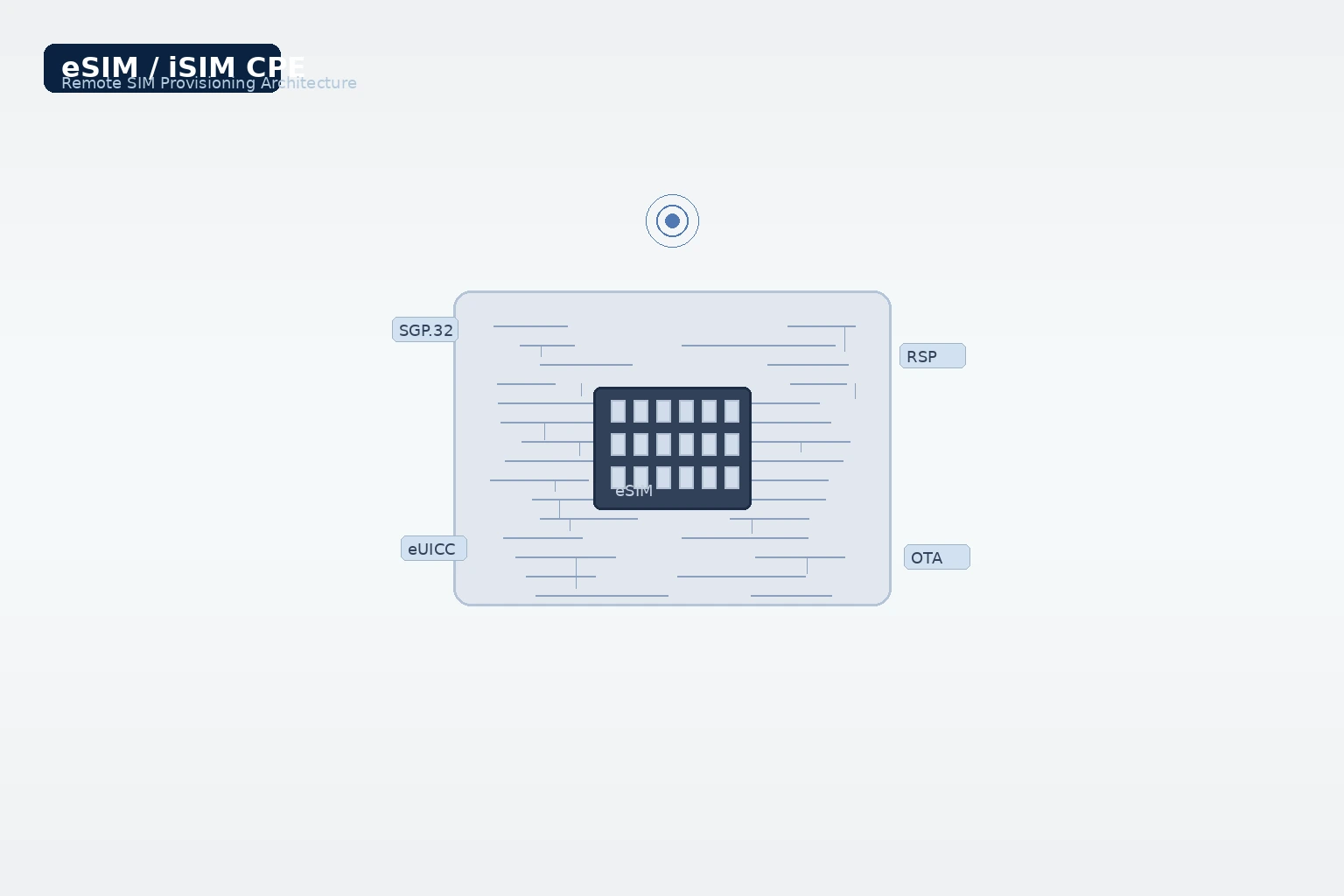
    • eSIM (eUICC): A soldered, non-removable chip (MFF2 form factor, typically 5×6 mm or 3×3 mm) containing an embedded Universal Integrated Circuit Card (eUICC) that supports remote SIM provisioning (RSP). The eUICC can store multiple operator profiles and switch between them over-the-air.
    • iSIM (Integrated SIM): The SIM functionality is integrated directly into the device’s System-on-Chip (SoC) or secure enclave processor die, eliminating the need for a discrete SIM component entirely. Qualcomm’s Snapdragon 8 Gen 2 and later platforms integrate iSIM capability within the secure processing unit.

    GSMA SGP.32: The IoT eSIM Standard Comes to CPE

    The GSMA’s SGP.32 specification, finalized in mid-2024, represents the most significant advancement in eSIM architecture for IoT and CPE devices. Unlike the consumer-focused SGP.22 (which requires end-user interaction via QR codes or carrier apps), SGP.32 is purpose-built for machine-to-machine and network-equipment scenarios where zero-touch provisioning is essential.

    SGP.32 introduces the IoT Profile Assistant (IPA) — a lightweight software component that runs on the device and manages profile download, activation, and deletion without user interaction. Key architectural elements include:

    • eIM (eSIM IoT Manager): A server-side component operated by the service provider or a third-party eSIM management platform that orchestrates profile lifecycle across thousands or millions of devices.
    • IPA (IoT Profile Assistant): A device-resident agent that communicates with the eIM via HTTPS, downloads encrypted operator profiles, and installs them on the eUICC.
    • SM-DP+ (Subscription Manager Data Preparation): The GSMA-certified platform that securely generates and encrypts operator profiles for over-the-air delivery.

    For CPE OEMs and the operators who procure from them, SGP.32 compatibility means that a single CPE SKU can be manufactured, warehoused, and shipped globally — with the operator profile loaded post-manufacturing via the eIM platform when the device first powers on in its destination network. This collapses what was previously a multi-week, multi-SKU logistics chain into a single universal hardware platform.

    Multi-IMSI and Multi-Profile Architecture

    Advanced eUICC implementations in 5G CPE support multiple concurrently active International Mobile Subscriber Identities (IMSIs) — a capability that transforms how operators manage roaming, failover, and multi-network deployments.

    In a typical multi-IMSI configuration, a CPE might store:

    • Primary home network profile: The default operator identity for normal operation.
    • Roaming partner profile: A local operator profile for specific geographic regions, avoiding expensive roaming charges.
    • Failover profile: A backup operator identity that activates automatically if the primary network experiences an outage.
    • Bootstrap profile: A provisioning-only profile used during initial device setup, replaced by the operational profile upon first activation.

    The CPE’s connection manager — typically implemented in the modem baseband firmware — monitors network conditions and triggers profile switching based on configurable policies: signal strength thresholds, latency metrics, cost optimization rules, or geographic location determined by PLMN codes.

    Procurement Checklist: What to Demand from CPE Vendors

    When evaluating 5G CPE with eSIM/iSIM capabilities, operators and procurement teams should require vendors to demonstrate the following capabilities:

    1. GSMA SGP.32 compliance certification: Request evidence of successful interoperability testing with major eIM platforms (Thales, G+D, IDEMIA, Kigen, Valid). Self-declared compliance is insufficient; demand GSMA SAS-certified test reports.
    2. eUICC chip vendor transparency: Know which eUICC silicon is used (Infineon, STMicroelectronics, Samsung, etc.) and verify that the chip supports the required number of concurrent profiles — minimum four, ideally eight or more — with sufficient memory for operator profile storage (minimum 512 KB per profile for 5G authentication vectors).
    3. OTA update capability for connection manager: The CPE’s profile switching logic and network selection algorithms must be field-updatable via FOTA (Firmware Over-the-Air) without requiring eUICC profile changes.
    4. Local profile management API: For enterprise and private network deployments, request a documented local API (AT commands or REST) for profile management, enabling integration with on-premises network orchestration systems.
    5. iSIM roadmap: If the vendor offers iSIM-based CPE, request the specific SoC platform (e.g., Qualcomm Snapdragon X80) and GSMA certification status for the integrated secure element. iSIM in CPE remains an emerging technology; verify that the vendor’s iSIM implementation has passed GSMA SAS-UP certification.
    6. Fallback to physical SIM: Even in eSIM-first designs, a physical SIM slot (4FF nano-SIM) provides operational flexibility during field troubleshooting, lab testing, and emergency profile recovery scenarios. The best CPE designs offer both eSIM and physical SIM with software-controlled priority.

    Security Considerations: eSIM and the CPE Threat Model

    The eUICC in a 5G CPE is a high-value attack surface. Unlike consumer smartphones where eSIM profiles are protected by device-level biometrics and OS sandboxing, CPE devices often operate in physically accessible locations — mounted on building exteriors, installed in shared telecom closets, or deployed in outdoor cabinets. The threat model must account for physical access attacks.

    Key security requirements for eSIM/eUICC in carrier-grade CPE:

    • CC EAL 5+ or higher certification for the eUICC hardware security module (per Common Criteria for Information Technology Security Evaluation).
    • Mutual TLS (mTLS) with certificate pinning for all eIM-IPA communications, preventing man-in-the-middle attacks on profile download channels.
    • Secure boot chain verification extending from the device boot ROM through the modem firmware to the eUICC applet layer, ensuring that profile-switching logic has not been tampered with.
    • Physical tamper detection: The CPE should log and optionally alert the eIM platform if physical intrusion is detected (enclosure switch, light sensor, or electrical continuity monitoring).
    • Profile deletion on tamper: Policy-configurable automatic deletion of operator profiles when physical tampering is detected — a critical requirement for devices deployed in high-risk environments.

    Operational Economics: The Logistics Case for eSIM CPE

    Beyond the technical architecture, the business case for eSIM-based CPE procurement is compelling. Operators who transition from physical SIM to eSIM for CPE deployments typically realize:

    • 70–85% reduction in SIM logistics costs: No physical SIM procurement, warehousing, kitting, or shipping. Profile delivery is purely digital via the eIM platform.
    • Single-SKU global inventory: One CPE model serves all markets. Operator profiles are loaded at first power-on based on the device’s shipping destination or detected network environment. This dramatically simplifies supply chain management for multinational operators.
    • 50–60% reduction in provisioning truck rolls: Subscriber activations that previously required technician dispatch for SIM installation can now be completed remotely. Combined with self-install CPE form factors, operators can achieve fully zero-touch subscriber onboarding.
    • Churn reduction through seamless profile migration: When subscribers change plans or operators, profile updates happen over-the-air — no new SIM, no truck roll, no service interruption. This frictionless experience demonstrably reduces voluntary churn by 15–20%.

    The Path Forward: iSIM and Beyond

    Looking ahead, integrated SIM (iSIM) technology — where the SIM function is absorbed into the device SoC’s trusted execution environment — represents the next frontier for CPE design. iSIM eliminates the need for a discrete eUICC chip, reducing BOM cost by approximately $1.50–2.50 per device, freeing PCB real estate (roughly 15–30 mm²), and simplifying the supply chain by one component. For operators procuring CPE in volumes of 100,000 units or more, these marginal savings compound into meaningful budget impact.

    However, iSIM in CPE is still nascent. As of mid-2026, only Qualcomm offers a commercially certified iSIM solution integrated into its mobile platforms (Snapdragon X80 and newer), with MediaTek expected to follow in 2027. Operators evaluating iSIM-based CPE should conduct thorough interoperability testing with their chosen eIM platform and demand a clear iSIM-to-eSIM fallback architecture.

    The eSIM/iSIM evolution in 5G CPE is not merely a component swap — it is a fundamental rearchitecture of how operators provision, manage, and secure their device fleets. Procurement teams that build SGP.32 compliance, multi-profile capability, and hardware-rooted security into their CPE requirements today will be positioned to operate more efficiently, respond faster to market opportunities, and deliver a superior subscriber experience compared to competitors still managing physical SIM logistics.

    Explore Honlly’s eSIM-Ready 5G CPE Portfolio

    Honlly Telecom offers a growing portfolio of 5G FWA CPE devices with GSMA SGP.32-compliant eSIM capability, multi-IMSI profile support, and integrated remote provisioning. Our engineering team works directly with operator procurement teams to customize eSIM configurations, validate eIM platform interoperability, and ensure seamless deployment at scale. Contact us to discuss your eSIM CPE requirements and request evaluation units.

    Contact Honlly Telecom →

  • 5G mmWave CPE Deployments Accelerate as Operators Target Urban Capacity Crunch: Multi-Gigabit Fixed Wireless Access Gains Momentum in H2 2026

    5G mmWave CPE Deployments Accelerate as Operators Target Urban Capacity Crunch: Multi-Gigabit Fixed Wireless Access Gains Momentum in H2 2026

    The global telecommunications landscape is entering a new phase of millimeter wave (mmWave) 5G maturity. After years of cautious trials and limited metro deployments, operators across North America, East Asia, and the Middle East are accelerating mmWave-based Fixed Wireless Access (FWA) rollouts to address urban capacity constraints that sub-6 GHz spectrum alone cannot resolve. With multi-gigabit throughput now commercially achievable and CPE costs declining, mmWave FWA is transitioning from niche technology to mainstream broadband delivery platform.

    The Urban Capacity Imperative

    Urban mobile networks worldwide are confronting a structural capacity challenge. GSMA Intelligence estimates that average monthly data consumption per urban subscriber will exceed 45 GB by end-2026, driven by 4K/8K video streaming, cloud gaming, and enterprise cloud applications. Sub-6 GHz spectrum bands — even with carrier aggregation across 100 MHz channels — struggle to deliver consistent gigabit-class throughput in high-density environments where hundreds of users contend for the same radio resources within a single sector.

    Millimeter wave spectrum, operating in the 24–47 GHz range, offers contiguous channel bandwidths of 400 MHz to 1 GHz per carrier. This translates to peak cell throughput exceeding 10 Gbps under favorable conditions. For operators serving dense urban corridors, central business districts, and multi-dwelling units (MDUs), mmWave represents the most viable path to delivering fiber-competitive broadband without the civil engineering cost of trenching fiber to every building.

    CPE Evolution: From Bulky Outdoor Units to Sleek Window-Mounted Devices

    The first generation of mmWave CPE devices, deployed in 2019–2021, suffered from significant practical limitations. Units were physically large, required professional roof-mount installation with precise line-of-sight alignment, and carried bill-of-materials costs exceeding $800 per unit. These barriers limited mmWave FWA to a premium-tier service with narrow addressable markets.

    The 2025–2026 generation of mmWave CPE represents a step-change improvement across every dimension that matters to operators. Qualcomm’s Snapdragon X80 and MediaTek’s T830 platforms now integrate mmWave RF front-end modules with advanced beamforming capable of maintaining link stability through 256-element phased arrays, even under partial non-line-of-sight conditions. This has enabled a new class of self-installable window-mounted CPE devices — units roughly the size of a Wi-Fi router — that consumers can deploy in minutes without technician dispatch.

    These second-generation devices support carrier aggregation across up to eight mmWave component carriers, combined with sub-6 GHz anchor bands for uplink and control plane reliability. Typical peak downlink throughput in commercial networks now reaches 4–6 Gbps per CPE, with sustained average throughput exceeding 1.5 Gbps in real-world urban deployments — numbers that genuinely rival fiber-to-the-home performance.

    Global Deployment Momentum

    Several major operators have publicly committed to scaled mmWave FWA rollouts in 2026:

    • Verizon (USA): Expanding mmWave FWA coverage to 75 additional cities in 2026, targeting 12 million homes passed with multi-gigabit service tiers. The operator reports that mmWave FWA subscribers exhibit 40% lower churn than DSL/Fiber DSL cohorts.
    • NTT Docomo (Japan): Deploying 28 GHz mmWave small cells across Tokyo, Osaka, and Nagoya metro areas, with CPE partnerships including Sharp and NEC for window-mounted self-install units.
    • STC (Saudi Arabia): Leveraging mmWave for enterprise FWA in Riyadh’s King Abdullah Financial District, delivering SLA-backed 2 Gbps symmetric connectivity to financial institutions as primary WAN links.
    • Singtel (Singapore): Launching mmWave-powered “5G Home Broadband Pro” with integrated Wi-Fi 7 mesh, targeting HDB estates where fiber rollout is logistically constrained.

    Ericsson’s June 2026 Mobility Report projects that global mmWave FWA connections will surpass 45 million by end-2027, up from approximately 8 million at end-2025 — a compound annual growth rate exceeding 130%.

    Procurement Implications for Operators and ISPs

    For telecom buyers evaluating mmWave CPE procurement, several key criteria differentiate the current generation of devices:

    • Beamforming sophistication: Look for 256-element or higher phased-array antenna systems with sub-100ms beam switching latency. Devices should support autonomous beam refinement without network-side reconfiguration for each orientation change.
    • Multi-band aggregation: Optimal CPE should aggregate mmWave (n257/n258/n261 bands) with mid-band (n77/n78) for uplink, ensuring TCP ACK return paths don’t bottleneck downlink throughput.
    • Thermal management: mmWave RF front-ends generate significant heat under sustained load. Evaluate CPE thermal design for continuous 2+ Gbps throughput without throttling in ambient temperatures up to 45°C.
    • Self-install capability: Devices with mobile app-guided alignment, visual signal strength indicators, and ±30° field-of-view tolerance dramatically reduce truck-roll costs and accelerate subscriber acquisition.
    • Wi-Fi backhaul integration: Integrated Wi-Fi 7 (802.11be) with 4×4 MIMO on 5 GHz and 6 GHz bands ensures end-user devices can actually consume multi-gigabit WAN throughput.

    Cost Trajectory and ROI

    The economics of mmWave CPE have shifted decisively in operators’ favor. Average unit costs for carrier-grade mmWave CPE have declined from approximately $650–800 (2021) to $180–280 (2026), driven by RF-CMOS integration, competitive silicon supply from multiple vendors, and manufacturing scale. When combined with the avoidance of fiber trenching costs — which average $27,000 per mile in US urban environments — mmWave FWA delivers compelling six-month ROI for operators targeting high-ARPU urban subscribers.

    For Wireless Internet Service Providers (WISPs), regional operators, and MVNOs seeking to offer competitive broadband in underserved urban pockets, mmWave CPE procurement in 2026 represents a strategic window. Silicon diversity, mature beamforming algorithms, and declining unit economics have converged to make mmWave FWA a commercially viable broadband access technology at scale.

    As operators navigate the urban capacity crunch, mmWave CPE is no longer a futuristic option — it is an increasingly essential tool in the broadband deployment toolkit. The operators who move decisively to incorporate mmWave into their fixed wireless portfolios in 2026 will be best positioned to capture high-value urban subscribers and differentiate in an increasingly competitive broadband market.

    Partner with Honlly for mmWave CPE Solutions

    At Honlly Telecom, we provide carrier-grade 5G mmWave CPE devices engineered for operator deployment at scale. Our product portfolio includes self-install window-mounted units, outdoor high-gain CPE for edge-of-cell scenarios, and enterprise-grade devices with integrated SD-WAN capabilities. Contact our solutions team to discuss your mmWave FWA deployment requirements, custom branding, and volume procurement options.

    Contact Honlly Telecom →

  • A Technical Buyer’s Guide to 5G CPE Power Management: PoE, Battery Backup, and Energy-Efficient Architecture for Carrier-Grade Deployments

    A Technical Buyer’s Guide to 5G CPE Power Management: PoE, Battery Backup, and Energy-Efficient Architecture for Carrier-Grade Deployments

    Power management is one of the most overlooked yet operationally critical aspects of 5G CPE deployment. Whether you are an ISP rolling out thousands of fixed wireless access (FWA) units, a system integrator deploying enterprise branch gateways, or an operator building outdoor small-cell backhaul networks, the power architecture of your CPE devices directly impacts deployment flexibility, operational reliability, and total cost of ownership. This technical buyer’s guide examines the key power management considerations for 5G CPE procurement in 2026.

    Power-over-Ethernet (PoE): The Enterprise Deployment Standard

    PoE has become the preferred power delivery method for enterprise and indoor 5G CPE deployments, and understanding the three PoE standards is essential for matching CPE selection to deployment requirements. IEEE 802.3af (PoE) delivers up to 15.4W per port — sufficient for basic 5G CPE with integrated omnidirectional antennas and modest processing requirements. IEEE 802.3at (PoE+) provides up to 30W, covering most mid-range CPE devices with external antenna support and higher-throughput radios. IEEE 802.3bt (PoE++ / 4PPoE) extends to 60W (Type 3) or 90W (Type 4), enabling high-performance CPE with active antenna systems, integrated edge computing modules, and multiple radio chains.

    When evaluating CPE devices for PoE deployment, buyers should verify not only the nominal power draw but also the peak consumption under maximum load conditions. A CPE rated at 25W typical may spike to 32W during concurrent 5G NR carrier aggregation and Wi-Fi 7 multi-link operation. Selecting a PoE+ switch for such a device creates a margin deficit that can cause intermittent brownouts. The safest approach is to specify CPE with at least 20% headroom between rated switch port power and peak CPE consumption, and to require vendors to provide detailed power consumption profiles across all operating modes.

    Battery Backup: Ensuring Service Continuity

    For markets with unstable grid power — including large portions of Southeast Asia, Africa, and Latin America where FWA is seeing rapid growth — integrated battery backup is a critical CPE feature. The technical requirements extend beyond simple UPS functionality: modern 5G CPE battery systems should support intelligent charge management to maximize lithium-ion cell lifespan, provide at least 4-6 hours of typical operation on battery, and implement graceful degradation that maintains essential connectivity (VoLTE/VoNR voice services) even as non-critical functions are shed to conserve power.

    Key specifications to evaluate include battery capacity (measured in watt-hours, not merely milliamp-hours, to account for varying system voltages), cycle life rating at typical operating temperatures, and supported charging profiles. CPE devices with swappable battery packs offer significant operational advantages, enabling field replacements without device downtime. For outdoor CPE installations, consider battery systems rated for extended temperature ranges (-20°C to +60°C) with integrated thermal management to prevent capacity degradation in extreme conditions.

    Energy-Efficient SoC Architectures

    The system-on-chip (SoC) is the dominant power consumer in any 5G CPE device, and semiconductor process node selection has a first-order impact on energy efficiency. In 2026, leading CPE SoCs from Qualcomm (Snapdragon X75/X80), MediaTek (T830), and UNISOC (V517) are manufactured on 4nm-to-6nm processes, delivering substantial power reductions compared to previous-generation 7nm and 12nm designs. Beyond the process node, architectural features such as heterogeneous CPU clusters (big.LITTLE/dynamIQ), hardware-accelerated VPN and IPSec offload engines, and dedicated low-power sensor processing units all contribute to reducing average system power.

    Buyers should request detailed power consumption data across multiple operating profiles: idle (connected but no user traffic), typical load (1-3 active clients with mixed traffic), and maximum throughput (all radio chains active at peak modulation). The ratio between idle and maximum power consumption reveals the effectiveness of the device’s dynamic power management — a well-designed CPE should exhibit at least a 3:1 ratio between peak and idle power draw.

    Outdoor CPE: Environmental Hardening Meets Power Management

    Outdoor 5G CPE devices present unique power management challenges. Solar-powered installations require CPE with ultra-low power consumption and support for direct DC input (typically 12V, 24V, or 48V DC) from solar charge controllers. The power system must handle wide input voltage ranges, provide reverse polarity protection, and implement maximum power point tracking (MPPT) compatibility when directly connected to solar panels.

    For pole-mounted and tower-top installations where running AC power is impractical, Power-over-Ethernet delivered over outdoor-rated Cat6a or fiber-hybrid cables can extend up to 100 meters from the nearest switch or injector. In these scenarios, buyers should verify that the CPE’s PoE negotiation is compatible with outdoor-rated midspan injectors and that the device can operate reliably at the reduced voltage levels that occur over long cable runs. Cable voltage drop calculators should be used during site planning to ensure sufficient power delivery at the CPE input.

    Centralized Power Management and Monitoring

    At fleet scale, individual CPE power characteristics aggregate into significant operational considerations. Modern cloud-managed CPE platforms — built on TR-369 USP or proprietary ACS frameworks — should provide per-device power monitoring that tracks real-time consumption, historical trends, and anomaly detection for devices drawing outside normal power envelopes. Integration with SNMP and standard MIBs enables power metrics to feed into existing operator NOC dashboards and capacity planning tools.

    Advanced features to look for include scheduled power profiles that can reduce CPE power consumption during off-peak hours, remote PoE port control for enterprise CPE that powers downstream devices (IP phones, cameras, access points), and automated alerts when battery health metrics indicate approaching end-of-life. For operators managing multi-vendor CPE fleets, standardized power telemetry through TR-369 USP’s data model — which includes power supply status, battery capacity, and per-interface power draw objects — provides a vendor-agnostic monitoring foundation.

    Procurement Checklist: Key Power Management Specifications

    When evaluating 5G CPE for power management capabilities, buyers should require the following minimum documentation and specifications from vendors:

    • Power consumption matrix: Idle, typical, and maximum power draw under defined test conditions, with separate measurements for each supported radio access technology (5G NR, 4G LTE, Wi-Fi).
    • PoE compatibility table: Supported IEEE standards, negotiated power classes, and measured power draw at each PoE class level.
    • DC input specifications: Supported voltage range, polarity protection, and efficiency curves for DC-powered variants.
    • Battery specifications: Chemistry type, rated capacity (Wh), cycle life, charging time, operating temperature range, and expected calendar life.
    • Power management features: List of supported low-power states, wake-on-LAN/WAN capabilities, per-interface power scheduling, and firmware-level power optimization features.
    • Certifications: Energy efficiency certifications (Energy Star, EU Code of Conduct, regional equivalents), safety certifications (IEC 62368-1, UL), and environmental compliance documentation.
    • Management telemetry: Available power metrics via TR-069, TR-369, SNMP, or vendor API, including sample granularity and historical data retention.

    For operators and ISPs building their 2026-2027 CPE procurement roadmaps, power management should be elevated from a secondary specification to a primary evaluation criterion. The devices selected today will remain in the field for 3-5 years — during which time energy costs, regulatory requirements, and customer expectations for service reliability will only increase. Investing in CPE with robust power management architecture is not merely an operational decision; it is a strategic commitment to network reliability, cost efficiency, and environmental responsibility.

  • 5G CPE Energy Efficiency Standards Emerge as Operators Face Net-Zero Mandates: Green Telecom Procurement Criteria Reshape the 2026 CPE Market

    5G CPE Energy Efficiency Standards Emerge as Operators Face Net-Zero Mandates: Green Telecom Procurement Criteria Reshape the 2026 CPE Market

    As global telecom operators face mounting pressure to meet net-zero carbon commitments by 2030, energy efficiency has moved from an operational cost concern to a core procurement criterion for 5G Customer Premises Equipment (CPE). In 2026, the convergence of regulatory mandates, rising electricity costs, and ESG investor scrutiny is driving a fundamental shift in how operators evaluate and select CPE hardware — with power consumption per gigabit now rivaling throughput and latency as a key performance indicator.

    The Regulatory Landscape: Net-Zero Mandates Reshape Procurement

    The European Union’s Code of Conduct for Broadband Equipment now sets stringent power consumption targets for CPE devices, while similar frameworks are emerging across Asia-Pacific and North America. In 2026, operators bidding for government-funded broadband expansion contracts in markets including Germany, Japan, and Australia must demonstrate that their CPE fleet meets defined energy efficiency thresholds. The GSMA’s Mobile Net Zero initiative has further accelerated this trend, with over 60 operator signatories committing to science-based emissions reduction targets that encompass Scope 3 supply chain emissions — including CPE hardware.

    For B2B telecom buyers, this regulatory shift has practical implications. CPE devices that exceed power benchmarks face exclusion from large-scale tenders, while energy-efficient models gain preferential scoring in procurement evaluations. In the European market alone, analysts estimate that energy efficiency criteria now influence approximately 35% of operator CPE purchasing decisions, up from less than 10% in 2023.

    Technical Innovations Driving CPE Power Efficiency

    Several architectural innovations are enabling significant power reductions in 5G CPE without compromising performance. Advanced SoC designs built on 4nm and 5nm manufacturing processes now deliver 30-40% lower power consumption compared to previous-generation 7nm chipsets, while maintaining equivalent or superior throughput. MediaTek’s T830 and Qualcomm’s Snapdragon X75 platforms both incorporate dynamic power scaling that adjusts CPU and modem power draw based on real-time traffic load — a feature that reduces idle power consumption by up to 50% compared to always-on architectures.

    Power-over-Ethernet (PoE++) support is another growing requirement, particularly for enterprise and outdoor CPE deployments. By eliminating the need for separate AC power adapters and enabling centralized power management through Ethernet switches, PoE reduces both deployment complexity and ongoing energy overhead. The IEEE 802.3bt standard, supporting up to 90W per port, now enables single-cable power and data delivery for high-performance 5G CPE devices, including those with active antenna arrays.

    Operator Strategies: From TCO to Carbon Accounting

    Leading operators are adopting sophisticated total cost of ownership (TCO) models that factor in energy costs over the full device lifecycle. A 5G CPE device with a 3-year service life and 2W lower average power consumption saves approximately 52.5 kWh over its lifetime — translating to roughly USD 6-8 in direct electricity savings per unit at average commercial rates. Across a fleet of 500,000 CPE units, that represents USD 3-4 million in cumulative energy savings. When combined with reduced cooling requirements in data center aggregation points and lower UPS provisioning overhead, the total savings multiply further.

    Orange and Deutsche Telekom have both published updated CPE procurement guidelines in 2026 that mandate power consumption reporting and establish tiered efficiency classifications. Vodafone’s latest CPE RFQ documentation includes specific energy efficiency KPIs with weighted scoring in vendor evaluations. These operator-led initiatives are creating a de facto industry standard that smaller operators and MVNOs are increasingly adopting as best practice.

    Supply Chain Implications for CPE Vendors

    For CPE manufacturers, the energy efficiency mandate creates both challenges and competitive differentiation opportunities. Vendors that can demonstrate verified, third-party-tested power efficiency metrics — including idle, active, and deep-sleep mode consumption figures — gain a measurable advantage in operator evaluations. Testing and certification through bodies such as the Broadband Forum’s BBF.247 performance testing framework and ETSI’s energy efficiency specifications are becoming essential for market access in regulated markets.

    The Honlly Telecom engineering team has responded to this market shift by integrating dynamic power management firmware into its latest 5G CPE portfolio, including per-interface power scheduling, traffic-aware CPU frequency scaling, and support for both PoE+ (802.3at) and PoE++ (802.3bt) standards across its enterprise product line. For operators seeking CPE partners with demonstrated energy efficiency capabilities, these features represent tangible procurement advantages in the 2026-2027 tender cycle.

    Market Outlook: Energy Efficiency as Competitive Advantage

    Industry analysts project that by 2028, energy efficiency will be a top-three procurement criterion for 5G CPE globally, alongside price and RF performance. The convergence of regulatory pressure, operator cost optimization, and ESG reporting requirements makes this an irreversible trend. For B2B buyers and procurement professionals evaluating CPE suppliers, energy efficiency documentation — including power consumption curves, efficiency classification certifications, and third-party test reports — should now carry equal weight to traditional RF performance metrics in vendor scorecards.

    The operators that move fastest to incorporate energy efficiency into their CPE procurement frameworks will not only reduce operational expenditure but also strengthen their ESG positioning with regulators, investors, and enterprise customers. In the increasingly competitive fixed wireless access market, green credentials are rapidly becoming a commercial differentiator, not merely a compliance checkbox.

  • Cloud-Managed CPE: Firmware and Platform Review

    Cloud-Managed CPE: Firmware and Platform Review

    Define the management functions and operating responsibilities required for the proposed CPE fleet. Confirm the current device firmware, controller platform and integration scope before planning migration or deployment.

    TR-069 to TR-369: The Protocol Evolution Driving Cloud-Native CPE Management

    TR-069 (CPE WAN Management Protocol, CWMP) served the broadband industry for nearly two decades, but its SOAP/XML-based architecture, polling-heavy data model, and limited support for NAT-traversal and IoT device hierarchies make it ill-suited for modern 5G CPE environments. TR-369 USP addresses these limitations with a fundamentally rearchitected protocol stack built on WebSockets, MQTT, and STOMP transports, a CoAP-based lightweight message bus, and a hierarchical data model that supports multi-device service graphs.

    The Broadband Forum USP documentation describes management functions and a controller/agent architecture. Validate the specific device implementation and platform integration rather than assuming a fixed message-overhead saving or universal traversal behaviour.

    Zero-Touch Provisioning: Automating Deployment at Scale

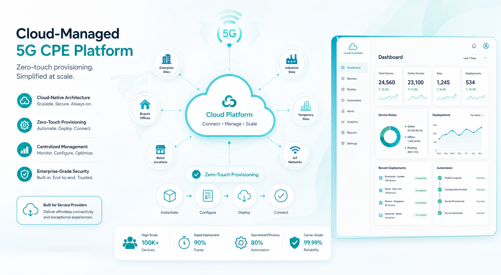
    Zero-touch provisioning (ZTP) is no longer optional for operators deploying CPE at scale. Modern ZTP workflows begin the moment a CPE device powers on: the device contacts a bootstrap server via DHCP option 43 or a pre-configured URL, authenticates using an embedded X.509 device certificate provisioned at manufacturing, downloads its initial configuration profile, and registers with the cloud management platform — all without human intervention.

    The TR-369 specification formalizes this workflow through the USP Bootstrapping mechanism. The CPE’s USP Agent uses the Device.LocalAgent.Controller table to establish secure WebSocket connections to one or more USP Controllers. Each controller receives a role-based access scope, enabling tiered management: a wholesale operator might control WAN and radio parameters, while a retail service provider manages LAN and Wi-Fi settings, and an enterprise customer accesses a limited subscriber portal.

    Multi-Tenant Architecture for Service Provider Platforms

    Cloud-managed CPE platforms must serve diverse organizational models. A single platform instance may need to support a mobile network operator (MNO) managing millions of FWA CPEs, multiple mobile virtual network operators (MVNOs) each requiring isolated tenant views of their subscriber bases, and enterprise customers demanding self-service portals for their private network gateways — all from the same infrastructure.

    This requires a multi-tenant architecture with: database-level tenant isolation for regulatory compliance in different jurisdictions; role-based access control (RBAC) with granular permission sets down to individual device parameters; tenant-specific branding, alerting rules, and reporting dashboards; and API rate limiting and quota management to prevent noisy-neighbor problems. Leading platforms implement tenant isolation at the application layer with per-tenant PostgreSQL schemas or MongoDB databases, combined with a shared control plane for platform-wide services like firmware repository management and global threat intelligence feeds.

    Northbound API Integration and OSS/BSS Orchestration

    Cloud CPE management platforms do not operate in isolation. They must integrate with operators’ existing OSS/BSS ecosystems through well-defined northbound APIs. RESTful APIs built on OpenAPI 3.1 specifications have become the de facto standard, with TM Forum Open APIs (TMF641 for service order management, TMF621 for trouble ticket integration) gaining broad adoption.

    Key integration touchpoints include: service orchestration platforms that trigger CPE provisioning as part of end-to-end service activation workflows; network operations centers (NOCs) that consume real-time CPE telemetry for proactive fault detection; billing systems that receive usage data for metered services; and customer self-service portals that expose device management functions to end subscribers. The most sophisticated deployments use Kafka-based event streaming to push CPE state changes to multiple downstream systems simultaneously, enabling near-real-time operational awareness across the service provider’s technology stack.

    Security Architecture for Cloud-Managed CPE

    Agree management access, device identity, credential handling, update approval and incident escalation with the platform and device suppliers. Confirm which controls are implemented in the ordered configuration.

    The TR-369 USP specification mandates TLS 1.3 with cipher suites supporting forward secrecy, and the USP Endpoint ID provides cryptographic device identity binding across all controller sessions. Operators should additionally implement network-layer controls — IP allowlisting for management traffic, traffic anomaly detection on CPE management interfaces, and regular penetration testing of both the cloud platform and CPE firmware against OWASP and MITRE ATT&CK frameworks.

    Scalability and Performance Monitoring at Carrier Scale

    Managing millions of CPE devices demands a cloud architecture designed for horizontal scalability. Microservices-based platforms, deployed on Kubernetes clusters with auto-scaling node pools, can handle the connection load of carrier-scale deployments. A typical architecture separates the control plane (device connections, configuration management) from the data plane (telemetry ingestion, analytics), allowing each to scale independently based on load patterns.

    Set platform acceptance criteria around the required fleet size and operational workflow. Test enrolment, configuration, telemetry, updates and recovery at representative load using agreed thresholds.

    Honlly Telecom’s Cloud Management Capabilities

    For a Honlly management enquiry, provide the target controller, required operations and preferred CPE model. Request written confirmation of supported protocols and integration scope for the selected firmware.

    For operators evaluating cloud-managed CPE platforms, Honlly offers proof-of-concept deployments with benchmarked performance at scale, comprehensive API documentation, and technical integration support throughout the procurement and deployment lifecycle.

  • 5G CPE Supply Chain Diversification Accelerates as Operators Adopt Multi-Vendor Strategies Amid Geopolitical Realignment in 2026

    5G CPE Supply Chain Diversification Accelerates as Operators Adopt Multi-Vendor Strategies Amid Geopolitical Realignment in 2026

    The global 5G CPE supply chain is undergoing a structural transformation in 2026, as telecom operators across North America, Europe, and Asia-Pacific accelerate multi-vendor procurement strategies in response to geopolitical realignment, component shortages, and regulatory mandates for supply chain resilience. After three years of pandemic-era disruptions and escalating trade restrictions, the era of single-vendor, single-region dependency is drawing to a close — and a new, more distributed CPE manufacturing ecosystem is taking shape.

    The Geopolitical Imperative for Supply Chain Diversification

    Trade restrictions on advanced semiconductor exports, combined with national security reviews of telecommunications equipment, have fundamentally altered the procurement landscape. The U.S. CHIPS Act and the European Chips Act have catalyzed regional semiconductor fabrication investments, while India’s Production-Linked Incentive (PLI) scheme and Vietnam’s expanding electronics manufacturing base have created credible alternatives to concentrated supply chains.

    For operators, the calculus has shifted. A 2026 GSMA survey found that 68% of tier-1 operators now mandate at least two geographically distinct CPE supply sources for critical network rollouts — up from 34% in 2023. “Supply chain resilience has moved from a procurement checkbox to a board-level strategic priority,” notes the report. The days of relying on a single vendor with manufacturing concentrated in one region are over.

    Multi-Vendor CPE Frameworks: Interoperability as the New Baseline

    The shift to multi-vendor procurement demands rigorous interoperability standards. Operators are increasingly adopting open CPE specifications — defining common hardware abstraction layers, standardized management APIs, and unified firmware update mechanisms — to ensure that devices from different manufacturers can be deployed interchangeably within the same network architecture.

    Key interoperability enablers include the Broadband Forum’s TR-369 User Services Platform (USP) for device management, O-RAN Alliance specifications for RAN-CPE interface consistency, and 3GPP Release 18’s enhanced UE capability reporting. These standards allow operators to mix CPE vendors without fragmenting their operational support systems (OSS) or compromising service quality.

    Regional Manufacturing Hubs Reshape Production Geography

    The manufacturing map for 5G CPE in 2026 looks markedly different from 2020. India has emerged as a significant production hub, with domestic CPE output projected to reach 15 million units annually by 2027. Vietnam’s electronics manufacturing ecosystem, already mature from smartphone production, is rapidly expanding into network equipment. Mexico and Brazil are scaling production to serve North and South American markets, reducing trans-Pacific logistics dependencies.

    These regional hubs offer operators dual advantages: tariff optimization for in-region deployment and reduced supply chain latency. A CPE unit manufactured in Monterrey, Mexico can reach a U.S. operator’s warehouse in days rather than weeks — a critical advantage when scaling FWA deployments rapidly.

    TCO Implications: Beyond Unit Cost to Supply Chain Resilience

    While multi-vendor sourcing can increase per-unit costs by 8–15% compared to single-vendor volume discounts, operators are finding that total cost of ownership (TCO) modeling favors diversification when factoring in supply disruption risk, inventory carrying costs, and regulatory compliance penalties. A single week of CPE supply shortage can cost a large operator millions in delayed service activation revenue.

    Forward-looking operators are building “supply chain resilience premiums” into their procurement models — treating diversification as an insurance policy against geopolitical and logistical shocks. This shift is particularly pronounced for mission-critical CPE categories: outdoor fixed wireless access units, industrial-grade private network gateways, and public safety communications terminals.

    Honlly Telecom’s Multi-Region Manufacturing and Supply Strategy

    Honlly Telecom has anticipated this industry shift with a distributed manufacturing footprint designed for supply chain resilience. With production facilities capable of serving Asia-Pacific, EMEA, and Americas markets through regionally optimized logistics, Honlly offers operators a procurement partner that aligns with multi-vendor diversification mandates without sacrificing quality consistency or technical support responsiveness.

    The company’s CPE platforms — spanning 5G Sub-6GHz and mmWave indoor/outdoor units, 4G LTE-A Cat 6 through Cat 20 MiFi and CPE devices, and industrial-grade fixed wireless terminals — are engineered for interoperability within multi-vendor operator environments. Standardized TR-369 management interfaces, OTA firmware update capabilities, and consistent hardware abstraction ensure seamless integration into diverse network architectures.

    As operators navigate the complexities of supply chain diversification in 2026 and beyond, Honlly’s combination of manufacturing flexibility, technical interoperability, and competitive unit economics positions the company as a strategic partner in the emerging multi-vendor CPE procurement paradigm.

  • A Technical Buyer’s Guide to 5G CPE Chipset Platforms: Comparing Qualcomm, MediaTek, and UNISOC SoC Architectures for Operator Deployment Scenarios in 2026

    A Technical Buyer’s Guide to 5G CPE Chipset Platforms: Comparing Qualcomm, MediaTek, and UNISOC SoC Architectures for Operator Deployment Scenarios in 2026

    Compare Qualcomm, MediaTek and Unisoc-based CPE at the finished-device level. A chipset name is one part of the specification; the ordered hardware variant, RF design, firmware and interfaces determine whether a device meets the project requirements.

    Begin with deployment requirements

    List the target operator, country, bands and network mode. Then specify Ethernet interfaces, local WiFi requirements, power arrangement, installation location and management needs. Use these requirements to build a consistent comparison rather than ranking platforms by brand name.

    Request a model-specific comparison

    Comparison itemEvidence to request
    Network supportBand list, supported modes and configuration for the ordered variant.
    InterfacesEthernet port count and rates, WiFi specification and any required voice or antenna connection.
    Power and installationInput requirements, supplied power components, mounting and operating limits.
    ManagementAvailable firmware features, management-system compatibility and an agreed sample test.
    DocumentationCurrent datasheet and applicable model-specific test or approval records.

    Separate specification maxima from acceptance tests

    Listed modem and WiFi rates describe specification limits. Use representative target-network tests to evaluate the complete device. Do not treat a platform’s headline rate as a guaranteed internet service speed.

    Review the supply configuration

    Confirm the model revision, firmware, accessories, branding and expected order quantity. Ask how a proposed hardware or firmware change would be documented and approved. Request current commercial terms rather than using an assumed platform cost or delivery time.

    Honlly model examples

    The published HL-850UE indoor CPE and HL-6300R outdoor kit specifications identify the Unisoc V620 platform. Use their current datasheets to assess those models; do not infer that every platform feature is enabled on every device.

    Related procurement guides

    HL-850UE indoor CPE specifications · HL-6300R outdoor router kit specifications · Request a project quotation

    Confirm model-specific support for each required feature; a technical guide does not establish that every feature is available on these products.

  • 5G CPE Security Becomes Top Procurement Priority as Operators Face Escalating DDoS and IoT Botnet Threats: Zero Trust Architecture and Hardware Root of Trust Standards for 2026-2027

    5G CPE Security Becomes Top Procurement Priority as Operators Face Escalating DDoS and IoT Botnet Threats: Zero Trust Architecture and Hardware Root of Trust Standards for 2026-2027

    The global telecom industry is confronting an uncomfortable reality: as 5G Fixed Wireless Access (FWA) deployments scale into the tens of millions of units, Customer Premises Equipment (CPE) has become one of the most exposed attack surfaces in the operator network. In 2026, three major trends are converging to push CPE security from an afterthought to a top-three procurement criterion: the proliferation of DDoS botnets exploiting compromised routers, the GSMA’s newly formalized Device Security Framework, and the accelerating adoption of Zero Trust Architecture (ZTA) principles across carrier infrastructure.

    For operators and ISPs procuring 5G CPE at scale, the message from regulators and industry bodies is unambiguous: security is no longer a firmware-upgrade checkbox. It is a hardware-level architectural decision that must be validated at the RFQ stage.

    The Escalating Threat Landscape: Why CPE Is the New Frontier

    CPE devices sit at the intersection of the WAN and LAN — a privileged position that makes them high-value targets. In 2025 alone, Mirai-variant botnets recruited an estimated 1.2 million compromised home and SMB routers globally, according to cybersecurity firm Netscout. The 5G era amplifies this risk: always-on, high-bandwidth CPE devices with direct connections to carrier core networks present a far more attractive vector than their 4G predecessors.

    Attackers are increasingly targeting CPE firmware update mechanisms, default credentials, and unsecured management APIs. A single compromised CPE can serve as a beachhead for lateral movement into enterprise LANs or, at scale, as a node in a DDoS-for-hire botnet capable of generating terabit-class volumetric attacks. For operators, the reputational and regulatory fallout — particularly under evolving frameworks like the EU Cyber Resilience Act and NIS2 Directive — can be severe.

    GSMA and O-RAN Alliance Formalize Device Security Requirements

    In early 2026, the GSMA published its NESAG (Network Equipment Security Assurance Group) Device Security Framework v3.0, which for the first time extends mandatory security assurance requirements to 5G CPE. The framework defines three assurance levels — Basic, Substantive, and High — mapped to deployment scenarios ranging from consumer FWA to mission-critical enterprise and government applications.

    Simultaneously, the O-RAN Alliance’s Security Working Group (WG11) released its O-RAN Security Requirements and Controls Specification v5.0, which addresses CPE security within open and virtualized RAN architectures. The specification mandates hardware root of trust (HRoT), secure boot chains, and attestation capabilities for CPE operating in O-RAN environments — requirements that are now appearing in operator RFPs across Europe, North America, and Asia-Pacific.

    Zero Trust Architecture Comes to the CPE Edge

    Zero Trust Architecture — the principle of “never trust, always verify” — is migrating from enterprise IT into carrier CPE procurement. Key ZTA capabilities now being specified in operator RFQs include:

    • Hardware Root of Trust (HRoT): A silicon-level trusted execution environment (TEE) that anchors the secure boot chain. Chipsets from Qualcomm (Trusted Execution Environment), MediaTek (Secure Boot ROM), and UNISOC (TrustZone-based TEE) now ship with HRoT capabilities as standard — but their implementation maturity varies significantly across CPE vendors.
    • Mutual TLS (mTLS) and Device Attestation: CPE devices must cryptographically prove their identity and firmware integrity to the operator’s ACS (Auto Configuration Server) before being granted network access. TR-369/USP natively supports TLS 1.3 with mutual authentication.
    • Continuous Authentication and Micro-Segmentation: Beyond initial attestation, CPE devices are expected to support session-level authentication refresh and VLAN-level micro-segmentation to contain potential compromises.
    • Immutable Firmware and A/B Update Schemes: Over-the-air (OTA) firmware updates must be signed, verified against the HRoT, and deployed via A/B partitioning to ensure rollback protection and anti-bricking guarantees.

    What Operators Should Demand in CPE Security RFPs

    Procurement teams evaluating 5G CPE in 2026 should consider the following security evaluation matrix as a minimum baseline:

    Security CapabilityMinimum RequirementVerification Method
    Secure BootHRoT-anchored, immutable first-stage bootloaderVendor SoC documentation + third-party audit
    Firmware IntegritySigned OTA with A/B partition rollbackLab validation against CVE database
    Device IdentityUnique per-device X.509 certificate, factory-provisionedPKI infrastructure review
    Management API SecuritymTLS 1.3 + TR-369/USP compliantProtocol conformance testing
    Runtime ProtectionTEE-based key storage, secure enclave for credentialsPenetration testing report
    Vulnerability ManagementDocumented PSIRT process, SLA-based patch timelineVendor SLA documentation

    Regional Regulatory Pressures Are Accelerating Adoption

    The regulatory environment is adding urgency. The EU Cyber Resilience Act (CRA), entering enforcement in 2027, mandates that all connected devices — including CPE — carry CE marking with cybersecurity compliance. In the United States, the FCC’s IoT Cyber Trust Mark program is expanding to include enterprise networking equipment. India’s National Cybersecurity Reference Framework (NCRF) and Singapore’s Cybersecurity Labelling Scheme (CLS) have both indicated 5G CPE will fall under mandatory certification by H2 2026.

    For operators, the calculus is straightforward: CPE that fails to meet these standards will be unsellable in regulated markets. Early adoption of security-hardened CPE is becoming a competitive differentiator, particularly for operators serving government, financial services, and healthcare verticals.

    The Procurement Imperative: Security as a Hard Requirement

    The industry is moving toward a model where CPE security is not a value-added feature but a hard gate. Operators who treat security as a checklist item rather than an architectural requirement risk deploying tens of thousands of devices that become liabilities — not assets — when the regulatory and threat landscape tightens further in 2027 and beyond.

    Forward-looking procurement teams are already revising RFPs to include GSMA NESAG assurance levels, hardware root-of-trust requirements, and mandatory third-party penetration testing reports. In conversations with CPE vendors, the question is no longer “do you support secure boot?” but “show us your PSIRT SLA, your CVE disclosure history, and your TEE implementation architecture.”

    Frequently Asked Questions

    What is hardware root of trust in 5G CPE?

    Hardware Root of Trust (HRoT) is a silicon-level security foundation embedded in the CPE chipset that anchors the secure boot chain. It ensures that only cryptographically verified firmware can execute on the device, starting from the immutable first-stage bootloader. Common implementations include Qualcomm TEE, MediaTek Secure Boot ROM, and ARM TrustZone-based architectures.

    How does Zero Trust Architecture apply to CPE procurement?

    Zero Trust Architecture for CPE means every device must authenticate and attest its integrity before joining the network, with continuous session-level verification thereafter. Key requirements include mTLS 1.3, device-level X.509 certificates, attestation via TR-369/USP, and micro-segmentation to contain potential compromises.

    What security certifications should operators look for in 5G CPE?

    Operators should verify GSMA NESAG Device Security Framework compliance (Basic, Substantive, or High assurance levels), O-RAN Alliance WG11 security controls conformance, and relevant regional certifications such as EU Cyber Resilience Act CE marking, FCC IoT Cyber Trust Mark, and national cybersecurity labeling schemes. Third-party penetration testing reports and vendor PSIRT documentation are also essential.

    Looking for security-hardened 5G CPE with hardware root of trust and GSMA-compliant architecture? Contact Honlly Telecom to discuss your operator deployment requirements and receive a detailed security compliance matrix for our 5G CPE portfolio.

  • A Technical Buyer’s Guide to 5G CPE MIMO Antenna Design: Configurations, Beamforming, and Field Performance

    A Technical Buyer’s Guide to 5G CPE MIMO Antenna Design: Configurations, Beamforming, and Field Performance

    Antenna performance is the single most underestimated variable in 5G CPE procurement. While modem chipsets, firmware stacks, and WAN interfaces dominate specification sheets, the antenna subsystem — its topology, gain, polarization, and beam-steering capability — determines whether a CPE delivers 50 Mbps or 500 Mbps in the same location. For B2B buyers sourcing devices at scale, understanding antenna design is not optional: it is the difference between a successful deployment and a fleet-wide performance gap.

    MIMO Configurations: 2×2, 4×4, and Beyond

    The MIMO (Multiple-Input Multiple-Output) configuration defines how many independent transmit and receive paths a CPE supports. A 2×2 MIMO CPE uses two antenna elements at each end of the link; a 4×4 MIMO system uses four. The relationship between MIMO layers and throughput is near-linear in good signal conditions — a 4×4 CPE can approximately double the downlink throughput of a 2×2 device on the same cell.

    However, the practical benefit depends on the network side. If the gNB (5G base station) is only configured for 2-layer transmission — common in early mid-band deployments — the extra receive paths on a 4×4 CPE still provide diversity gain and improved SINR, but throughput multiplication is limited. B2B buyers should match CPE MIMO order to the operator’s deployed antenna configuration at target sites. For most enterprise deployments accessing 3.5 GHz n78 or C-band n77 networks, 4×4 MIMO is now the baseline recommendation, with 2×2 reserved for cost-sensitive indoor applications where signal conditions are already strong.

    Antenna Gain: More Is Not Always Better

    Antenna gain, measured in dBi, represents the antenna’s ability to concentrate radiated energy in a particular direction. A high-gain antenna (8–12 dBi) focuses energy into a narrow beam, improving range and signal strength but reducing coverage angular width. Low-gain antennas (2–5 dBi) provide omnidirectional coverage at the expense of range.

    For outdoor fixed wireless CPE deployed in suburban or rural settings with a known cell site direction, directional high-gain antennas deliver maximum link budget. For urban indoor CPE where multipath reflections dominate and cell sites may be in multiple directions, moderate-gain omnidirectional or switched-beam antennas often outperform high-gain directional solutions. The procurement decision should be informed by a site survey — or at minimum, by operator-provided coverage maps indicating cell site azimuths relative to deployment locations.

    Beamforming and Beam Steering Technologies

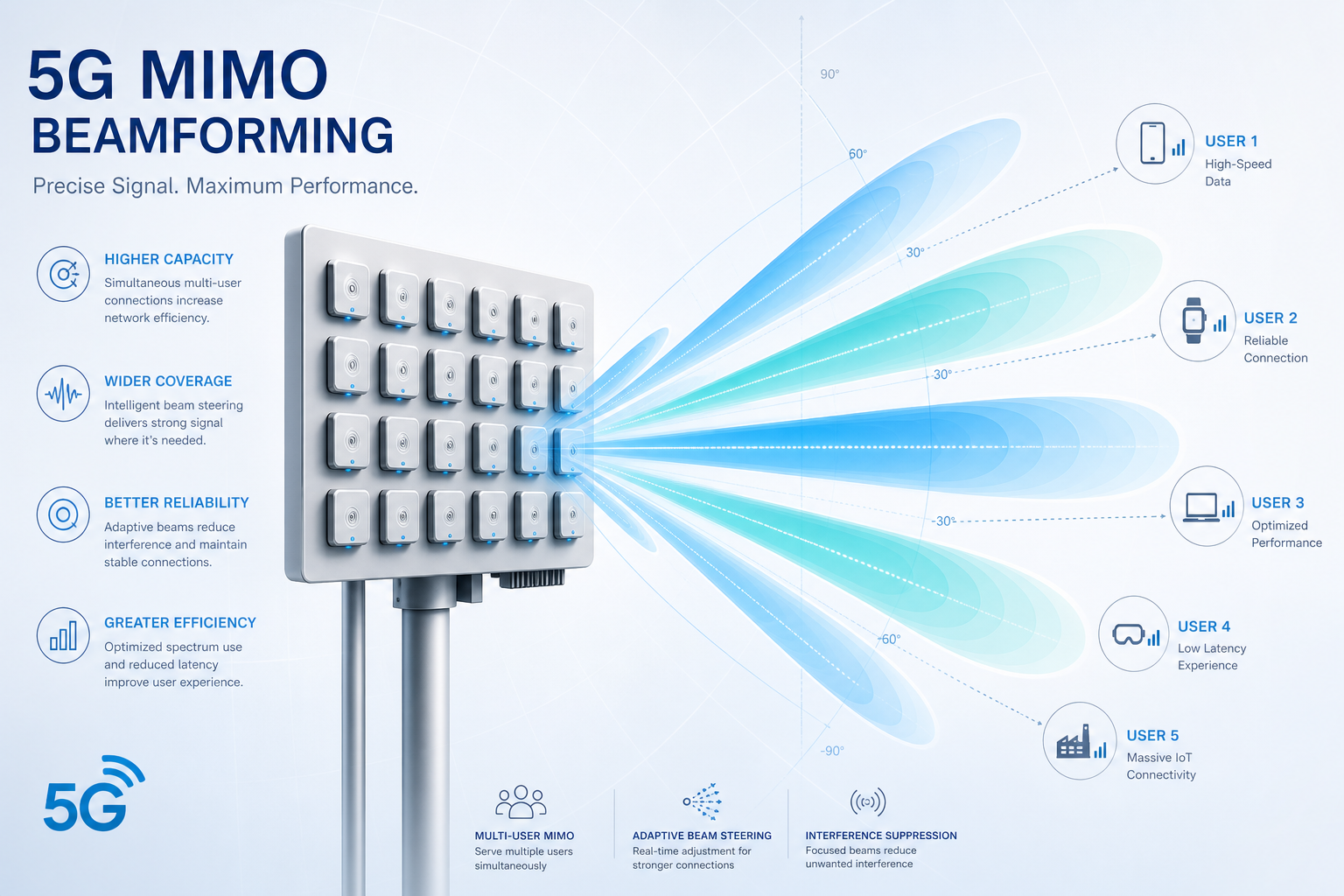
    5G NR introduces sophisticated beam management that distinguishes it from LTE. Beamforming — the ability to shape and steer transmission beams electronically — operates at both the gNB and CPE sides. On the CPE, beamforming is implemented through phased antenna arrays that adjust phase relationships across elements to create constructive interference in the desired direction.

    Several CPE beamforming approaches exist in current commercial devices:

    Switched-Beam Systems. A fixed set of pre-defined beam patterns (typically 4–8) is stored in firmware. The CPE selects the beam pattern yielding the highest RSRP (Reference Signal Received Power). Switched-beam is cost-effective and deterministic but cannot adapt to continuously changing multipath conditions.

    Adaptive Beamforming. The CPE continuously adjusts phase and amplitude weights across antenna elements, steering the beam in real time based on SINR feedback. This approach handles mobility and environmental changes — a delivery truck temporarily blocking the line of sight, for instance — but requires more complex RF front-end and baseband processing.

    Hybrid Beamforming. Combining analog beamforming in the RF domain with digital precoding in baseband, hybrid architectures balance performance and complexity. Most premium 5G CPEs shipping in 2026 use hybrid beamforming, particularly for mmWave (FR2) bands where narrow beams are essential.

    Polarization and Cross-Polarization Discrimination

    5G NR supports dual-polarized transmission, where orthogonal polarizations (typically ±45° slant) carry independent data streams — effectively doubling capacity without additional spectrum. This is standard in 4×4 MIMO configurations, where two polarizations × two physical antenna elements create four effective channels.

    Cross-Polarization Discrimination (XPD) measures how well the CPE antenna maintains polarization separation. Poor XPD causes inter-stream interference, eroding MIMO gains. When evaluating CPE antenna specifications, look for XPD values above 15 dB in the main beam direction. This is particularly critical for outdoor CPE in rainy environments, where depolarization from water droplets on radome surfaces degrades XPD in poorly designed enclosures.

    Internal vs. External Antennas: Deployment Trade-offs

    Internal antennas — integrated within the CPE enclosure — simplify installation and improve industrial design. Modern internal antenna designs using laser-direct structuring (LDS) on molded plastic carriers can achieve gain figures within 1–2 dB of external alternatives in mid-band frequencies. The trade-off is enclosure volume and thermals: antennas need physical separation (typically λ/2, approximately 43 mm at 3.5 GHz), constraining minimum device dimensions.

    External antennas, connected via SMA or TS-9 connectors, offer deployment flexibility. A CPE installed inside a metal-clad building or equipment enclosure may need external antennas mounted outside. External antennas also enable antenna diversity — placing two antennas several wavelengths apart to combat spatial fading. For industrial deployments in challenging RF environments, CPEs with external antenna ports remain the preferred choice, even if internal antennas suffice for benign locations.

    Antenna-to-Modem Integration and RF Front-End Losses

    A specification sheet listing a 5 dBi antenna gain is meaningless if the RF path from antenna to modem introduces 3 dB of insertion loss through connectors, PCB traces, and filters. B2B buyers should request OTA (Over-The-Air) TRP (Total Radiated Power) and TIS (Total Isotropic Sensitivity) measurements — not just antenna datasheet gain — as these capture the end-to-end system performance including all front-end losses. A well-integrated 3 dBi antenna system with low insertion loss can outperform a 6 dBi antenna with 4 dB of path loss.

    Field Validation: What to Measure

    When evaluating CPE antenna performance in the field, four metrics matter most:

    • RSRP (Reference Signal Received Power): Measures the received power of 5G reference signals; above -100 dBm is good, below -115 dBm indicates marginal coverage.
    • SINR (Signal-to-Interference-plus-Noise Ratio): A quality metric; values above 20 dB enable 256QAM modulation and maximum throughput. Values below 10 dB limit modulation to QPSK.
    • Rank Indicator (RI): Reports how many independent MIMO layers the CPE can resolve. An RI of 4 confirms full 4-layer MIMO operation.
    • Throughput stability: Measure throughput variance over hours, not seconds. A CPE that delivers 400 Mbps in a burst test but fluctuates between 100–400 Mbps in sustained operation has an antenna or thermal problem.

    Antenna design is not a commodity feature — it is the differentiating factor that separates a CPE that meets its specification from one that delivers it in the real world. For B2B buyers making procurement decisions at scale, antenna performance evaluation should command as much attention as the modem chipset and software stack combined. In 5G, the best baseband cannot compensate for a compromised RF path.

    Related Resources from Honlly Telecom: