Antenna performance is the single most underestimated variable in 5G CPE procurement. While modem chipsets, firmware stacks, and WAN interfaces dominate specification sheets, the antenna subsystem — its topology, gain, polarization, and beam-steering capability — determines whether a CPE delivers 50 Mbps or 500 Mbps in the same location. For B2B buyers sourcing devices at scale, understanding antenna design is not optional: it is the difference between a successful deployment and a fleet-wide performance gap.
MIMO Configurations: 2×2, 4×4, and Beyond
The MIMO (Multiple-Input Multiple-Output) configuration defines how many independent transmit and receive paths a CPE supports. A 2×2 MIMO CPE uses two antenna elements at each end of the link; a 4×4 MIMO system uses four. The relationship between MIMO layers and throughput is near-linear in good signal conditions — a 4×4 CPE can approximately double the downlink throughput of a 2×2 device on the same cell.
However, the practical benefit depends on the network side. If the gNB (5G base station) is only configured for 2-layer transmission — common in early mid-band deployments — the extra receive paths on a 4×4 CPE still provide diversity gain and improved SINR, but throughput multiplication is limited. B2B buyers should match CPE MIMO order to the operator’s deployed antenna configuration at target sites. For most enterprise deployments accessing 3.5 GHz n78 or C-band n77 networks, 4×4 MIMO is now the baseline recommendation, with 2×2 reserved for cost-sensitive indoor applications where signal conditions are already strong.
Antenna Gain: More Is Not Always Better
Antenna gain, measured in dBi, represents the antenna’s ability to concentrate radiated energy in a particular direction. A high-gain antenna (8–12 dBi) focuses energy into a narrow beam, improving range and signal strength but reducing coverage angular width. Low-gain antennas (2–5 dBi) provide omnidirectional coverage at the expense of range.
For outdoor fixed wireless CPE deployed in suburban or rural settings with a known cell site direction, directional high-gain antennas deliver maximum link budget. For urban indoor CPE where multipath reflections dominate and cell sites may be in multiple directions, moderate-gain omnidirectional or switched-beam antennas often outperform high-gain directional solutions. The procurement decision should be informed by a site survey — or at minimum, by operator-provided coverage maps indicating cell site azimuths relative to deployment locations.
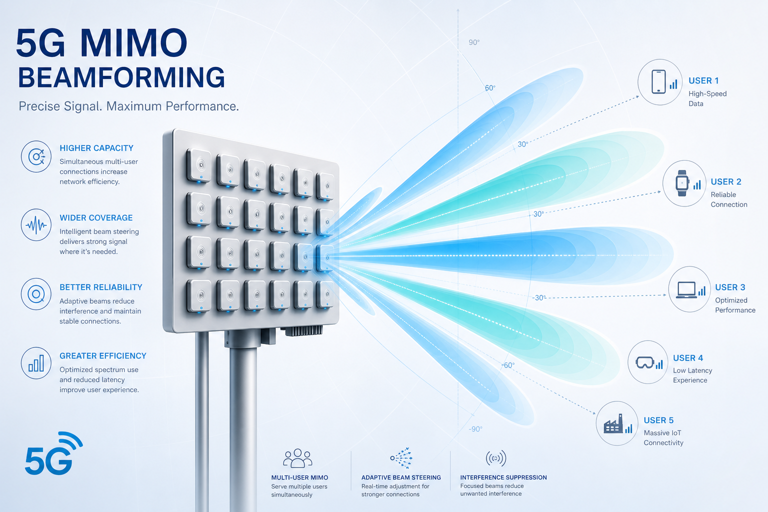
Beamforming and Beam Steering Technologies
5G NR introduces sophisticated beam management that distinguishes it from LTE. Beamforming — the ability to shape and steer transmission beams electronically — operates at both the gNB and CPE sides. On the CPE, beamforming is implemented through phased antenna arrays that adjust phase relationships across elements to create constructive interference in the desired direction.
Several CPE beamforming approaches exist in current commercial devices:
Switched-Beam Systems. A fixed set of pre-defined beam patterns (typically 4–8) is stored in firmware. The CPE selects the beam pattern yielding the highest RSRP (Reference Signal Received Power). Switched-beam is cost-effective and deterministic but cannot adapt to continuously changing multipath conditions.
Adaptive Beamforming. The CPE continuously adjusts phase and amplitude weights across antenna elements, steering the beam in real time based on SINR feedback. This approach handles mobility and environmental changes — a delivery truck temporarily blocking the line of sight, for instance — but requires more complex RF front-end and baseband processing.
Hybrid Beamforming. Combining analog beamforming in the RF domain with digital precoding in baseband, hybrid architectures balance performance and complexity. Most premium 5G CPEs shipping in 2026 use hybrid beamforming, particularly for mmWave (FR2) bands where narrow beams are essential.
Polarization and Cross-Polarization Discrimination
5G NR supports dual-polarized transmission, where orthogonal polarizations (typically ±45° slant) carry independent data streams — effectively doubling capacity without additional spectrum. This is standard in 4×4 MIMO configurations, where two polarizations × two physical antenna elements create four effective channels.
Cross-Polarization Discrimination (XPD) measures how well the CPE antenna maintains polarization separation. Poor XPD causes inter-stream interference, eroding MIMO gains. When evaluating CPE antenna specifications, look for XPD values above 15 dB in the main beam direction. This is particularly critical for outdoor CPE in rainy environments, where depolarization from water droplets on radome surfaces degrades XPD in poorly designed enclosures.
Internal vs. External Antennas: Deployment Trade-offs
Internal antennas — integrated within the CPE enclosure — simplify installation and improve industrial design. Modern internal antenna designs using laser-direct structuring (LDS) on molded plastic carriers can achieve gain figures within 1–2 dB of external alternatives in mid-band frequencies. The trade-off is enclosure volume and thermals: antennas need physical separation (typically λ/2, approximately 43 mm at 3.5 GHz), constraining minimum device dimensions.
External antennas, connected via SMA or TS-9 connectors, offer deployment flexibility. A CPE installed inside a metal-clad building or equipment enclosure may need external antennas mounted outside. External antennas also enable antenna diversity — placing two antennas several wavelengths apart to combat spatial fading. For industrial deployments in challenging RF environments, CPEs with external antenna ports remain the preferred choice, even if internal antennas suffice for benign locations.
Antenna-to-Modem Integration and RF Front-End Losses
A specification sheet listing a 5 dBi antenna gain is meaningless if the RF path from antenna to modem introduces 3 dB of insertion loss through connectors, PCB traces, and filters. B2B buyers should request OTA (Over-The-Air) TRP (Total Radiated Power) and TIS (Total Isotropic Sensitivity) measurements — not just antenna datasheet gain — as these capture the end-to-end system performance including all front-end losses. A well-integrated 3 dBi antenna system with low insertion loss can outperform a 6 dBi antenna with 4 dB of path loss.
Field Validation: What to Measure
When evaluating CPE antenna performance in the field, four metrics matter most:
- RSRP (Reference Signal Received Power): Measures the received power of 5G reference signals; above -100 dBm is good, below -115 dBm indicates marginal coverage.
- SINR (Signal-to-Interference-plus-Noise Ratio): A quality metric; values above 20 dB enable 256QAM modulation and maximum throughput. Values below 10 dB limit modulation to QPSK.
- Rank Indicator (RI): Reports how many independent MIMO layers the CPE can resolve. An RI of 4 confirms full 4-layer MIMO operation.
- Throughput stability: Measure throughput variance over hours, not seconds. A CPE that delivers 400 Mbps in a burst test but fluctuates between 100–400 Mbps in sustained operation has an antenna or thermal problem.
Antenna design is not a commodity feature — it is the differentiating factor that separates a CPE that meets its specification from one that delivers it in the real world. For B2B buyers making procurement decisions at scale, antenna performance evaluation should command as much attention as the modem chipset and software stack combined. In 5G, the best baseband cannot compensate for a compromised RF path.