Category: Blog

Technical guides and best practices

  • Edge Computing on 5G CPE: A Technical Guide to MEC Integration, Local Breakout Architecture, and Enterprise Application Hosting for ISPs and System Integrators

    Edge Computing on 5G CPE: A Technical Guide to MEC Integration, Local Breakout Architecture, and Enterprise Application Hosting for ISPs and System Integrators

    As enterprise networks evolve toward distributed architectures and latency-sensitive applications proliferate, the traditional model of backhauling all traffic to a centralized data center or cloud region is reaching its limits. Multi-access Edge Computing (MEC) integrated with 5G CPE represents a paradigm shift — moving compute, storage, and application logic closer to the point of data generation. For ISPs, system integrators, and enterprise telecom buyers, understanding how to architect, deploy, and manage edge-enabled CPE is rapidly becoming a core competency.

    What Is Edge-Enabled 5G CPE?

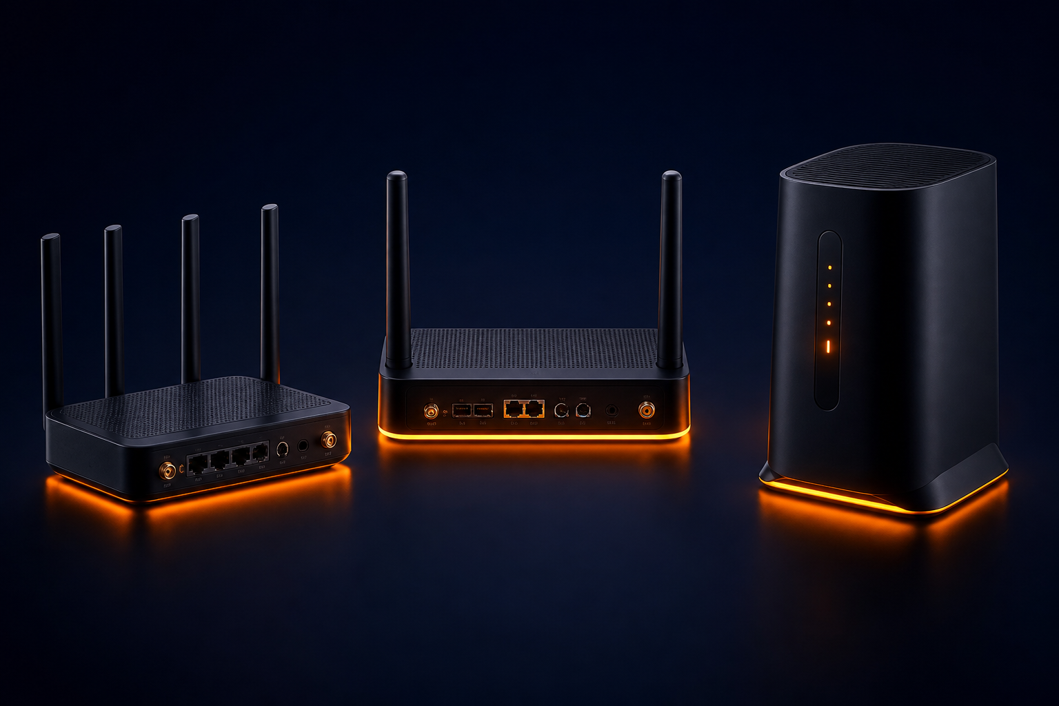
    Edge-enabled 5G CPE combines the wireless WAN connectivity of a 5G NR modem with onboard compute resources capable of hosting containerized or virtualized application workloads at the network edge. Unlike a traditional CPE that functions purely as a Layer 2/3 forwarding device, edge-enabled CPE includes a general-purpose application processor, local storage, and a software execution environment — typically a lightweight Kubernetes distribution, Docker runtime, or vendor-specific application hosting framework.

    The architectural distinction matters: this is not simply a more powerful router. It is a converged platform where WAN termination, LAN switching, security functions, and third-party application workloads coexist on a single device — managed through orchestration frameworks that span thousands of distributed nodes.

    Key Architectural Components

    1. Local Breakout and Traffic Steering

    Local breakout (also called Local Data Network or LDN in 5G terminology) enables the CPE to route selected traffic flows directly to on-premise or nearby edge infrastructure without traversing the mobile core. This is achieved through ULCL (Uplink Classifier) functionality at the UPF (User Plane Function) level in 5G SA architectures, or through application-level traffic steering policies configured on the CPE.

    The practical benefit is dramatic for latency-sensitive workloads: industrial automation control loops that require sub-5ms round-trip time, real-time video analytics that process multiple 4K streams locally, and AR/VR rendering workloads that cannot tolerate the 20-50ms latency of backhaul to a regional cloud data center.

    2. MEC Application Enablement Platform

    The ETSI MEC reference architecture defines the framework for deploying applications at the network edge. For CPE-level implementation, the MEC platform is often a lightweight software stack that provides:

    • Service Registry and Discovery: Enables edge applications to register their availability and discover peer services without centralized DNS or load balancer dependencies.
    • Radio Network Information Service (RNIS): Exposes real-time RAN-level metrics — signal quality, cell load, UE mobility state — to edge applications, enabling radio-aware application optimization.
    • Location Service: Provides geolocation data without GPS dependency, using cell-ID and NR positioning reference signals.
    • Bandwidth Management Service: Allows applications to request guaranteed throughput allocations from the CPE’s traffic scheduler for deterministic performance.

    3. Container Orchestration at the Far Edge

    Deploying containerized workloads on thousands of distributed CPE devices requires orchestration tooling fundamentally different from data center Kubernetes. Lightweight distributions such as K3s, MicroK8s, and the Linux Foundation’s EdgeX Foundry are purpose-built for resource-constrained edge nodes. Key operational considerations include:

    • Image Distribution Efficiency: P2P image distribution protocols (Dragonfly, Kraken) reduce the bandwidth impact of pushing container images to large CPE fleets over WAN links.
    • Graceful Degradation Under Connectivity Loss: The orchestration layer must maintain application availability during WAN link failures, with local image caches and autonomous scheduling decisions.
    • Resource Quotas and Isolation: Applications must operate within strict CPU, memory, and storage bounds to prevent resource starvation of the CPE’s core networking functions.

    Enterprise Use Cases and Deployment Patterns

    Manufacturing and Industry 4.0

    In smart factory deployments, edge-enabled 5G CPE hosts protocol translation gateways (Modbus TCP to OPC UA, PROFINET to MQTT), local SCADA visualization dashboards, and predictive maintenance inference models running on the device NPU. The CPE becomes the converged connectivity-plus-compute node that bridges operational technology (OT) and information technology (IT) networks without requiring separate industrial PCs at each cell.

    Retail and Branch Office

    Multi-site retail operators deploy edge CPE to host local inventory management applications, real-time video analytics for footfall counting and loss prevention, and digital signage content management — all running locally on the CPE device that also provides the store’s primary WAN connectivity. This eliminates the server closet footprint at each location while improving application responsiveness during WAN congestion or outage events.

    Smart Grid and Utility Networks

    Distribution network operators deploy edge CPE at substations to host local phasor measurement unit (PMU) data aggregation, fault detection algorithms, and demand-response logic. The ultra-low latency of local processing — combined with 5G URLLC connectivity to the central SCADA system — enables grid protection schemes that operate within the IEC 61850 4ms transfer time requirement for GOOSE messages.

    Procurement and Integration Considerations for ISPs

    For ISPs and managed service providers evaluating edge-enabled CPE platforms, the following decision criteria should inform RFP specifications:

    Compute Headroom: Specify minimum available CPU cores and RAM for third-party workloads after accounting for baseline CPE functions (routing, firewall, VPN termination). A 4-core ARM Cortex-A78 with 4GB available RAM for applications is a practical minimum for 2026 enterprise deployments.

    NPU/Accelerator Availability: For AI inference workloads at the edge, integrated neural processing units delivering 6-15 TOPS provide sufficient headroom for common models (object detection, anomaly detection, natural language processing). Verify that the NPU SDK supports common model formats (ONNX, TensorFlow Lite, OpenVINO) and that inference pipelines can coexist with networking workloads without QoS degradation.

    Orchestration Platform Compatibility: The CPE platform should integrate with the operator’s existing device management framework (TR-069 ACS or TR-369 USP controller) for base device lifecycle management, while exposing a separate API or agent for application lifecycle management. Avoid vendor-proprietary application orchestration that locks the operator into a single CPE supplier’s ecosystem.

    Security Isolation: Edge applications must execute in a Trusted Execution Environment (TEE) or hardware-enforced container sandbox that prevents compromised applications from accessing CPE networking functions, subscriber credentials, or other tenants’ data in multi-tenant deployment scenarios. Require vendors to document the security isolation architecture and provide penetration test results for the application hosting environment.

    Zero-Touch Application Provisioning: The ability to deploy, update, and decommission edge applications across a fleet of thousands of CPE devices without manual intervention is critical to operational viability. Evaluate the platform’s support for GitOps-style declarative application state management, canary deployment strategies, and automated rollback on health check failure.

    The ETSI MEC Federation Model

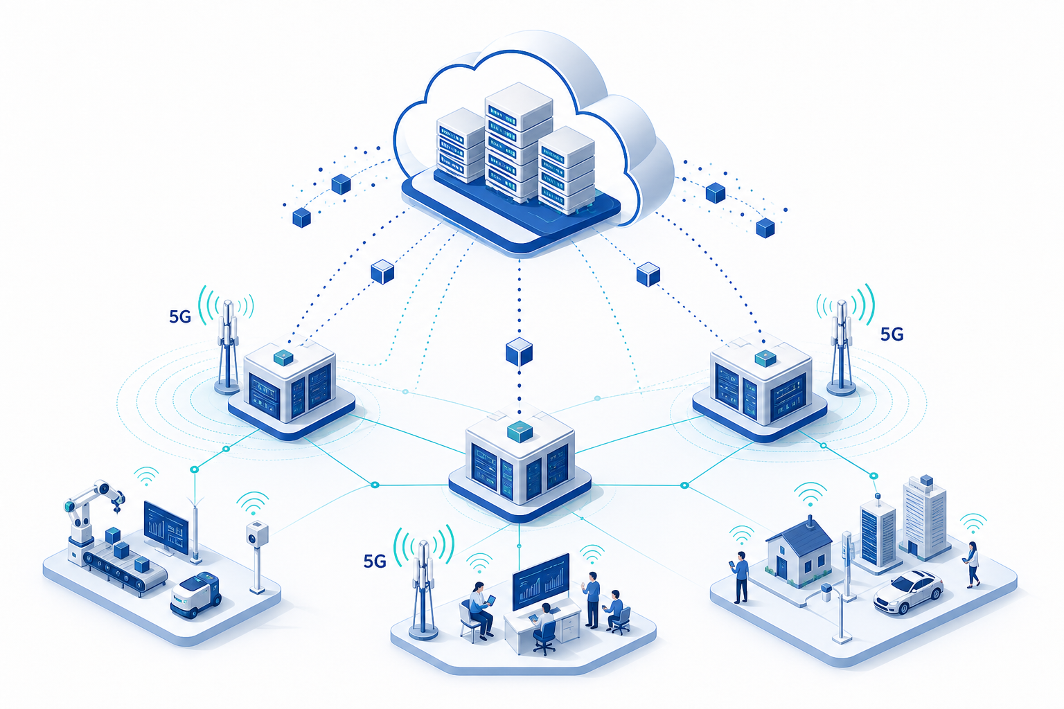
    A emerging architectural pattern is MEC federation, where edge computing resources across multiple administrative domains — operator edge, enterprise on-premise, and hyperscaler edge zones (AWS Wavelength, Azure Edge Zones, Google Distributed Cloud Edge) — are federated into a unified application deployment surface. In this model, the edge-enabled 5G CPE functions as the on-premise node in a hierarchical edge architecture, with workloads able to migrate between CPE, operator MEC, and cloud edge tiers based on latency requirements, resource availability, and cost policies.

    This federation model is particularly relevant for system integrators building multi-site enterprise solutions, where the application deployment topology must flex across hundreds or thousands of locations with heterogeneous edge infrastructure.

    The Road Ahead: 3GPP Release 19 and Beyond

    The 3GPP Release 19 study on “Edge Computing Enhancements” — expected to conclude in Q4 2026 — will introduce standardized APIs for edge application enablement at the 5G system level. Key features under study include:

    • AF-influenced Edge Relocation: Standardized procedures for application function-triggered relocation of edge application contexts between CPE and network edge nodes during UE mobility events.
    • Edge Enabler Client (EEC) on CPE: A standardized client module on the CPE that handles edge service discovery, application context transfer, and capability exposure toward the 5G core network.
    • QoS Monitoring for Edge Applications: Real-time per-flow QoS metrics exposed to edge applications via standardized APIs, enabling adaptive bitrate streaming, dynamic compression level adjustment, and application-level traffic engineering.

    For telecom buyers planning multi-year CPE procurement cycles, selecting platforms with a documented migration path to Release 19 edge computing features — and a silicon roadmap that supports the anticipated compute requirements — is a forward-looking procurement strategy that protects investment in edge-enabled CPE fleets.

  • End-to-End QoS Architecture for Multi-Service 5G CPE: A Technical Guide to Traffic Classification, Hierarchical Shaping, and SLA Enforcement for MVNO and Wholesale Operator Deployments

    End-to-End QoS Architecture for Multi-Service 5G CPE: A Technical Guide to Traffic Classification, Hierarchical Shaping, and SLA Enforcement for MVNO and Wholesale Operator Deployments

    For MVNOs and wholesale operators delivering differentiated service tiers over shared 5G FWA infrastructure, quality of service is not a feature — it is the product. A CPE that cannot enforce per-flow traffic policies, isolate tenant traffic, and deliver carrier-grade SLA assurance is fundamentally incapable of supporting the multi-service business models that make virtual operator economics work. This technical guide provides a comprehensive reference architecture for end-to-end QoS implementation in multi-service 5G CPE — from packet classification at the WAN ingress to hierarchical traffic shaping at the LAN egress — designed for engineering and procurement teams evaluating CPE platforms for commercial multi-tenant deployments.

    The Multi-Service CPE QoS Challenge

    In a traditional single-service operator model, CPE QoS is relatively straightforward: prioritize voice, protect video, manage best-effort data. But MVNOs and wholesale operators face a fundamentally more complex challenge. A single 5G CPE may simultaneously serve:

    • Residential broadband for end-user households (OTT video, web browsing, gaming)
    • Enterprise VPN backhaul for remote branch offices (SLA-backed, latency-sensitive)
    • IoT data aggregation for smart city or industrial sensor networks (low-throughput, high-connection-count)
    • Wholesale capacity resold to sub-operators or community networks (tenant isolation required)

    Each service has distinct throughput, latency, jitter, and availability requirements — and each may map to a different revenue commitment. The CPE must partition a single 5G NR radio link into multiple logical service pipes, each with independently enforceable QoS parameters, while maintaining aggregate link efficiency.

    Reference Architecture: Five-Layer QoS Stack

    The proposed reference architecture organizes CPE QoS functionality into five layers, mirroring the DiffServ and MPLS-TE paradigms adapted for 5G FWA access networks:

    Layer 1: Packet Classification and Marking

    Classification is the foundation. Incoming packets at the CPE WAN-LAN boundary must be identified and marked before any queuing or shaping decision can be made. A production-grade multi-service CPE should support:

    • Multi-field classification (MF-C) based on source/destination IP, L4 protocol, source/destination port, and DSCP/ToS field inspection — implemented in hardware via the CPE SoC’s packet processing engine or programmable switch ASIC
    • Deep Packet Inspection (DPI) for application-layer identification (L7) when services require per-application QoS — e.g., differentiating Microsoft Teams from YouTube within the same broadband service flow
    • VLAN-based service demux at the LAN ingress, where each physical Ethernet port or SSID/VLAN maps to a distinct service instance with its own QoS policy chain
    • 5QI-to-DSCP mapping for translating 3GPP 5G QoS Identifier (5QI) values received from the 5G core into internal DiffServ markings used for LAN-side queuing

    Best practice: implement classification in the CPE data plane (NPU or hardware offload engine) rather than the Linux kernel netfilter path, to avoid CPU-bound classification bottlenecks at multi-gigabit throughput.

    Layer 2: Hierarchical Token Bucket (HTB) Queuing

    Hierarchical Token Bucket is the workhorse of multi-service CPE traffic management. The HTB structure creates a tree of traffic classes where each node has its own committed rate (cir), peak rate (pir), priority, and borrowing rules:

    Root (5G NR Physical Link Capacity: e.g., 500 Mbps CIR, 1 Gbps PIR)

    ├── Service-1: Residential Broadband (CIR: 200 Mbps, PIR: 500 Mbps, Priority: 3)

    │ ├── Leaf: VoIP/IMS (CIR: 5 Mbps, Priority: 0 — strict)

    │ ├── Leaf: OTT Video (CIR: 100 Mbps, Priority: 2)

    │ ├── Leaf: Web/Browsing (CIR: 50 Mbps, Priority: 4)

    │ └── Leaf: Bulk/Downloads (CIR: 45 Mbps, Priority: 5)

    ├── Service-2: Enterprise VPN (CIR: 200 Mbps, PIR: 400 Mbps, Priority: 1)

    │ ├── Leaf: Real-time UC (CIR: 50 Mbps, Priority: 0 — strict)

    │ ├── Leaf: Business Apps (CIR: 100 Mbps, Priority: 2)

    │ └── Leaf: Background Sync (CIR: 50 Mbps, Priority: 5)

    ├── Service-3: IoT Aggregation (CIR: 50 Mbps, PIR: 100 Mbps, Priority: 4)

    │ └── Leaf: Sensor Data (CIR: 50 Mbps, Priority: 4)

    └── Service-4: Wholesale Sub-Operator (CIR: 50 Mbps, PIR: 150 Mbps, Priority: 3)

    └── Leaf: Best Effort (CIR: 50 Mbps, Priority: 3)

    The HTB hierarchy enforces both intra-service QoS (voice prioritized over bulk within the Residential Broadband service) and inter-service isolation (Enterprise VPN guaranteed 200 Mbps regardless of Residential Broadband burst traffic). Borrowing rules allow unused capacity from one service to be temporarily allocated to others, maximizing aggregate link utilization without violating committed rates.

    Layer 3: Per-Service Queue Management (fq_codel / CAKE)

    Below the HTB scheduler, each leaf queue benefits from active queue management (AQM) to control bufferbloat and maintain low latency under load:

    • fq_codel (Fair Queuing + Controlled Delay): Recommended for most service leaves. Provides per-flow fairness and latency control without complex tuning. Suitable for throughput up to ~800 Mbps per queue on typical embedded CPE SoCs.
    • CAKE (Common Applications Kept Enhanced): Preferred for bandwidth-constrained service leaves (e.g., IoT aggregation at 50 Mbps) where precise bandwidth shaping and DiffServ marking preservation are required. CAKE’s integrated shaper eliminates the need for a separate HTB rate limiter on low-throughput leaves.

    Queue depth should be dimensioned per service: 50-100ms of buffering at the committed rate for interactive services, 200-500ms for bulk data services, and sub-20ms for voice/UC leaves.

    Layer 4: 5G NR QoS Framework Integration (5QI Mapping)

    The 5G core’s QoS model — defined in 3GPP TS 23.501 — operates on QoS Flows identified by 5QI values. The CPE must bridge the 3GPP QoS domain (radio bearer level) to the IP QoS domain (DiffServ/DSCP level):

    5QI Resource Type Default Priority Packet Delay Budget Example Service CPE DSCP Mapping
    1 GBR 20 100 ms Conversational Voice EF (46)
    5 Non-GBR 10 100 ms IMS Signalling CS5 (40)
    6 Non-GBR 60 300 ms Video (Buffered) AF41 (34)
    7 Non-GBR 70 100 ms Voice, Video (Live), Gaming AF31 (26)
    8 Non-GBR 80 300 ms TCP-based (Web, Email) DF (0)
    9 Non-GBR 90 300 ms Best Effort / Background CS1 (8)

    The CPE should support rule-based 5QI-to-DSCP mapping at the 5G modem-NPU interface (between the modem’s QoS Flow handler and the NPU’s packet classifier), with the ability to override mappings per service instance. For example, a wholesale operator may map 5QI=8 traffic to CS1 for its own subscribers but re-mark to DF for resold capacity.

    Layer 5: Telemetry and SLA Monitoring

    QoS configuration without measurement is wishful thinking. Production multi-service CPE must export per-service, per-queue telemetry to the operator’s OSS/BSS or assurance platform:

    • Per-service throughput (TX/RX, 1-second and 5-minute averaged) — for SLA compliance reporting
    • Per-queue latency and jitter (P99, P99.9) — for real-time service quality monitoring
    • Per-queue drop count and drop reason — for capacity planning and congestion diagnosis
    • HTB class utilization (actual vs. committed vs. peak) — for service dimensioning
    • Export via IPFIX/NetFlow to operator analytics platform, or gRPC streaming telemetry for near-real-time monitoring

    The CPE should also support configurable SLA threshold alarming: when per-service throughput drops below a committed rate for a configurable consecutive measurement interval (e.g., 3 consecutive 5-minute windows), the CPE generates an SNMP trap or syslog alert upstream.

    Implementation Considerations for CPE Selection

    When evaluating CPE platforms for multi-service QoS deployments, procurement teams should assess:

    Hardware offload capability. Software-based QoS (Linux tc + iptables) is sufficient for sub-500 Mbps aggregate throughput on modern ARM Cortex-A55 or MIPS 1004K CPE SoCs. For multi-gigabit deployments, hardware QoS offload — via the NPU packet processing engine or a dedicated traffic manager ASIC — is essential. Verify that the CPE vendor’s QoS implementation uses hardware acceleration rather than pure Linux kernel queuing, and request benchmark data showing HTB throughput with all service leaves active.

    DPI engine performance. If per-application QoS is required, the CPE’s DPI engine must sustain wire-speed classification at the maximum aggregate throughput. Open-source DPI engines (nDPI, libprotoident) typically deliver 500 Mbps to 1.5 Gbps on embedded SoCs; commercial engines (Sandvine, Procera) can reach 5-10 Gbps but add licensing cost. Match DPI capability to service requirements — many multi-service deployments need only L3/L4 classification, not full DPI.

    Configuration management at scale. A QoS configuration that works beautifully on one CPE is worthless if it cannot be deployed to 100,000 devices. The CPE platform must support QoS policy provisioning via TR-069/TR-369 ACS, NETCONF/YANG, or vendor-specific management API, with atomic configuration commits and rollback-on-failure to prevent QoS misconfiguration at fleet scale.

    Multi-tenant isolation guarantees. For wholesale and MVNO deployments, QoS must extend to tenant isolation. Each tenant’s traffic should be in a separate Linux network namespace or VRFs with independent routing tables and QoS hierarchies. Verify that the CPE platform supports per-VRF QoS — a critical capability often missing in consumer-grade CPE platforms repurposed for operator use.

    Vendor Selection Checklist

    When issuing RFQs for multi-service 5G CPE with QoS requirements, include the following technical evaluation criteria:

    1. Does the platform support Hierarchical Token Bucket (HTB) with a minimum of 4 service levels and 8 leaf classes per service?
    2. Is QoS classification implemented in hardware NPU/data-plane rather than kernel software path?
    3. Does the CPE support DPI-based application classification at line rate? If so, what is the maximum throughput with DPI enabled?
    4. Can QoS policies be provisioned via TR-069/TR-369, NETCONF/YANG, or RESTCONF?
    5. Does the platform support per-VRF QoS for multi-tenant isolation?
    6. Are per-service throughput, latency, jitter, and drop counters exportable via IPFIX or streaming telemetry?
    7. Can the CPE generate alarms when per-service throughput drops below committed rate?
    8. Is the 5QI-to-DSCP mapping table configurable per service instance?
    9. Does QoS configuration survive firmware upgrades and factory resets without operator re-provisioning?
    10. Has the vendor published benchmark data for HTB performance under maximum service configuration?

    QoS architecture is not an afterthought for multi-service CPE — it is the fundamental capability that determines whether an MVNO or wholesale operator can deliver on its commercial commitments. The reference architecture described here provides a structured framework for evaluating CPE platforms, designing service hierarchies, and implementing carrier-grade SLA enforcement at the network edge. For operators building 2027 CPE procurement specifications, QoS capabilities should be weighted as a tier-1 evaluation criterion alongside radio performance, cost, and management platform integration.


    References: 3GPP TS 23.501 (System Architecture for the 5G System); RFC 4594 (Configuration Guidelines for DiffServ Service Classes); Broadband Forum TR-181 (Device Data Model for TR-069); Linux tc-htb manual; IETF RFC 7010 (IPFIX for Flow Measurement).

  • A Field Engineer’s Guide to 5G FWA Site Survey and CPE Installation: From Signal Measurement to Throughput Verification

    A Field Engineer’s Guide to 5G FWA Site Survey and CPE Installation: From Signal Measurement to Throughput Verification

    A properly executed site survey is the single most important factor determining whether a 5G fixed wireless access (FWA) deployment delivers the throughput and reliability your customers expect—or generates a steady stream of support tickets. Yet in the rush to scale FWA rollouts, many operators and integrators shortcut this critical step, relying on coverage maps and best-guess antenna placement rather than methodical field measurements.

    This guide provides a structured, repeatable methodology for 5G FWA site surveys and outdoor CPE installation. It is designed for field engineers, deployment managers, and technical teams at ISPs, operators, and system integrators who need to deliver consistent installation quality at scale.

    Phase 1: Pre-Installation Preparation

    1.1 Tools and Equipment Checklist

    Before heading to the site, ensure your field kit includes:

    • Spectrum/signal analyzer: A handheld 5G NR-capable analyzer supporting FR1 (sub-6 GHz) and, if applicable, FR2 (mmWave) bands. Rohde & Schwarz, Keysight, and Anritsu offer field-portable options. For budget-constrained operations, smartphone-based tools like G-NetTrack Pro or NSG can provide adequate baseline measurements when calibrated against a reference device.
    • Candidate CPE device: The exact CPE model planned for deployment, loaded with engineering firmware that exposes RSRP, RSRQ, SINR, and PCI readings. Generic measurement tools cannot substitute for the actual CPE’s antenna and modem characteristics.
    • Mounting test pole: A telescoping pole (3–6 meters) with temporary bracket for testing antenna positions at planned mounting heights.
    • GPS receiver or smartphone: For recording precise coordinates and azimuth angles at each test position.
    • Laptop/tablet: Running iPerf3 or equivalent for throughput testing, plus a spreadsheet or survey app for structured data capture.
    • Compass and inclinometer: For recording antenna azimuth and tilt angles.
    • Weather-appropriate PPE: Harness, helmet, gloves for rooftop work; sun protection for extended outdoor surveys.

    1.2 Pre-Survey Intelligence Gathering

    Before leaving the office, collect the following information:

    • Operator coverage maps: Download the latest 5G coverage data for the target address. Note the nearest cell site locations, azimuth directions, and estimated distances.
    • Spectrum bands deployed: Identify which NR bands (n78, n41, n77, n1, n3, n28, etc.) are active at the target location and their channel bandwidths. This determines whether the deployment will leverage mid-band capacity or rely on low-band coverage.
    • Site photographs (Google Earth/Street View): Preview the building orientation, roofline, surrounding structures, and potential obstructions (trees, adjacent buildings, water towers).
    • Customer requirements: Confirmed throughput targets (downlink and uplink), number of concurrent users, application profile (e.g., general internet vs. VoIP/video conferencing vs. industrial IoT), and any specific SLA commitments.

    Phase 2: On-Site Signal Survey

    2.1 Exterior Signal Assessment

    Begin with a walk-around survey of the building exterior. The goal is to identify the optimal azimuth direction and mounting position before committing to a fixed installation.

    Step 1 — Perimeter Scan: Walk a complete circuit of the building at ground level, stopping every 5–10 meters to record RSRP, RSRQ, and SINR values from the candidate CPE. Hold the device at arm’s length, oriented toward the exterior wall, and rotate through 360° at each position. Record the best and worst azimuths.

    Step 2 — Rooftop/Balcony Assessment: If accessible, repeat the perimeter scan at the planned mounting height. Signal quality at 5 meters above ground can differ dramatically from ground-level readings, particularly in urban environments with street-level canyon effects. Use the test pole to simulate the final antenna position.

    Step 3 — Line-of-Sight Verification: For deployments targeting mmWave or high-frequency mid-band (n78/n77), visually confirm line-of-sight to the serving cell site. Even partial obstructions—building corners, tree canopies, signage—can cause 10–20 dB of signal attenuation at frequencies above 3.5 GHz. Use binoculars or a camera with telephoto lens if the cell site is not visible to the naked eye.

    2.2 Signal Quality Thresholds

    Record and evaluate measurements against these recommended minimum thresholds for a production-grade 5G FWA installation:

    MetricExcellentGoodAdequateUnacceptable
    RSRP (dBm)> −85−85 to −95−95 to −105< −105
    RSRQ (dB)> −10−10 to −15−15 to −18< −18
    SINR (dB)> 2010 to 205 to 10< 5

    If the best measured position falls into the “Adequate” range, consider whether a higher-gain directional antenna or an alternative mounting location can improve signal quality. “Unacceptable” readings indicate that the site may require an outdoor CPE with high-gain antenna array, a different operator’s service, or should be deferred until network densification improves coverage.

    Phase 3: Antenna Positioning and Optimization

    3.1 Directional Antenna Alignment

    For outdoor CPE with integrated or external directional antennas, precise alignment toward the serving cell is critical. A 10° misalignment on a high-gain antenna can reduce received signal strength by 3–6 dB.

    Alignment Procedure:

    1. Identify the Physical Cell ID (PCI) of the strongest detected cell.
    2. Using the pre-survey cell site location data, calculate the azimuth bearing from the installation site to the target cell.
    3. Mount the CPE temporarily on the test pole at the planned height and position.
    4. Slowly sweep the azimuth ±30° from the calculated bearing while monitoring real-time RSRP and SINR.
    5. Lock the azimuth at the position yielding the highest SINR—not necessarily the highest RSRP. SINR is the stronger predictor of achievable throughput.
    6. Adjust tilt (elevation) to fine-tune, especially if the cell site is at a significantly different elevation.

    3.2 MIMO Antenna Considerations

    Modern 5G CPE devices typically implement 2×2 or 4×4 MIMO. For external antenna installations, ensure:

    • Antenna elements are separated by at least λ/2 (approximately 4.3 cm at 3.5 GHz) to maintain spatial diversity.
    • Cross-polarized antenna pairs (+45°/−45°) are oriented correctly to match the cell site’s polarization configuration.
    • Multiple antenna panels are pointed at the same serving cell—splitting across different cells can degrade MIMO rank and reduce throughput.

    Phase 4: Throughput Verification

    4.1 Benchmark Testing Protocol

    Once the CPE is positioned at the optimal location, conduct structured throughput tests before finalizing the installation:

    1. Idle Throughput Test: Run iPerf3 TCP for 60 seconds with no other traffic on the link. Record average and 95th percentile throughput in both downlink and uplink directions.
    2. Concurrent Load Test: Simulate the expected multi-user scenario by running 3–5 parallel iPerf3 TCP streams. This stresses the CPE’s buffer management and reveals throughput degradation under concurrent load.
    3. Latency Under Load Test: Run continuous ICMP pings (1-second interval) to a nearby server while the iPerf3 TCP test is active. Document the increase in RTT compared to idle conditions. Bufferbloat exceeding 50 ms of added latency warrants QoS tuning on the CPE.
    4. Stability Test: Monitor RSRP, SINR, and PCI for a minimum of 15 minutes. Look for cell reselection events, signal fluctuations exceeding ±5 dB, or PCI changes that indicate handover to a weaker cell.

    4.2 Acceptance Criteria

    A 5G FWA installation meets acceptance criteria when:

    • Downlink throughput ≥80% of the operator’s advertised speed tier for the site location.
    • SINR remains stable within a 5 dB band over the observation period.
    • No cell reselection or PCI changes during the stability test.
    • Latency under load does not increase by more than 30 ms over idle RTT.

    Document all measurements with timestamps, GPS coordinates, and photographs of the final installation. This data is invaluable for troubleshooting future performance issues and demonstrating installation quality to customers.

    Phase 5: Common Pitfalls and Troubleshooting

    SymptomLikely CauseRemediation
    Good RSRP but poor SINRStrong interference from adjacent cell or non-cellular sourceAdjust azimuth to favor serving cell; consider band-locking to a cleaner channel
    Good signal but low throughputCell congestion or backhaul limitationTest at off-peak hours to isolate; escalate to operator if confirmed
    Frequent PCI changesPing-pong handover between cells of similar strengthPCI lock on CPE; adjust antenna to increase dominance of preferred cell
    High latency under loadBufferbloat on CPE or operator core networkEnable AQM/CoDel on CPE; apply traffic shaping below link capacity
    Uplink significantly below expectationsTDD frame configuration favors downlink; low UE transmit powerVerify TDD pattern with operator; reposition CPE to reduce uplink path loss

    Site Survey Documentation Checklist

    Complete this checklist for every installation and attach it to the deployment record:

    • ☐ Site address and GPS coordinates
    • ☐ Installer name and date
    • ☐ Operator and service plan details
    • ☐ CPE model, firmware version, and IMEI
    • ☐ Best-position measurements: RSRP ____ dBm | RSRQ ____ dB | SINR ____ dB | PCI ____
    • ☐ Final antenna azimuth: ____ ° | Tilt: ____ ° | Mounting height: ____ m
    • ☐ Throughput test results: DL ____ Mbps | UL ____ Mbps | Latency (idle) ____ ms | Latency (load) ____ ms
    • ☐ Stability observation period: ____ minutes | PCI changes: ____
    • ☐ Photographs: Installation position, surrounding environment from antenna perspective, CPE mounting detail
    • ☐ Customer sign-off

    FAQ

    What is the most common mistake in 5G FWA site surveys?

    The most frequent error is relying solely on smartphone-based signal readings rather than testing with the actual CPE device that will be deployed. Smartphone antennas, modem capabilities, and MIMO configurations differ significantly from dedicated FWA CPE, often producing misleading signal quality estimates.

    How long should a typical 5G FWA site survey take?

    A thorough residential or small-business survey typically takes 45–90 minutes, including perimeter scans, rooftop assessment, antenna alignment optimization, and throughput verification. Large enterprise or multi-floor installations may require 2–4 hours.

    Can I use a drone for rooftop signal assessment?

    Yes, drone-based surveys are increasingly common for multi-story buildings and industrial sites where rooftop access is restricted. However, drone-mounted measurement equipment must be lightweight and the surveyor must account for drone body effects on antenna patterns. Always comply with local aviation regulations.

    What should I do if no position meets the minimum signal thresholds?

    Consider these escalation options: (1) install an outdoor CPE with a higher-gain directional antenna array, (2) explore external antenna options with longer cable runs to reach a better signal position, (3) evaluate an alternative operator’s coverage at the site, or (4) defer the installation and flag the address for network densification review.

    Looking for carrier-grade 5G FWA CPE with flexible antenna options for your deployment projects? Contact Honlly Telecom to discuss our outdoor and indoor 5G CPE portfolio, including models with external antenna support and engineering-mode diagnostic access for professional site surveys.

  • 5G NR-U (NR in Unlicensed Spectrum) for Enterprise CPE: A Technical Guide to License-Assisted Access, Standalone NR-U, and Private Network Deployment Architectures

    5G NR-U (NR in Unlicensed Spectrum) for Enterprise CPE: A Technical Guide to License-Assisted Access, Standalone NR-U, and Private Network Deployment Architectures

    As the global demand for private wireless networks accelerates, enterprises and system integrators are increasingly exploring spectrum options beyond traditional licensed bands. 5G NR-U (New Radio in Unlicensed Spectrum) has emerged as a compelling alternative, offering the performance characteristics of 5G NR without the cost and complexity of spectrum licensing. For operators, MVNOs, and enterprise IT buyers evaluating CPE deployments, understanding the NR-U landscape is essential to making informed architecture decisions in 2026.

    This technical guide provides a comprehensive overview of 5G NR-U technology, its deployment architectures, and practical considerations for CPE selection. Whether you are planning a private 5G network for a manufacturing campus, a neutral host deployment in a multi-tenant building, or a cost-optimized FWA rollout in unlicensed spectrum, the information below will help you navigate the technology and procurement landscape.

    Understanding 5G NR-U: LAA vs Standalone NR-U

    3GPP defined two operational modes for 5G NR in unlicensed spectrum, each serving distinct deployment scenarios:

    License-Assisted Access (LAA): Specified in 3GPP Release 15 and enhanced in Release 16, LAA requires an anchor carrier in licensed spectrum. The primary cell (PCell) operates in licensed bands, while one or more secondary cells (SCells) aggregate unlicensed carriers to boost throughput. This model is well-suited for operators who already hold licensed spectrum and want to augment capacity in high-density areas. LAA-capable CPE must support carrier aggregation across licensed and unlicensed bands, which adds modem complexity but preserves the reliability of licensed-spectrum control signaling.

    Standalone NR-U (sNR-U): Introduced in 3GPP Release 16, sNR-U operates entirely in unlicensed spectrum without requiring a licensed anchor. This is the architecture of choice for private 5G networks, enterprise campus deployments, and neutral host networks where the deploying organization does not hold spectrum licenses. sNR-U CPE must implement robust coexistence mechanisms—primarily Listen-Before-Talk (LBT)—to share spectrum fairly with Wi-Fi and other unlicensed technologies.

    For CPE procurement, the choice between LAA and sNR-U has significant implications for modem selection, antenna design, and certification requirements. LAA CPE benefits from the mature ecosystem of licensed-band 5G modems, while sNR-U CPE requires chipsets with dedicated unlicensed-band RF front-ends and LBT firmware support.

    Spectrum Options: 5 GHz, 6 GHz, and the Global Regulatory Landscape

    The availability of unlicensed spectrum for NR-U operation varies by region, and CPE hardware must be configured accordingly:

    • 5 GHz Band (5.15–5.925 GHz): The most universally available unlicensed band, already shared by Wi-Fi 5, Wi-Fi 6, and Wi-Fi 6E. NR-U in 5 GHz must coexist with existing Wi-Fi deployments, which is technically feasible through LBT but practically challenging in Wi-Fi-dense environments. Most first-generation sNR-U CPE targets the 5 GHz band due to broad regulatory approval.
    • 6 GHz Band (5.925–7.125 GHz): The “greenfield” unlicensed spectrum opened by regulators in the US (FCC), Europe (CEPT), and select Asia-Pacific markets. With 1,200 MHz of bandwidth available, the 6 GHz band offers significantly more capacity for NR-U deployments. However, regulatory frameworks differ: the US permits unlicensed use across the full band, while Europe and other regions have implemented portions as license-exempt with varying power limits. CPE targeting multi-region deployment must support configurable band masks and power profiles.
    • mmWave Unlicensed (57–71 GHz): While technically available for NR-U, mmWave unlicensed bands present practical challenges for CPE due to propagation limitations and the need for beamforming. Most NR-U CPE development through 2026 focuses on sub-7 GHz bands.

    CPE buyers should verify that target devices support the specific unlicensed band allocations in their deployment region, including DFS (Dynamic Frequency Selection) compliance where required for 5 GHz operation.

    Architectural Models for NR-U Enterprise CPE Deployment

    NR-U supports several deployment architectures that are relevant to enterprise and operator CPE procurement:

    Standalone Private 5G (SNPN): A fully self-contained 5G network operating exclusively in unlicensed spectrum, using sNR-U for both the radio access network and device connectivity. This model is ideal for industrial campuses, logistics centers, and enterprise facilities where the organization controls both the network infrastructure and CPE endpoints. CPE for SNPN deployments should support network slicing to isolate traffic classes and URLLC features for time-sensitive industrial applications.

    Neutral Host Network (NHN): A shared radio access infrastructure deployed by a third-party neutral host provider, serving multiple tenant operators or enterprises from a common NR-U RAN. CPE in NHN architectures must support multi-PLMN selection and potentially eSIM-based credential management to facilitate tenant onboarding and mobility between shared and dedicated spectrum resources.

    Hybrid Licensed-Unlicensed Aggregation: Operators with licensed spectrum holdings can deploy CPE that aggregates licensed carriers (for control plane reliability and baseline coverage) with NR-U carriers (for capacity augmentation). This hybrid model is popular among Tier-2 and Tier-3 operators seeking to expand FWA capacity without additional spectrum acquisition costs.

    Coexistence Mechanisms: LBT and Shared Spectrum Efficiency

    The defining technical challenge of NR-U is fair coexistence with Wi-Fi and other unlicensed spectrum users. 3GPP specified several mechanisms to ensure NR-U operates as a “good neighbor” in shared spectrum:

    Listen-Before-Talk (LBT): The foundational coexistence mechanism, requiring NR-U transmitters to sense the channel for a defined period before transmission. If the channel is occupied, the transmitter defers access using a contention window that doubles on collision, similar to Wi-Fi’s CSMA/CA protocol. 3GPP defined two LBT categories—Category 2 (fixed sensing period without random backoff) and Category 4 (variable contention window with exponential backoff)—with Category 4 being the default for data transmission.

    Channel Occupancy Time (COT) Sharing: NR-U allows a gNB that has acquired the channel to share its COT with connected CPE devices, reducing the number of LBT operations required and improving overall spectral efficiency. Intelligent COT scheduling is critical to NR-U performance, as excessive LBT overhead can negate the throughput advantages of 5G NR over Wi-Fi.

    Wideband Operation with Sub-Band LBT: For deployments using wide carriers (40 MHz, 80 MHz, or 100 MHz), NR-U supports sub-band LBT where the carrier is divided into 20 MHz sub-bands, each independently subject to LBT. If interference is detected on one sub-band, the transmission can proceed on others, providing resilience in congested spectrum environments.

    Private 5G Networks with NR-U: A Cost-Effective Path

    For enterprises evaluating private 5G, NR-U offers a significantly lower barrier to entry compared to licensed-spectrum deployments. The elimination of spectrum licensing fees—which can range from $50,000 to multiple millions depending on country and bandwidth—makes private 5G accessible to mid-market enterprises that previously could not justify the investment.

    However, CPE buyers should understand the trade-offs. NR-U networks in shared spectrum do not offer the same interference guarantees as licensed-spectrum private 5G. In busy industrial environments with heavy Wi-Fi usage, NR-U performance may degrade during peak Wi-Fi activity. System integrators should conduct thorough site surveys and RF planning before committing to an all-NR-U architecture, and consider hybrid models that reserve licensed spectrum for critical control traffic while offloading bulk data to NR-U carriers.

    Device ecosystem maturity is another consideration. While the number of NR-U-capable CPE and module vendors is growing rapidly in 2026, the ecosystem is smaller than that for licensed-band 5G. Buyers should verify NR-U interoperability with their chosen small cell or gNB vendor before procurement.

    CPE Hardware Requirements for NR-U Support

    NR-U-capable CPE requires specific hardware capabilities beyond standard 5G NR CPE:

    • Unlicensed-band RF Front-End: Dedicated receive and transmit chains covering 5 GHz and/or 6 GHz unlicensed bands, with sufficient linearity and filtering to operate in shared spectrum without causing or receiving adjacent-channel interference.
    • LBT Firmware: CPE modem firmware must implement 3GPP-compliant LBT procedures, including energy detection threshold configuration, contention window management, and COT sharing logic. LBT performance directly impacts NR-U throughput, making modem firmware quality a key procurement criterion.
    • DFS/Radar Detection: CPE operating in 5 GHz DFS channels must implement radar detection and dynamic frequency selection, vacating channels when radar signals are detected. This requires both hardware detection capability and regulatory certification in each target market.
    • Multi-band Carrier Aggregation: For hybrid deployment models, the CPE modem must support carrier aggregation combining licensed and unlicensed component carriers, with independent RF chains for each band.
    • GNSS/1588 Timing: NR-U TDD operation requires precise timing synchronization. CPE should support either GNSS-disciplined oscillators or IEEE 1588v2 Precision Time Protocol for phase alignment across the network.

    Honlly’s NR-U-Ready CPE Portfolio

    Honlly Telecom is actively developing NR-U-capable CPE platforms targeting the enterprise private 5G and neutral host deployment markets. The next-generation HL-860 series platform, sampling in Q3 2026, will feature native support for sNR-U operation in the 5 GHz and 6 GHz bands, with integrated LBT firmware, DFS radar detection, and multi-band carrier aggregation across licensed and unlicensed spectrum. Engineering samples and technical specifications are available to qualified operator and system integrator partners under NDA.

    For procurement teams planning private 5G or NR-U-enhanced FWA deployments, Honlly’s solutions engineering team offers consultation on CPE selection, network architecture, and RF planning. Contact sales@xmhonlly.com to discuss your NR-U deployment requirements and receive a tailored CPE recommendation.

    Key Takeaways for CPE Buyers:

    • NR-U offers a cost-effective path to private 5G without spectrum licensing fees
    • Choose between LAA (licensed anchor required) and sNR-U (fully unlicensed) based on spectrum availability and deployment model
    • Verify CPE band support, LBT firmware quality, and DFS certification for target deployment regions
    • Conduct RF site surveys to assess Wi-Fi coexistence risk before committing to sNR-U architecture
    • Hybrid licensed-unlicensed aggregation provides the best balance of reliability and capacity for operator deployments
  • 5G CPE Total Cost of Ownership Analysis for ISP Procurement: CAPEX, OPEX, and Lifecycle Economics for Fixed Wireless Access Rollouts

    5G CPE Total Cost of Ownership Analysis for ISP Procurement: CAPEX, OPEX, and Lifecycle Economics for Fixed Wireless Access Rollouts

    For ISPs and telecom operators planning Fixed Wireless Access (FWA) rollouts, the per-unit purchase price of a 5G CPE represents only the tip of the financial iceberg. A comprehensive Total Cost of Ownership (TCO) analysis — spanning hardware acquisition, deployment logistics, ongoing operations, lifecycle management, and end-of-life disposal — often reveals that the initial CAPEX decision accounts for less than 35% of the total five-year cost per subscriber. This guide provides a structured TCO framework for procurement teams evaluating 5G CPE options in 2026.

    The Five-Year TCO Model: Beyond the Unit Price

    A robust 5G CPE TCO model for ISP deployments should account for the following cost categories across a five-year device lifecycle:

    TCO CategoryTypical Share of 5-Year CostKey Variables
    Hardware CAPEX30–35%Unit price, volume discounts, import duties, logistics
    Deployment & Installation12–18%Truck roll cost, self-install ratio, activation failure rate
    Ongoing Operations25–30%Support tickets, firmware updates, ACS platform costs
    Returns & Replacements8–12%DOA rate, field failure rate, warranty terms, RMA logistics
    End-of-Life Management3–5%Reverse logistics, refurbishment, e-waste compliance
    Network/Core Integration5–8%ACS licensing, TR-069/TR-369 server scaling, integration engineering

    This distribution highlights a critical insight: choosing a CPE based primarily on the lowest unit price often increases total cost when deployment complexity, support burden, and failure rates are factored in.

    CAPEX Deep Dive: What Drives the Unit Price

    The bill-of-materials (BOM) cost of a 5G CPE in 2026 is dominated by four components:

    Modem-RF Platform (35–45% of BOM)

    The choice between Qualcomm Snapdragon X75/X80, MediaTek T830, or UNISOC V516 platforms significantly impacts both upfront cost and long-term performance. Qualcomm platforms command a $12–18 premium but offer broader carrier certification coverage and longer software support commitments (typically 5+ years). MediaTek’s T830 provides competitive performance at 15–20% lower cost, making it attractive for price-sensitive markets. UNISOC platforms serve the sub-$60 BOM segment for basic connectivity use cases.

    Wi-Fi Subsystem (8–12% of BOM)

    Wi-Fi 7 (802.11be) chipsets add approximately $15–22 over Wi-Fi 6 equivalents. However, operators deploying Wi-Fi 7 CPE report 18–22% fewer in-home coverage-related support calls, translating to annual OPEX savings of $3–5 per subscriber. For deployments exceeding 50,000 units, the Wi-Fi 7 premium typically pays back within 14–18 months through reduced support costs alone.

    Memory and Storage (6–9% of BOM)

    5G CPE typically requires 512 MB–1 GB LPDDR4X RAM and 256 MB–512 MB flash storage. Operators planning to deploy value-added services (VPN termination, edge compute containers, local traffic analytics) should specify 1 GB RAM minimum to avoid premature obsolescence and costly field replacements.

    Enclosure and Thermal Design (5–8% of BOM)

    Passive thermal design quality directly correlates with field failure rates. CPE using extruded aluminum heatsinks and optimized airflow paths typically show 40–60% lower failure rates over five years compared to plastic-only enclosures with basic ventilation. The $1.50–3.00 incremental BOM cost for improved thermal design is among the highest-ROI investments in CPE specification.

    OPEX: The Hidden Cost Multiplier

    Self-Install vs. Truck Roll Economics

    The single largest OPEX variable in FWA CPE deployment is the self-install success rate. Operators achieving self-install rates above 85% report average deployment costs of $18–35 per subscriber. Those relying primarily on technician visits face $85–150 per installation. Key CPE design factors that improve self-install success include:

    • Guided setup mobile apps with signal-strength-based placement optimization (reduces install failure by 35–40%)
    • eSIM-based zero-touch provisioning eliminating manual APN and carrier configuration (reduces support calls by 22–28%)
    • LED-free “stealth” design options for residential deployments where blinking lights trigger unnecessary support inquiries

    Support Ticket Economics

    Industry benchmarks show that the average 5G FWA CPE generates 0.8–1.4 support contacts per year. At an average cost of $12–18 per handled ticket (including L1 and L2 support), annual per-subscriber support costs range from $9.60 to $25.20. CPE with integrated remote diagnostics capabilities (TR-369 USP-based performance monitoring, Wi-Fi experience scoring) reduce ticket volume by 30–40%.

    Firmware Lifecycle Management

    Over a five-year lifecycle, a typical 5G CPE receives 8–15 firmware updates. Each OTA update carries bandwidth costs ($0.02–0.08 per device per update depending on payload size) and engineering costs for testing and staged rollout management. Operators should verify that CPE vendors commit to a minimum 5-year firmware support window and provide FOTA (Firmware Over-The-Air) delta update capability to minimize bandwidth consumption.

    Returns, RMAs, and Field Failure: The Cost of Unreliability

    Field failure rates for 5G CPE in the first 12 months currently average 2.5–5.0% across the industry, with best-in-class models achieving sub-1.5%. Each field failure incurs:

    • Customer support handling: $15–25 (troubleshooting, diagnosis)
    • Replacement unit cost: 100% of unit price (plus shipping)
    • Reverse logistics: $8–15 (return shipping, receiving, testing)
    • Customer churn risk: 15–25% of subscribers experiencing CPE failure churn within 60 days, representing $250–600 in lost lifetime value per churned subscriber

    For a 100,000-subscriber deployment, a 2% improvement in annual failure rate (from 4% to 2%) translates to approximately $1.2–1.8 million in annual savings — far exceeding any upfront unit price premium for higher-quality CPE.

    TCO Optimization Framework: Six Decision Criteria

    When evaluating 5G CPE options, procurement teams should weight their decision across these six criteria:

    1. Five-year TCO per subscriber (not unit price) — target below $180 for Sub-6 GHz, below $250 for mmWave CPE
    2. Self-install success rate target — minimum 80%, with contractual vendor commitments
    3. Annual field failure rate — maximum 2.5% in year 1, 1.5% in years 2–5
    4. Firmware support window — minimum 5 years from first shipment, with quarterly security patches
    5. TR-369 USP compliance — mandatory for remote diagnostics and proactive fault detection
    6. Wi-Fi 7 readiness — strongly recommended for greenfield deployments; Wi-Fi 6E as minimum fallback

    Case Study: The ROI of Quality-Driven CPE Selection

    Consider a hypothetical ISP deploying 50,000 FWA subscribers:

    • Option A: Low-cost CPE at $65/unit, 4.5% annual failure rate, 72% self-install success, Wi-Fi 6, 3-year firmware support
    • Option B: Quality CPE at $82/unit, 1.8% annual failure rate, 87% self-install success, Wi-Fi 7, 5-year firmware support

    The 5-year TCO analysis tells a clear story:

    • Option A 5-Year TCO: $10.8 million ($216/subscriber)
      • Hardware: $3.25M | Deployment: $2.4M | Support: $2.8M | Returns: $1.5M | Other: $0.85M
    • Option B 5-Year TCO: $8.9 million ($178/subscriber)
      • Hardware: $4.1M | Deployment: $1.2M | Support: $1.6M | Returns: $0.65M | Other: $1.35M

    The higher-quality CPE saves $1.9 million over five years — $38 per subscriber — despite a $17 higher unit price. This is the power of TCO-driven procurement.

    Conclusion: TCO Thinking as a Competitive Advantage

    In the increasingly competitive FWA market, operators that adopt TCO-based CPE procurement consistently outperform those making decisions on unit price alone. The key takeaway for ISP and operator procurement teams: demand TCO data from your CPE vendors. Request field failure rate statistics, self-install success benchmarks from reference deployments, and contractual commitments on firmware support duration. The lowest unit price rarely delivers the lowest total cost — and in the subscriber business, total cost is what determines profitability.


    This analysis draws on operator deployment data, CPE vendor specifications, and industry benchmarks from Omdia, ABI Research, and GSMA Intelligence 2026 reports.

  • Cloud-Native CPE Fleet Management Platforms: A Technical Buyer’s Guide to Zero-Touch Provisioning, TR-069/TR-369 ACS Selection, and Multi-Tenant Orchestration for ISPs

    Cloud-Native CPE Fleet Management Platforms: A Technical Buyer’s Guide to Zero-Touch Provisioning, TR-069/TR-369 ACS Selection, and Multi-Tenant Orchestration for ISPs

    As telecom operators and ISPs scale their CPE deployments from hundreds to tens of thousands of devices, the operational burden of manual device provisioning, firmware management, and fault remediation becomes unsustainable. Cloud-native CPE fleet management platforms—built around TR-069 (CWMP) and TR-369 (USP) protocols—have emerged as the industry-standard solution for automating the full device lifecycle. This guide provides a structured framework for evaluating and selecting a cloud CPE management platform that aligns with your operational requirements, multi-tenancy needs, and long-term scalability goals.

    Why Cloud-Native CPE Management Matters

    The traditional model of on-premise Auto Configuration Servers (ACS) is giving way to cloud-native platforms for several operational and financial reasons. On-premise ACS deployments require significant upfront capital expenditure on server infrastructure, ongoing maintenance by dedicated engineering staff, and complex scaling processes as device counts grow. Cloud-native platforms, by contrast, offer elastic scalability, continuous feature delivery through CI/CD pipelines, and consumption-based pricing models that align costs with subscriber growth.

    According to industry data from Analysys Mason and Omdia, over 65% of tier-2 and tier-3 ISPs in Europe and North America now use cloud-hosted ACS or USP controller platforms for CPE fleet management, up from 38% in 2022. The drivers are clear: faster time-to-market for new services, reduced operational expenditure (OpEx), and the ability to manage heterogeneous CPE fleets across multiple vendors through a unified interface.

    Architecture Evaluation: Key Platform Capabilities

    1. Zero-Touch Provisioning (ZTP)

    ZTP is the cornerstone of any modern CPE management platform. The ideal ZTP workflow eliminates all manual intervention: a subscriber receives a CPE, powers it on, and the device automatically discovers its ACS/USP controller via DHCP option 43, DNS SRV records, or a pre-configured bootstrap URL. The controller then pushes the correct configuration template based on the device type, firmware version, and subscriber service tier—all without technician involvement.

    When evaluating ZTP capabilities, verify that the platform supports:

    • Multi-stage provisioning workflows: The ability to execute sequential provisioning steps—firmware upgrade → base configuration → service-specific parameters → subscriber portal customization—with rollback on failure at any stage.
    • Device fingerprinting: Automatic identification of CPE model, chipset, and firmware baseline before provisioning, enabling conditional configuration logic based on device capabilities.
    • Batch onboarding: Bulk device pre-provisioning via CSV upload or API, where devices are pre-configured before shipment and automatically activated upon first boot.
    • Secure bootstrap: Support for X.509 device certificates, SZTP (RFC 8572), and IDevID-based authentication to prevent unauthorized devices from joining the management domain.

    2. Protocol Support: TR-069 vs TR-369 (USP)

    The transition from TR-069 to TR-369 (User Services Platform) represents the most significant evolution in CPE management protocols since the Broadband Forum introduced CWMP in 2004. TR-369 USP addresses several fundamental limitations of TR-069, including its reliance on periodic Inform messages, HTTP-based transport, and lack of support for IoT and non-CPE device types.

    Key protocol selection considerations:

    Capability TR-069 (CWMP) TR-369 (USP)
    Transport HTTP/HTTPS WebSocket, MQTT, STOMP, CoAP
    Messaging Model Request-response (periodic Inform) Push notifications + request-response
    Data Model TR-181 Device:2 (monolithic) TR-181 Device:2 + USP-defined objects (modular)
    Multi-Controller Single ACS per device Multiple controllers per device (IoT, security, voice)
    IoT Support Limited (non-standard extensions) Native support via USP Agents on constrained devices
    Bulk Data Collection Periodic parameter polling Event-driven telemetry with bulk data profiles

    For operators procuring new CPE fleets today, TR-369 USP support should be a mandatory requirement. The protocol’s push-based architecture reduces WAN bandwidth consumption by 60-80% compared to TR-069’s polling model in deployments exceeding 10,000 devices, and its multi-controller architecture future-proofs the CPE for IoT and smart home service extensions.

    3. Multi-Tenant Architecture and RBAC

    ISPs serving multiple enterprise customers, MVNOs managing virtual operator deployments, and wholesale providers require strict tenant isolation within the management platform. Evaluate whether the platform supports:

    • Hierarchical tenant structures: Parent-child tenant relationships where a parent operator can delegate device groups to child tenants with granular permission boundaries.
    • Role-Based Access Control (RBAC): Predefined and customizable roles (NOC Operator, Field Technician, Tenant Admin, Read-Only Auditor) with per-object permission granularity.
    • API-driven tenant provisioning: The ability to create, configure, and decommission tenants programmatically via REST API, enabling integration with operator BSS/OSS systems.
    • Data sovereignty controls: Per-tenant data storage regions for compliance with GDPR, CCPA, and other data localization regulations.

    4. Analytics, Monitoring, and Automation

    Beyond basic device configuration, modern CPE management platforms must provide actionable operational intelligence:

    • Proactive fault detection: Machine learning models trained on historical device telemetry to predict CPE failures (e.g., signal degradation, memory leaks, overheating) before they impact subscriber experience.
    • Automated remediation playbooks: If-this-then-that (IFTTT) rule engines that automatically execute corrective actions—reboot radio module, adjust APN profile, escalate to NOC—based on telemetry thresholds.
    • Subscriber QoE dashboards: Per-subscriber views combining WAN throughput, latency, packet loss, WiFi client count, and signal quality into a single QoE score for support team triage.
    • Firmware campaign management: Phased firmware rollout capabilities with canary deployment (1% → 10% → 50% → 100%), automatic rollback on anomaly detection, and per-device-type upgrade windows.

    Vendor Selection Checklist: 10 Questions to Ask

    1. Does the platform support both TR-069 and TR-369 USP with production-grade implementations on major CPE chipsets (Qualcomm, MediaTek, Broadcom)?
    2. What is the maximum device count per controller instance, and how does the platform scale horizontally as device counts grow?
    3. Does the platform provide a published API SLA with guaranteed uptime (99.9%+) and documented rate limits?
    4. Is the data model extensible to support vendor-specific parameters beyond the TR-181 Device:2 root schema?
    5. How does the platform handle firmware image distribution at scale—does it support peer-to-peer distribution or CDN-based delivery to reduce controller bandwidth?
    6. What security certifications does the platform hold (SOC 2 Type II, ISO 27001, GDPR compliance verification)?
    7. Does the platform support MQTT-based USP transport for NAT-traversal scenarios without requiring STUN/TURN infrastructure?
    8. Are there pre-built integrations with common BSS/OSS systems (Netcracker, Amdocs, Salesforce) or is all integration custom via API?
    9. What is the architectural approach to multi-tenancy—shared database with row-level security, or per-tenant database instances?
    10. Does the vendor provide a sandbox environment for testing configuration templates and automation playbooks before production deployment?

    Make-or-Buy Decision Framework

    Some larger operators may consider building a custom CPE management platform rather than procuring a commercial solution. The decision typically hinges on three factors:

    • Scale: Operators managing fewer than 50,000 CPEs almost always achieve lower total cost of ownership with a commercial platform. The engineering effort required to build, maintain, and evolve a production-grade ACS/USP controller—including protocol compliance, security hardening, and multi-tenancy—typically exceeds 15-20 full-time engineers over 18-24 months.
    • Differentiation requirements: If the operator’s competitive advantage depends on unique CPE management capabilities not available in commercial platforms—such as deep integration with proprietary network functions or custom AI/ML models—a build approach may be justified.
    • Vendor lock-in risk: Operators concerned about long-term platform vendor dependency should prioritize platforms that expose comprehensive APIs, support standard data export formats, and offer contractual data portability guarantees.

    Frequently Asked Questions

    What is the difference between TR-069 and TR-369 USP for CPE management?

    TR-069 (CWMP) uses HTTP-based request-response with periodic Inform messages from the CPE to the ACS, which creates significant WAN bandwidth overhead at scale. TR-369 (USP) uses WebSocket, MQTT, or CoAP transport with push-based notifications, supports multiple concurrent controllers per device (for IoT, security, voice services), and reduces WAN bandwidth consumption by 60-80% in deployments exceeding 10,000 devices. TR-369 is the recommended protocol for new CPE procurement.

    How does Zero-Touch Provisioning (ZTP) reduce CPE deployment costs?

    ZTP eliminates manual technician involvement in CPE activation by automating device discovery, configuration template application, and service provisioning upon first boot. The device automatically connects to the ACS/USP controller via DHCP option 43 or DNS SRV records, receives its configuration, and activates service without any field technician interaction. Field data from operators shows ZTP reduces per-subscriber activation costs by 70-85% and accelerates time-to-service from days to minutes.

    Should smaller ISPs build their own CPE management platform or buy a commercial solution?

    Operators managing fewer than 50,000 CPEs almost always achieve lower TCO with a commercial cloud platform. Building a production-grade ACS/USP controller requires 15-20 full-time engineers over 18-24 months, plus ongoing maintenance. Commercial platforms offer elastic scalability, continuous updates, security certifications (SOC 2, ISO 27001), and pre-built BSS/OSS integrations that would be cost-prohibitive to develop independently at smaller scale.

    Evaluating cloud CPE management solutions for your operator deployment? Honlly Telecom’s carrier-grade 5G and 4G CPE devices support both TR-069 and TR-369 USP protocols with full ZTP capability, compatible with leading ACS/USP controller platforms. Speak with our solutions engineering team →

  • MIMO and Beamforming Antenna Technology in 5G CPE: A Technical Deep-Dive into Antenna Array Design, Massive MIMO Performance, and Real-World Throughput Optimization for Fixed Wireless Access

    MIMO and Beamforming Antenna Technology in 5G CPE: A Technical Deep-Dive into Antenna Array Design, Massive MIMO Performance, and Real-World Throughput Optimization for Fixed Wireless Access

    Antenna performance is the single most overlooked differentiator in 5G CPE procurement. While chipset specifications and software feature lists dominate RFQ responses, the physical antenna array—its element count, geometry, gain, polarization, and beamforming capability—determines whether a CPE delivers gigabit throughput at the cell edge or fails to maintain a stable connection two kilometers closer to the tower. This technical deep-dive examines the antenna technologies that separate carrier-grade 5G CPE from consumer-grade devices, providing telecom buyers with a structured framework for antenna specification evaluation.

    Antenna Fundamentals: What Matters for 5G CPE

    The move from 4G to 5G NR fundamentally changes antenna requirements. Where 4G LTE typically operates with 2×2 MIMO on a single frequency band below 3 GHz, 5G NR CPE must simultaneously support 4×4 MIMO across multiple Sub-6 GHz bands (n77, n78, n79, n41, n1, n3, n7, n28) and, for mmWave models, additional antenna arrays operating at 24-47 GHz. This multi-band, multi-antenna complexity makes antenna design one of the hardest engineering problems in CPE development.

    Four antenna parameters directly determine real-world CPE throughput:

    • Antenna gain (dBi): The concentration of radiated power in a specific direction. Higher gain improves signal-to-noise ratio (SNR) at the receiver but narrows the beamwidth, which can reduce robustness in multi-path environments. Indoor CPE typically targets 3-5 dBi per element; outdoor CPE units commonly achieve 8-12 dBi per element with directional antenna arrays.
    • Antenna efficiency (%): The ratio of radiated power to input power. Poor efficiency—common in compact, cost-optimized CPE designs—directly translates to reduced throughput. Carrier-grade CPE should achieve antenna efficiency above 65% across all operating bands; efficiency below 50% indicates a design compromised for cost or aesthetics over RF performance.
    • Isolation between elements (dB): The degree to which signals on one antenna element interfere with adjacent elements. Isolation below -10 dB causes significant MIMO performance degradation because the spatial streams become correlated. Quality CPE designs achieve -15 dB or better isolation between adjacent elements across all operating bands.
    • Correlation coefficient: A mathematical measure of how independently antenna elements receive signals. Values below 0.3 (and ideally below 0.1) are required for effective MIMO spatial multiplexing. High correlation effectively reduces a 4×4 MIMO system to 2×2 or worse performance.

    MIMO Configurations: 2×2 vs 4×4 and Beyond

    MIMO (Multiple Input Multiple Output) technology is the foundation of modern cellular throughput. Each “layer” of MIMO adds an independent data stream between the base station and the CPE, multiplying throughput under favorable RF conditions. However, the practical benefits of higher MIMO orders depend heavily on deployment environment and antenna design quality.

    MIMO Configuration Max Layers Typical Use Case Throughput Gain vs SISO
    2×2 MIMO 2 Entry-level FWA, 4G MiFi, portable hotspots 1.7-1.9× (ideal) / 1.3-1.5× (urban)
    4×4 MIMO 4 Carrier-grade indoor CPE, outdoor FWA CPE 2.5-3.5× (ideal) / 1.8-2.4× (urban)
    4×4 MIMO + CA 4 per carrier High-performance 5G FWA with multi-band CA 5-8× (multi-band aggregation)

    The practical throughput multiplier of 4×4 MIMO over 2×2 in urban and suburban environments typically ranges from 1.4× to 1.8×—substantially less than the theoretical 2× improvement—due to spatial correlation between antenna elements in compact CPE enclosures. This gap between theory and reality makes antenna array design quality the dominant factor in MIMO performance, far more so than the modem chipset itself.

    Beamforming: From Theory to CPE Implementation

    Beamforming concentrates transmitted or received energy toward a specific direction rather than radiating omnidirectionally, improving SNR at the target receiver. In 5G NR, beamforming operates at both the base station (gNB) and CPE (UE) levels, with the CPE’s role becoming increasingly important as operators deploy higher frequency bands with greater path loss.

    Types of Beamforming in 5G CPE

    • Analog beamforming: Phase shifters adjust the phase of each antenna element’s signal before combining, creating a single beam. Simple, low-power, but supports only one beam direction at a time. Common in consumer-grade CPE with 4-8 antenna elements.
    • Digital beamforming: Each antenna element has its own RF chain and ADC/DAC, enabling simultaneous multiple beams in different directions. This is the architecture used by carrier-grade outdoor CPE with 8-16 elements, supporting concurrent beam management with multiple gNB sectors.
    • Hybrid beamforming: Combines analog sub-arrays with digital processing, balancing performance and power consumption. This architecture is becoming the mainstream approach for mid-to-high-tier 5G CPE, enabling 2-4 simultaneous beams without the power and cost of full digital beamforming.

    For fixed wireless access deployments, beamforming performance directly impacts cell-edge throughput. Field measurements from a North American tier-1 operator’s 5G FWA deployment showed that CPE with hybrid beamforming (8-element array, 2 simultaneous beams) achieved 2.3× higher throughput at the cell edge compared to CPE with basic analog beamforming (4-element array), despite using the same Qualcomm X65 modem in both devices.

    Antenna Selection Framework for CPE Procurement

    When evaluating CPE antenna specifications in procurement RFPs, telecom buyers should require vendors to provide the following data for each CPE model under consideration:

    1. Per-band antenna gain and efficiency measurements from an accredited test laboratory (CTIA or equivalent), covering all bands the CPE supports. Vendor self-reported data without independent verification should be treated as indicative only.
    2. Envelope Correlation Coefficient (ECC) between each pair of antenna elements across all operating bands, measured in the intended deployment orientation (desktop, wall-mounted, or pole-mounted for outdoor units).
    3. Total Isotropic Sensitivity (TIS) and Total Radiated Power (TRP) measurements in both free-space and phantom-head configurations (for MiFi devices) or representative mounting scenarios (for fixed CPE).
    4. Beamforming gain patterns showing the 3D radiation pattern for each supported beam configuration, enabling operators to model coverage for specific deployment geometries.
    5. Field test data comparing throughput vs. RSRP (Reference Signal Received Power) curves for the CPE against reference antennas, collected from at least three distinct deployment environments (urban, suburban, rural).

    Indoor vs Outdoor CPE Antenna Design Trade-offs

    Indoor CPE antenna design must balance RF performance against industrial design constraints—size, appearance, and placement flexibility. Indoor units typically use PCB-embedded or stamped metal antennas with 3-5 dBi gain, accepting that building penetration loss (typically 10-20 dB depending on construction materials) will reduce link budget compared to outdoor installations.

    Outdoor CPE, freed from aesthetic constraints and indoor placement limitations, can employ larger antenna arrays with higher gain (8-12 dBi), better isolation between elements, and weather-sealed radomes. The 10-20 dB link budget advantage of outdoor placement—combined with higher antenna gain—typically translates to 2-4× higher throughput at equivalent distances from the cell site, making outdoor CPE the preferred architecture for rural FWA and enterprise-grade deployments where performance and reliability take priority over installation simplicity.

    A growing category of “window-mounted” or “semi-outdoor” CPE splits the difference, placing the antenna unit outside a window with a thin coaxial cable passing through the window seal to the indoor modem unit. This architecture captures most of the outdoor link budget advantage while simplifying installation—no drilling required—and is gaining traction in European multi-dwelling unit (MDU) FWA deployments.

    Future Trends: AI-Driven Antenna Optimization

    The next frontier in CPE antenna technology is AI-driven real-time optimization. Qualcomm’s latest modem platforms incorporate machine learning inference engines that continuously analyze channel state information and adjust antenna impedance matching, beam selection, and MIMO rank adaptation based on instantaneous RF conditions. Early field data suggests 15-25% throughput improvement in challenging multi-path environments compared to static antenna configurations. For telecom buyers, CPE platforms with AI-driven antenna management represent a meaningful differentiator in network edge performance, particularly in dense urban deployments where multi-path interference dominates link quality.

    Frequently Asked Questions

    Why does 4×4 MIMO not deliver 2× the throughput of 2×2 MIMO in real-world deployments?

    The theoretical 2× throughput gain assumes perfectly uncorrelated antenna elements receiving independent spatial streams. In practice, the compact form factor of CPE devices creates spatial correlation between antenna elements—measured by the Envelope Correlation Coefficient (ECC)—which reduces MIMO multiplexing efficiency. Urban multi-path environments, while providing rich scattering for MIMO, also introduce interference that partially negates spatial multiplexing gains. Real-world 4×4 MIMO throughput improvement over 2×2 typically ranges from 1.4× to 1.8× in urban/suburban deployments, making antenna array design quality the critical performance factor.

    How much link budget improvement does an outdoor CPE antenna provide compared to indoor placement?

    Outdoor CPE antenna placement provides a 10-20 dB link budget advantage over indoor placement due to elimination of building penetration loss, combined with the ability to use higher-gain directional antenna arrays (8-12 dBi vs 3-5 dBi for indoor units). This translates to 2-4× higher throughput at equivalent distances from the cell site. For rural FWA deployments where cell sites may be 5-15 km distant, outdoor CPE with high-gain directional antennas is essential for achieving commercially viable service levels.

    What antenna performance data should telecom buyers request from CPE vendors during procurement?

    Buyers should request five categories of independently verified antenna data: (1) per-band gain and efficiency from a CTIA-accredited lab, (2) Envelope Correlation Coefficient (ECC) between all antenna element pairs, (3) Total Isotropic Sensitivity (TIS) and Total Radiated Power (TRP) in relevant deployment configurations, (4) 3D beamforming radiation patterns for all supported beam configurations, and (5) field-measured throughput vs. RSRP curves from at least three deployment environments (urban, suburban, rural). Vendor self-reported data without independent verification should be treated as indicative only.

    Procuring carrier-grade 5G CPE with optimized antenna performance for your network deployment? Honlly Telecom designs and manufactures 4×4 MIMO 5G CPE with independently verified antenna performance across all global Sub-6 GHz and mmWave bands, supporting hybrid beamforming for maximum cell-edge throughput. Request antenna performance test data from our engineering team →

  • Subscriber QoE Management for Fixed Wireless Access Networks: SLA Monitoring, Proactive Fault Detection, and Analytics Architecture for ISP CPE Fleet Operations

    Subscriber QoE Management for Fixed Wireless Access Networks: SLA Monitoring, Proactive Fault Detection, and Analytics Architecture for ISP CPE Fleet Operations

    Why Subscriber QoE Management Has Become Critical for FWA Operators

    Fixed Wireless Access has matured from an opportunistic broadband fill-in technology to a primary access strategy for operators worldwide. With that maturation comes a fundamental shift in subscriber expectations: FWA users now demand the same reliability, predictability, and quality transparency they receive from fiber and cable services. For ISPs and telecom operators managing CPE fleets at scale — tens of thousands to millions of devices — effective Subscriber Quality of Experience (QoE) management has moved from a nice-to-have to a competitive necessity.

    This article provides a technical framework for building a subscriber QoE management architecture specifically designed for FWA CPE deployments, covering SLA monitoring methodologies, proactive fault detection approaches, and the analytics infrastructure required to operationalize quality management at carrier scale.

    Understanding QoE vs QoS in the FWA Context

    Before designing a monitoring architecture, operators must distinguish between Quality of Service (QoS) and Quality of Experience (QoE) in the FWA domain. QoS metrics — signal strength (RSRP), signal quality (RSRQ/SINR), throughput, latency, and packet loss — are network-centric and measurable at the device level. QoE metrics — video streaming buffering events, web page load times, VoIP MOS scores, and application responsiveness — are subscriber-centric and correlate directly with customer satisfaction and churn probability.

    A critical insight for FWA operators: good QoS does not guarantee good QoE. A CPE device reporting excellent RSRP and SINR values may still deliver poor video streaming experience due to bufferbloat in the home Wi-Fi segment, DNS resolution delays, or transient backhaul congestion. Effective QoE management therefore requires an architecture that correlates radio-layer telemetry with application-layer performance data in near real-time.

    SLA Monitoring Architecture for FWA CPE Fleets

    Tiered SLA Definitions

    Operators should define SLA tiers that map to their service offerings. A typical three-tier FWA SLA structure might include:

    • Best-Effort Tier: Residential FWA with no throughput guarantee; target >95% service availability, measured at 15-minute granularity
    • Business Tier: SME FWA with committed information rate (CIR) of 50–100 Mbps; 99.5% availability; 4-hour mean time to repair (MTTR)
    • Enterprise Tier: Dedicated CPE with CIR up to 1 Gbps; 99.9% availability; sub-1-hour MTTR; includes application-layer QoE guarantees (e.g., UCaaS MOS >4.0)

    CPE-Side Telemetry Collection

    Modern FWA CPE must support a comprehensive telemetry data model. At minimum, devices should expose the following data streams via TR-369 USP or TR-181 data model extensions:

    • Radio Layer: RSRP, RSRQ, SINR, CQI, MCS index, carrier aggregation status, handover events, cell ID, and PCI per 1-second sampling interval
    • Throughput Layer: WAN-side throughput (TX/RX), per-QCI/5QI bearer throughput, peak and 95th percentile utilization
    • Wi-Fi Layer: Associated station count, per-station RSSI, channel utilization, airtime fairness metrics, band steering events
    • Application Layer: ICMP/ping latency to operator-defined targets, DNS resolution time, HTTP GET latency to reference endpoints, and optionally YouTube/Netflix buffering event counters

    Proactive Fault Detection: Moving Beyond Reactive NOC Operations

    Traditional NOC operations rely on subscriber-reported faults — a reactive model that damages customer satisfaction before resolution begins. A proactive fault detection architecture for FWA shifts the paradigm by identifying degradation patterns before they cross subscriber-perceptible thresholds.

    Baseline Deviation Detection

    The most effective approach establishes per-device performance baselines over a rolling 30-day window. Rather than applying static thresholds (e.g., “alert when RSRP < -110 dBm"), the system detects statistically significant deviations from each device's normal operating envelope. A CPE that normally operates at -95 dBm RSRP and suddenly degrades to -105 dBm triggers an alert, even if the absolute value remains within generic "acceptable" ranges.

    Correlated Multi-Metric Anomaly Detection

    Single-metric alerts generate excessive noise in large-scale deployments. A robust architecture correlates multiple telemetry streams to improve signal-to-noise ratio. For example:

    • Cell congestion: Good RSRP + degraded SINR + reduced throughput during peak hours → likely cell overload, not device fault
    • CPE hardware degradation: Gradual RSRP decline without SINR change + increased device temperature → possible antenna or RF front-end degradation
    • Interference: Stable RSRP + fluctuating SINR with periodic throughput dips → external interference source requiring spectrum analysis
    • Backhaul congestion: Stable radio metrics + high latency + reduced throughput → core/backhaul issue, not access network

    Analytics Architecture for Carrier-Scale QoE Management

    Data Pipeline Design

    A carrier-scale QoE analytics platform requires a purpose-built data pipeline. For an operator managing 500,000 CPE devices with per-second telemetry collection, the data ingest rate reaches approximately 250,000 to 500,000 records per second. The recommended architecture follows a lambda pattern:

    • Speed Layer: Apache Kafka or equivalent message broker for real-time stream processing; Apache Flink for windowed aggregations and real-time anomaly detection
    • Batch Layer: Time-series database (TimescaleDB or InfluxDB) for historical analysis; object storage (S3-compatible) for raw telemetry archival
    • Serving Layer: Grafana or custom dashboard for NOC visualization; REST API for integration with operator OSS/BSS systems

    Machine Learning for Predictive QoE

    Operators with sufficient historical data can deploy ML models to predict QoE degradation before it occurs. Gradient-boosted tree models (XGBoost/LightGBM) trained on labeled historical fault data have demonstrated the ability to predict CPE service degradation with 30–60 minutes of lead time at 85%+ precision. Key features include rolling statistical aggregations (mean, standard deviation, slope) of primary radio metrics over multiple time windows (5 min, 15 min, 1 hour, 24 hours).

    CPE Hardware Requirements for QoE-Ready Deployments

    Not all CPE hardware is equally capable of supporting the telemetry and analytics architecture described above. Operators should specify the following minimum requirements in their CPE RFPs:

    • CPU headroom: At least 15% idle CPU capacity under peak throughput for telemetry agent processing
    • Memory: Minimum 512 MB RAM with 128 MB reserved for telemetry buffering
    • TR-369 USP support: Full USP agent with Push Notification, Bulk Data Collection, and Data Model Object operations
    • Time synchronization: NTP or PTP support with <100ms clock accuracy for event correlation across the fleet
    • On-device buffering: Minimum 1-hour telemetry buffer for WAN-disconnected graceful degradation

    Implementation Roadmap for Operators

    Operators should approach QoE management implementation in three phases:

    Phase 1 (Months 1–3): Deploy basic telemetry collection on all CPE — radio metrics, throughput, and latency probes. Establish per-device baselines and implement threshold-based alerting for critical degradation events. Integrate with existing NOC dashboards.

    Phase 2 (Months 4–9): Implement multi-metric correlation rules, deploy the streaming analytics pipeline, and introduce baseline deviation detection. Begin collecting application-layer QoE probes. Automate tier-1 fault diagnosis to reduce NOC ticket volume.

    Phase 3 (Months 10–18): Train and deploy ML-based predictive degradation models. Implement closed-loop remediation for common fault patterns (e.g., automated band/channel reassignment, carrier aggregation reconfiguration). Extend QoE visibility to customer self-service portals.

    Conclusion: QoE as Competitive Differentiator

    As FWA markets mature and competition intensifies — particularly in urban and suburban deployments where FWA competes directly with fiber and cable — subscriber QoE management becomes a critical differentiator. Operators that invest in proactive, data-driven QoE architectures can reduce churn by an estimated 15–25%, decrease NOC ticket volume by 30–40% through automated fault detection, and command premium pricing for SLA-backed service tiers.

    For operators and ISPs evaluating CPE suppliers, QoE telemetry capability should be a key evaluation criterion alongside traditional metrics like throughput, band support, and cost. Honlly Telecom’s 4G and 5G FWA CPE portfolio includes full TR-369 USP telemetry support with configurable data models designed for carrier-grade QoE management deployments. Contact the Honlly engineering team to discuss QoE integration requirements for your FWA network.


    For technical specifications on Honlly Telecom’s QoE-ready 4G/5G FWA CPE portfolio and TR-369 USP telemetry integration support, contact sales@xmhonlly.com.

  • CPE Firmware Security Architecture for Telecom Operators: A Technical Framework for Secure Boot, OTA Update Integrity, and Zero-Trust Device Management

    CPE Firmware Security Architecture for Telecom Operators: A Technical Framework for Secure Boot, OTA Update Integrity, and Zero-Trust Device Management

    In the rush to evaluate 5G NR specifications, carrier aggregation capabilities, and antenna performance, one dimension of CPE procurement receives far less attention than it deserves: firmware security architecture. Yet for telecom operators deploying tens of thousands of CPE units across consumer and enterprise networks, a single firmware vulnerability can transform a fleet of customer-premises equipment into a distributed botnet, a network intrusion vector, or a large-scale service outage waiting to happen.

    The 2025 Mirai-variant attacks that exploited compromised CPE devices to launch terabit-scale DDoS attacks against European ISPs served as a wake-up call. In response, major operators — including Deutsche Telekom, BT Group, and NTT — have updated their CPE procurement RFPs to include detailed firmware security requirements that go well beyond basic password protection. This article provides a technical framework for operators and procurement teams evaluating CPE firmware security posture.

    Secure Boot: The Foundation of CPE Trust

    Secure boot is the first line of defense in any modern CPE security architecture. At its core, secure boot ensures that only cryptographically signed firmware images can execute on the device, establishing a hardware-rooted chain of trust from the bootloader through the operating system kernel to the application layer.

    For carrier-grade CPE, secure boot should be implemented using a hardware root of trust (HRoT) — typically a dedicated secure element or a Trusted Platform Module (TPM 2.0) integrated into the main SoC. The HRoT stores an immutable public key (or hash of the public key) that is used to verify the digital signature of the first-stage bootloader. Each subsequent stage in the boot chain verifies the next before handing off execution control.

    Procurement teams should verify that CPE vendors implement secure boot at the silicon level rather than through software-only mechanisms. Software-only secure boot implementations can be bypassed by any attacker with physical access to the device’s storage or debugging interfaces. Key questions for vendors: Which security processor or TPM is integrated? Is the root of trust immutable (burned into one-time-programmable fuses)? Does the platform support authenticated secure firmware updates through all boot stages?

    Over-the-Air Update Integrity and Rollback Protection

    CPE devices deployed in the field must receive firmware updates throughout their operational lifetime — typically 3–7 years for carrier-grade equipment. The OTA update mechanism is simultaneously the most critical security maintenance channel and the most attractive attack surface for adversaries seeking to distribute malicious firmware at scale.

    A robust CPE OTA architecture should include four essential security properties:

    1. End-to-End Signature Verification: Firmware images must be signed by the vendor’s private key at build time, and the CPE must verify this signature before writing any bytes to flash. This prevents man-in-the-middle firmware substitution during transit over the operator’s update infrastructure.

    2. Anti-Rollback Protection: The CPE must reject firmware images with a version number lower than the currently installed version, preventing attackers from downgrading to vulnerable older firmware releases. Anti-rollback counters should be stored in secure, non-volatile memory (eFuses or secure storage within the TEE) rather than in rewritable flash.

    3. Atomic Update Transactions: Firmware updates should be applied as atomic transactions using an A/B partition scheme. If the update fails at any point — due to power loss, network interruption, or integrity check failure — the CPE must automatically fall back to the previous known-good partition. This prevents bricking and ensures service continuity.

    4. Delta Update Support: For large-scale deployments with constrained backhaul, CPE should support binary delta updates that transmit only the changed bytes between firmware versions. This reduces bandwidth consumption and shortens the vulnerability window during mass-update campaigns.

    Trusted Execution Environment and Runtime Integrity

    Beyond secure boot and OTA, carrier-grade CPE should implement a Trusted Execution Environment (TEE) — such as ARM TrustZone or Intel SGX — to isolate security-critical operations from the main operating system. The TEE provides a hardware-enforced boundary that protects cryptographic key material, authentication credentials, and device identity data even if the main OS is compromised.

    Key functions that should execute within the TEE include: TLS/TEAP certificate private key operations for 802.1X network authentication, storage and derivation of device-unique identifiers used for TR-069/TR-369 ACS registration, and runtime integrity measurement (RIM) that continuously verifies the integrity of critical system binaries and configuration files against known-good hashes.

    Zero-Trust Device Identity and Network Access Control

    Modern operator networks are adopting zero-trust architectures that treat every device as potentially compromised until it proves otherwise during each network session. For CPE, this means implementing IEEE 802.1X with EAP-TLS for network admission, where each CPE presents a unique device certificate issued by the operator’s PKI infrastructure.

    The device certificate should be provisioned during manufacturing (using an IDevID — Initial Device Identifier — per IEEE 802.1AR) and renewed during the operator’s onboarding process. Critically, the private key associated with the device certificate must never leave the TEE — all cryptographic operations using this key should be performed within the secure enclave.

    Operators should require CPE vendors to provide a PKI integration guide that documents the certificate enrollment protocol (SCEP, EST, or CMPv2), supported key algorithms (RSA-2048 minimum, ECC P-256 minimum), and the secure key storage architecture. Vendors that support automated certificate lifecycle management — including renewal before expiry and revocation on decommissioning — significantly reduce the operational burden of maintaining a zero-trust device fleet.

    Security Certification and Compliance Frameworks

    Several industry standards and certification programs provide independent validation of CPE firmware security posture. Operators should prioritize vendors whose products carry relevant certifications:

    • GSMA NESAS (Network Equipment Security Assurance Scheme): Provides a security assessment framework for mobile network equipment, including CPE. NESAS-audited products have undergone independent security evaluation against 3GPP-defined security requirements (SCAS).
    • ETSI EN 303 645: The European consumer IoT security baseline standard, increasingly referenced in operator CPE RFPs as a minimum security bar. Covers password policy, vulnerability disclosure, software update mechanisms, and data protection.
    • IEC 62443-4-2: Industrial automation and control system security standard applicable to CPE deployed in utility, transportation, and industrial IoT environments.
    • FIPS 140-3: U.S. federal cryptographic module validation standard — relevant for CPE deployed in government and defense applications.

    FAQ

    What is secure boot in CPE and why does it matter?

    Secure boot is a hardware-enforced mechanism that ensures only cryptographically signed firmware can execute on a CPE device. It creates an immutable chain of trust from the bootloader through the operating system, preventing attackers from injecting malicious firmware. For operators, it is the foundational security layer protecting the entire device fleet from firmware-level compromise.

    How should operators verify CPE OTA update security?

    Operators should verify four properties: end-to-end firmware signature verification (vendor-signed images), anti-rollback protection (stored in secure non-volatile memory), atomic update transactions (A/B partition scheme with automatic fallback), and delta update support for bandwidth-efficient mass updates. Request documented evidence of each from the CPE vendor.

    What is a Trusted Execution Environment (TEE) in CPE?

    A TEE is a hardware-enforced isolated processing environment within the CPE’s main processor that protects security-critical operations — such as cryptographic key operations and device identity management — from the main operating system. Even if the main OS is compromised, data and operations within the TEE remain protected. ARM TrustZone is the most common TEE implementation in CPE SoCs.

    Why is zero-trust device identity important for CPE networks?

    Zero-trust architecture requires each CPE to prove its identity during every network session using IEEE 802.1X with device-specific certificates. This prevents rogue or compromised devices from gaining network access, even if they possess valid network credentials. The device certificate’s private key must be stored within the TEE and never leave the secure enclave.

    What security certifications should operators look for in CPE?

    Key certifications include GSMA NESAS (3GPP-defined security audit for mobile network equipment), ETSI EN 303 645 (European consumer IoT baseline), IEC 62443-4-2 (industrial/utility deployments), and FIPS 140-3 (U.S. government cryptographic validation). Certified products have undergone independent evaluation, reducing the operator’s own security assessment burden.

    Source Security-Hardened CPE from Honlly Telecom

    Honlly Telecom’s carrier-grade CPE portfolio incorporates hardware-rooted secure boot, TEE-isolated key storage, A/B atomic OTA updates with anti-rollback protection, and 802.1X device identity provisioning for zero-trust operator networks. Contact our engineering team to discuss your security requirements.

    Contact Honlly Telecom →