
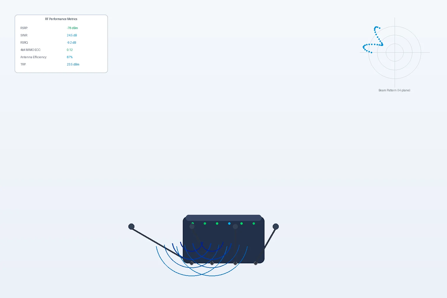
In the 5G CPE procurement process, antenna performance is often treated as an afterthought — a spec-sheet footnote overshadowed by throughput numbers, chipset brands, and software features. Yet antenna design and RF front-end engineering are arguably the single most important determinants of real-world CPE performance, particularly in the challenging deployment environments that define enterprise B2B use cases. A CPE with a best-in-class modem chipset paired with a poorly designed antenna system will consistently underperform a mid-range chipset with optimized RF engineering.
Why Antenna Design Matters More Than You Think
5G New Radio (NR) operates across a dramatically wider frequency range than any previous cellular generation — from 600 MHz (n71) to 47 GHz (n262 mmWave) and everything in between. Each frequency band presents fundamentally different propagation characteristics, antenna element requirements, and beamforming strategies. A CPE antenna system must simultaneously handle:
- Sub-1 GHz (FR1 low band): Excellent propagation through walls and obstacles, but requires larger antenna elements for efficient radiation. Critical for rural and suburban coverage where cell sites are distant.
- 1–6 GHz (FR1 mid band, including C-band n77/n78/n79): The “goldilocks” spectrum for 5G FWA — good capacity and reasonable propagation. Requires precisely tuned antenna elements with wide instantaneous bandwidth (up to 100 MHz per carrier for 5G NR).
- 24–47 GHz (FR2 mmWave): Massive capacity but extremely limited range and near-zero penetration through solid objects. Requires phased array antenna modules with dozens of individual elements and active beam-steering integrated circuits.
A CPE that excels on n78 C-band but underperforms on n71 low-band will fail at rural enterprise deployments. Conversely, a CPE without mmWave support may be inadequate for dense urban environments where carriers are densifying with mmWave small cells.
MIMO and Beamforming: The Multiplier Effect
Modern 5G CPE devices typically implement 4×4 MIMO (Multiple Input, Multiple Output) on sub-6 GHz bands — meaning four receive antennas and four transmit antennas operating simultaneously. This configuration can theoretically double spectral efficiency compared to 2×2 MIMO, but only if the antenna elements are sufficiently de-correlated. Achieving low correlation between four antenna elements in the confined space of a desktop CPE enclosure is a significant RF engineering challenge.
Key design considerations for 4×4 MIMO in CPE:
- Antenna element spacing: Minimum spacing of λ/2 (half-wavelength) between elements for adequate decorrelation. At 3.5 GHz (n78), λ/2 ≈ 43 mm — which begins to constrain the industrial design of compact CPE enclosures.
- Polarization diversity: Alternating between vertical and horizontal polarization, or using ±45° slant polarization, reduces correlation without increasing physical separation — effectively fitting more antennas into less space.
- Pattern diversity: Designing antenna elements with intentionally different radiation patterns (e.g., one broadside-facing element and one end-fire element) provides decorrelation through angular diversity rather than spatial separation.
- Mutual coupling compensation: When antenna elements are in close proximity, they couple electromagnetically — energy from one element induces currents in adjacent elements. Sophisticated matching networks and digital pre-distortion algorithms can compensate for mutual coupling effects, recovering the MIMO performance that would otherwise be lost.
For mmWave CPE, the challenge scales dramatically: phased array modules may contain 16, 32, or even 64 individual antenna elements per polarization, each with its own phase shifter and amplitude control. The antenna module becomes a complex, multi-layer PCB with integrated beamforming ICs — essentially a small radar system repurposed for communications.
External Antenna Ports: The Deployment Flexibility Multiplier
While integrated antennas work well for many deployment scenarios — particularly window-mounted CPE with clear line-of-sight to the serving cell — enterprise deployments frequently encounter challenging RF environments:
- CPE installed in basements, equipment rooms, or metal-clad buildings where internal antennas receive severely attenuated signals.
- Deployments in rural areas where the serving cell is 10+ km away and high-gain directional external antennas are necessary for a stable connection.
- Industrial environments with high electromagnetic interference from machinery, motors, and power equipment — where external antennas can be positioned away from noise sources.
Enterprise-grade 5G CPE should provide TS-9 or SMA external antenna ports with the following capabilities:
- Per-port configurability: The ability to assign specific antenna ports to specific frequency bands, enabling mixed configurations — for example, using integrated antennas for n78 mid-band while connecting high-gain directional external antennas for distant n71 low-band cell sites.
- Automatic antenna detection: The CPE should automatically sense when an external antenna is connected to a port and switch the RF path accordingly, without requiring manual configuration.
- External antenna vendor ecosystem: Published RF specifications (impedance, supported frequency ranges, maximum gain) that enable third-party antenna vendors to design compatible products, expanding deployment options for system integrators.
Signal Quality Metrics That Actually Matter
When evaluating CPE antenna performance, buyers should look beyond the marketing-friendly “antenna gain” number (typically quoted in dBi at a single frequency) and focus on metrics that predict real-world performance:
- Total Radiated Power (TRP): Measures the total power actually radiated by the CPE in all directions — a more meaningful metric than conducted transmit power, as it accounts for antenna efficiency.
- Total Isotropic Sensitivity (TIS): The reciprocal metric for receiver performance — the minimum signal level at which the CPE can maintain a connection, integrated over all spatial directions.
- Envelope Correlation Coefficient (ECC): Quantifies the independence of MIMO antenna elements. ECC < 0.3 is generally considered acceptable for 4×4 MIMO; ECC < 0.1 is excellent.
- Antenna efficiency: The ratio of radiated power to input power, expressed as a percentage or in dB. Even a 1 dB efficiency loss translates directly to reduced coverage range and lower throughput at the cell edge.
- In-band VSWR (Voltage Standing Wave Ratio): Measures impedance matching across the operating frequency band. Poor VSWR means reflected power that never reaches the antenna, wasted as heat in the transmitter.
Real-World RF Engineering Tradeoffs
CPE antenna design is an exercise in managing competing constraints. Industrial design wants a sleek, compact enclosure; RF engineering needs physical volume for antenna separation. Marketing wants to quote the highest possible antenna gain; real-world deployments need wide beamwidth for consistent coverage regardless of device orientation. Cost optimization pushes for integrated antennas only; deployment flexibility demands external ports.
The best 5G CPE designs navigate these tradeoffs thoughtfully, optimizing for real-world performance rather than spec-sheet hero numbers. For B2B buyers, the practical advice is simple: evaluate CPE antenna performance in your actual deployment environment, with your actual carrier network, during your actual usage patterns. A CPE that delivers 2 Gbps in a lab on a test network is less valuable than one that delivers a consistent 500 Mbps in a basement equipment room at a real customer site.
Antenna engineering may not be glamorous, but in the physics of radio communications, it is everything. Choose accordingly.
Honlly Telecom’s 5G CPE products feature precision-engineered multi-band antenna systems with 4×4 MIMO, external antenna port options, and carrier-optimized RF front-end designs. Contact our engineering team for detailed RF performance data and deployment consultation.