Category: Blog

Technical guides and best practices

  • A Technical Buyer’s Guide to 5G CPE Zero-Trust Security Architecture: Hardware Root of Trust, Secure Boot, and End-to-End Encryption for Enterprise FWA Deployments

    A Technical Buyer’s Guide to 5G CPE Zero-Trust Security Architecture: Hardware Root of Trust, Secure Boot, and End-to-End Encryption for Enterprise FWA Deployments

    As enterprise 5G fixed wireless access deployments scale from proof-of-concept trials to production networks carrying sensitive corporate, financial, and operational traffic, the security architecture of CPE devices has emerged as a boardroom-level concern. The traditional perimeter-based security model—where CPE was treated as a trusted endpoint inside the corporate firewall—is fundamentally incompatible with the distributed, multi-site, cloud-first enterprise architectures dominating 2026. For technical buyers evaluating 5G CPE for enterprise and industrial deployments, zero-trust security principles must now inform procurement specifications as rigorously as throughput, latency, and radio performance parameters.

    The CPE Attack Surface: Why 5G FWA Demands Zero-Trust

    5G CPE occupies a uniquely exposed position in the enterprise network topology. Unlike a core router locked in a climate-controlled data center with physical access controls and 24/7 security monitoring, CPE is frequently deployed in branch offices, retail locations, construction trailers, and outdoor enclosures—environments where physical tampering, unauthorized access, and network-based attacks are realistic threat vectors. Compromised CPE provides an attacker with a persistent foothold inside the enterprise WAN, with the ability to intercept, modify, or exfiltrate traffic across every connected LAN segment.

    The 3GPP 5G security architecture (TS 33.501) provides robust air interface protection through 5G AKA mutual authentication, SUCI-based subscriber identity privacy, and 256-bit encryption on the radio link. However, these protections terminate at the CPE’s modem interface. Post-modem—within the CPE’s application processor, operating system, LAN interfaces, and management plane—enterprise security depends entirely on the CPE’s embedded security architecture, which varies dramatically across vendors and price points.

    Hardware Root of Trust: The Foundational Layer

    Zero-trust CPE security begins at the silicon level. A hardware root of trust (HRoT) provides an immutable, cryptographically verifiable foundation that ensures the CPE boots only authentic, vendor-signed firmware and that device identity keys cannot be extracted or cloned even with physical access to the device.

    Secure Boot Chain: The CPE’s boot ROM, signed by the SoC vendor’s root key, cryptographically verifies the first-stage bootloader. Each subsequent stage—U-Boot or LK bootloader, Linux kernel, root filesystem—is verified against signed hashes before execution. Any modification to the boot chain, whether through firmware tampering, JTAG/SWD debug interface exploitation, or storage replacement, causes boot failure and, ideally, tamper-evident logging to a secure element. Enterprise procurement specifications should mandate secure boot with hardware-backed key storage (e.g., TPM 2.0 or platform-integrated secure enclave) and configurable security policy for boot verification failure behavior.

    Trusted Platform Module (TPM) Integration: A discrete or firmware TPM 2.0 implementation enables secure storage of device identity keys, measured boot attestation, and sealed storage that binds encryption keys to specific platform configuration register (PCR) values. For enterprise zero-trust architectures, TPM-backed device attestation allows the network’s policy enforcement point to cryptographically verify that the CPE is running authorized firmware and configuration before granting network access—a foundational zero-trust principle.

    Secure Element and SIM/eUICC Integration

    The CPE’s UICC or eUICC provides a tamper-resistant secure element for 5G network authentication, but its security capabilities can and should be leveraged for CPE device identity beyond the 3GPP authentication framework. The GSMA’s IoT SAFE (IoT SIM Applet For Secure End-to-End) initiative standardizes the use of the SIM/eSIM as a hardware security module for device-level TLS client certificates, credential storage, and cryptographic operations.

    CPE implementing IoT SAFE can use the carrier-provisioned eUICC as the hardware root for mutually authenticated TLS connections to enterprise zero-trust policy engines, cloud management platforms, and ZTNA (Zero Trust Network Access) brokers. This eliminates the need for separate hardware security modules and leverages the existing mobile operator security infrastructure—including secure OTA provisioning and key rotation—for enterprise CPE identity management.

    End-to-End Encryption and Traffic Isolation

    Zero-trust architecture mandates that no traffic is trusted based on network location alone. For 5G CPE deployed at the enterprise edge, this translates to mandatory encryption across the CPE’s entire data path:

    IPsec and WireGuard Tunnel Termination: Enterprise CPE must support hardware-accelerated IPsec (IKEv2 with strong cipher suites) and WireGuard for tunnel termination to enterprise VPN concentrators or cloud security gateways. AES-256-GCM and ChaCha20-Poly1305 cipher support with hardware crypto acceleration is essential for maintaining multi-gigabit throughput with encryption overhead. CPE should support per-VLAN tunnel mapping, enabling different traffic classes (corporate data, guest Wi-Fi, IoT telemetry) to be encrypted and routed through separate security domains.

    Micro-Segmentation at the CPE Edge: Advanced enterprise CPE implements 802.1Q VLAN trunking with per-VLAN security policies, enabling micro-segmentation between corporate workstations, payment systems, building management IoT, and guest networks directly at the branch edge. Combined with dynamic policy enforcement from a cloud-based zero-trust policy engine, this architecture ensures that a compromised IoT sensor cannot pivot to attack the payment processing VLAN—even when both connect through the same 5G CPE.

    MACsec and 802.1X for LAN-Side Security: For deployments where the CPE’s LAN ports connect to managed switches or other infrastructure devices, MACsec (IEEE 802.1AE) at line rate and 802.1X supplicant functionality on the CPE’s LAN interfaces provide link-layer encryption and port-based authentication that extend the zero-trust boundary one hop deeper into the enterprise network.

    Management Plane Security: The Overlooked Vector

    CPE management interfaces—TR-069/TR-369 (USP), SNMP, SSH, RESTCONF, and vendor-specific cloud management APIs—represent a high-value attack surface. Zero-trust CPE security architecture must protect these interfaces with the same rigor applied to the data plane:

    Mutual TLS for Management Protocols: All CPE management protocols must use mutually authenticated TLS 1.3 with client certificate authentication. The CPE must authenticate the management server (preventing man-in-the-middle attacks), and the management server must authenticate the CPE (preventing rogue device registration). Certificate enrollment should use EST (RFC 7030) or SCEP with hardware-backed key generation in the TPM or secure element.

    Role-Based Access Control and Audit Logging: CPE must implement granular RBAC distinguishing between firmware update, configuration change, monitoring-only, and diagnostic roles. All administrative actions must generate syslog or structured audit events with immutable timestamps, forwarded to a centralized SIEM. Local admin credentials must be salted and hashed with modern algorithms (bcrypt, Argon2id), never stored in plaintext or reversible formats.

    Secure OTA Firmware Updates: Over-the-air firmware updates are the most security-critical operation in the CPE lifecycle. Updates must be signed with vendor private keys, verified by the CPE before installation, and delivered over mutually authenticated TLS. The update mechanism must support A/B partition schemes with automatic rollback on verification failure, and update metadata (version, hash, signature, target hardware revision) must be independently verifiable by enterprise security teams.

    Building the Procurement Specification

    For technical buyers drafting 5G CPE procurement specifications in 2026, the following zero-trust security requirements should be considered mandatory for enterprise-grade deployments:

    • Hardware root of trust with immutable boot ROM and secure boot chain verification
    • TPM 2.0 or equivalent secure enclave for key storage and device attestation
    • GSMA IoT SAFE or equivalent SIM-based credential storage for device identity
    • Hardware-accelerated IPsec (AES-256-GCM) and WireGuard with per-VLAN tunnel mapping
    • Mutual TLS 1.3 for all management interfaces with hardware-backed client certificates
    • Signed, verified OTA firmware updates with A/B dual-bank fallback
    • Granular RBAC with immutable audit logging to external SIEM
    • 802.1X supplicant and MACsec support for LAN-side zero-trust extension
    • FIPS 140-3 or Common Criteria EAL4+ certification for cryptographic modules

    The enterprise 5G FWA security landscape in 2026 demands that CPE be treated not as a simple modem-and-router appliance, but as a security-enforcement point at the distributed enterprise edge. Organizations that apply zero-trust principles to CPE procurement will build 5G FWA networks that are scalable, defensible, and audit-ready—while those that treat CPE security as an afterthought will embed technical debt that becomes exponentially more expensive to remediate as deployments scale.

  • A Technical Buyer’s Guide to 5G CPE IPv6 Transition: Dual-Stack Architecture, IPv6-Only Deployment Strategies, and Carrier-Grade NAT64/DNS64 Design

    A Technical Buyer’s Guide to 5G CPE IPv6 Transition: Dual-Stack Architecture, IPv6-Only Deployment Strategies, and Carrier-Grade NAT64/DNS64 Design

    As global IPv4 address exhaustion enters its terminal phase—with RIPE NCC, APNIC, and ARIN all operating from final /8 allocations and IPv4 transfer market prices exceeding USD 55 per address—the transition to IPv6 in 5G fixed wireless access deployments has moved from a future-proofing exercise to an operational imperative. For technical buyers evaluating 5G CPE for carrier and enterprise deployments in 2026, understanding IPv6 transition architecture is no longer optional: it directly impacts address scalability, application performance, NAT traversal overhead, and total cost of ownership across the CPE lifecycle.

    The IPv4 Exhaustion Landscape and 5G FWA Implications

    5G FWA networks introduce a unique scaling challenge for IPv4. Unlike traditional mobile broadband where NAT44 and CGNAT at the mobile core suffice for smartphone traffic, FWA CPE serves entire LANs—often with dozens to hundreds of connected devices per premises—each expecting routable or at least well-NATed IP connectivity. CGNAT at the 5G core introduces stateful translation overhead that scales linearly with concurrent sessions, creating throughput bottlenecks, increased latency, and application compatibility issues for protocols that embed IP addresses in payloads (SIP, FTP, IPsec, gaming protocols).

    The 3GPP 5G architecture mandates IPv6 support in the 5G core (5GC), and all major 5G standalone (SA) deployments globally operate with IPv6-native user plane functions (UPF). However, the last-mile CPE—where enterprise LANs meet the 5G WAN—remains the critical decision point where IPv6 transition strategy is implemented or broken.

    Dual-Stack Architecture: The Pragmatic Baseline

    Dual-stack remains the most widely deployed IPv6 transition mechanism in 5G CPE, and for good reason: it provides simultaneous IPv4 and IPv6 connectivity without requiring either protocol to tunnel through the other. In a dual-stack 5G FWA deployment, the 5GC assigns both an IPv4 address (typically RFC 1918 private address behind CGNAT) and an IPv6 global unicast address (GUA) prefix to the CPE WAN interface. The CPE then distributes IPv4 via NAT44 on the LAN side and IPv6 via prefix delegation (DHCPv6-PD) or SLAAC.

    Key design considerations for dual-stack CPE:

    DHCPv6 Prefix Delegation: The CPE must request an IPv6 prefix from the 5GC via DHCPv6-PD, with typical prefix lengths ranging from /56 to /64 depending on operator policy. Enterprise-grade CPE should support configurable prefix delegation hint sizes and sub-delegation to downstream routers for multi-subnet deployments.

    DNS64/NAT64 Integration: Even in dual-stack deployments, the 5GC may implement DNS64/NAT64 for IPv6-only transport, requiring the CPE to correctly handle synthesized AAAA records (RFC 7050) and ensure applications that use literal IPv4 addresses are properly translated through the NAT64 gateway’s well-known prefix (64:ff9b::/96).

    Happy Eyeballs v2 (RFC 8305): CPE should not interfere with client-side Happy Eyeballs algorithm operation, ensuring that dual-stack endpoints can rapidly prefer IPv6 when available while falling back to IPv4 seamlessly. Enterprise deployments should validate CPE firmware does not introduce DNS filtering or connection tracking that biases protocol selection.

    IPv6-Only Deployments: The End-State Architecture

    Forward-looking operators and large enterprises are increasingly targeting IPv6-only CPE deployments, eliminating IPv4 from the access network entirely. In this model, the CPE receives only an IPv6 GUA on its WAN interface, and IPv4 connectivity for legacy applications is provided through NAT64 translation at the 5GC UPF or through a CLAT (Customer-side Translator) function integrated into the CPE itself.

    464XLAT (RFC 6877): This architecture combines a CLAT function in the CPE that performs stateless IPv4-to-IPv6 translation (SIIT) with a PLAT (Provider-side Translator) in the operator network that performs stateful NAT64. The CPE’s CLAT function intercepts IPv4 traffic from LAN devices, encapsulates it in IPv6 packets addressed to the PLAT’s NAT64 prefix, and the PLAT completes the translation to public IPv4. This architecture is particularly suited to mobile network operators with large-scale CGNAT infrastructure already in place.

    MAP-T and MAP-E (RFC 7597, 7599): Mapping of Address and Port (MAP) technologies provide deterministic, stateless IPv4-over-IPv6 translation that eliminates the stateful NAT bottleneck at the operator core. MAP-T (Translation mode) and MAP-E (Encapsulation mode) are gaining traction in Asian operator deployments where CGNAT capacity planning has become a significant operational concern. CPE supporting MAP must implement Border Relay (BR) client functionality with configurable mapping rules, port-set allocation, and correct handling of ICMP/PMTUD in the translated path.

    Enterprise Considerations: Beyond Protocol Support

    IPsec and VPN Compatibility: Enterprise CPE commonly terminate IPsec tunnels to headquarters or cloud VPN concentrators. IPv6 transition mechanisms must be validated for IPsec interoperability: IKEv2’s support for IPv6 transport and IPv6-embedded IPsec Security Associations must be confirmed across CPE firmware versions. ESP encapsulation in MAP-E, in particular, can introduce MTU issues requiring careful PMTUD or MSS clamping configuration.

    SD-WAN Integration: Many enterprise 5G FWA deployments position the CPE as a WAN edge device within a broader SD-WAN fabric. The CPE’s IPv6 transition mechanism must be compatible with SD-WAN overlay protocols (VXLAN, GRE, IPsec) that may themselves operate over IPv4 or IPv6 underlay networks. Dual-stack CPE provides the greatest SD-WAN deployment flexibility, while 464XLAT and MAP-T/E architectures may require overlay-to-underlay address family translation in the SD-WAN edge.

    Application Performance Monitoring: IPv6 transition adds protocol translation hops that can complicate performance monitoring and root-cause analysis. Enterprise-grade CPE should expose per-protocol (IPv4/IPv6) throughput, latency, and session count metrics via SNMP, NETCONF/YANG, or RESTCONF APIs, enabling network operations teams to separately monitor native and translated traffic paths.

    Evolving Standards and the Road Ahead

    The IETF v6ops working group continues to refine IPv6 transition operational guidance, with RFC 9099 (Operational Security Considerations for IPv6 Networks) and RFC 9386 (IPv6 Deployment Status) providing updated recommendations relevant to CPE design. The Broadband Forum’s TR-124 issue 8 introduces IPv6 transition requirements for 5G residential gateways, specifying mandatory CLAT and 464XLAT support alongside dual-stack and IPv6-only operational modes.

    For technical buyers, the key takeaway is clear: 5G CPE procurement specifications must explicitly define IPv6 transition architecture requirements, including preferred mechanism (dual-stack, 464XLAT, MAP-T/E), required prefix delegation behavior, DNS64/NAT64 handling, and VPN/SD-WAN compatibility. CPE that ships with only IPv4 CGNAT support in 2026 is already technically obsolete for any operator or enterprise with a five-year deployment horizon.

  • A Technical Buyer’s Guide to 5G CPE Thermal Management: Passive Cooling, Industrial-Grade Enclosures, and Outdoor Deployment Reliability

    A Technical Buyer’s Guide to 5G CPE Thermal Management: Passive Cooling, Industrial-Grade Enclosures, and Outdoor Deployment Reliability

    Thermal management is one of the most overlooked yet critical design disciplines in 5G CPE engineering. While buyers and operators focus on throughput, band support, and MIMO configuration, the thermal envelope directly determines a device’s sustained performance, outdoor survivability, and total cost of ownership across a multi-year deployment lifecycle. A CPE that throttles under load or fails prematurely due to heat stress undermines the entire FWA business case.

    This guide provides a structured framework for technical buyers, procurement managers, and operator engineering teams evaluating 5G CPE thermal design — from passive cooling strategies to industrial-grade enclosure certification.

    Why Thermal Design Matters for 5G CPE

    5G CPE devices operate under fundamentally different thermal constraints than their 4G predecessors. Several factors contribute to increased heat generation:

    Higher Power Amplifier Output. 5G NR, particularly in n77/n78 (3.5 GHz) and n258/n257 (mmWave) bands, requires power amplifiers operating at higher output levels to maintain link budget. Each dB of PA output translates to additional milliwatts of dissipated heat.

    Multi-Band Carrier Aggregation. Modern CPE devices simultaneously operate across multiple frequency bands — sub-6 GHz for coverage and mmWave or mid-band for capacity. Each active RF chain contributes to the total thermal load.

    Integrated Wi-Fi 6/6E/7 AP. CPE serving as a combined 5G modem and Wi-Fi access point runs two high-performance radios in a single enclosure, essentially doubling the thermal challenge.

    Edge Compute Workloads. As CPE devices incorporate AI/ML inference for intelligent traffic steering, predictive maintenance, and local analytics, the SoC runs sustained compute workloads that compound RF-induced heat generation.

    The result: a 5G CPE can generate 12–25W of thermal dissipation load in sustained operation, compared to 5–10W for a typical 4G CPE. Without adequate thermal management, device temperature can exceed safe operating limits within 15–30 minutes of sustained full-load operation.

    Passive Cooling: The First Line of Defense

    For most CPE form factors — particularly indoor desktop and wall-mounted units — passive cooling is the preferred thermal management strategy. It eliminates fan-related failure modes, acoustic noise, and dust ingress, all of which are unacceptable in residential and quiet office environments.

    Heat Sink Design

    Effective passive cooling starts with the heat sink. Key design parameters include:

    Material Selection: Die-cast aluminum is the industry standard, balancing thermal conductivity (~120–170 W/m·K for common alloys), weight, and manufacturing cost. Premium designs may specify copper inserts for hotspot mitigation at the modem/SoC interface. – Fin Geometry: Fin height, pitch, and orientation must be optimized for the device’s mounting orientation. Wall-mounted CPE benefits from vertically oriented fins that enhance natural convection. Desktop CPE with horizontal orientation requires forced airflow paths or chimney-effect enclosures. – Surface Area: As a rule of thumb, passive cooling requires approximately 30–50 cm² of effective surface area per watt of dissipated heat for a 40°C ambient-to-junction temperature delta. A 20W CPE thus needs 600–1,000 cm² of effective heat sink surface area.

    Thermal Interface Materials (TIM)

    The gap between the modem/SoC die and the heat sink is a critical thermal bottleneck. High-performance thermal pads or phase-change materials with conductivity above 5 W/m·K are recommended. Gap filler pads must account for component height variance across the PCB — a 0.2mm tolerance stack can increase thermal resistance by 30% if uncompensated.

    Enclosure as Heat Sink

    Advanced passive designs use the entire CPE enclosure as a thermal dissipation surface. Magnesium-alloy or aluminum chassis bonded to internal heat spreaders distribute heat across the full device surface, eliminating hotspots while maximizing radiative and convective cooling. This approach is particularly effective for slim, wall-mounted indoor CPE where aesthetic constraints limit visible heat sink protrusions.

    Outdoor CPE: The Industrial-Grade Challenge

    Outdoor CPE — deployed on rooftops, poles, or building exteriors — faces thermal conditions that passive cooling alone cannot always handle. These devices must operate reliably across an ambient temperature range of -40°C to +55°C, with direct solar radiation adding 15–25°C of effective thermal load during peak sun exposure.

    IP-Rated Enclosures with Thermal Management

    The ingress protection (IP) rating fundamentally constrains thermal design. An IP67 or IP68 enclosure is sealed against dust and water — which also means zero natural airflow. Every watt of heat must be conducted through the enclosure walls. This creates a design tension between environmental sealing and thermal dissipation that requires careful engineering:

    Dual-Chamber Architecture: Some outdoor CPE designs separate the sealed electronics chamber from a vented heat exchanger chamber with Gore-Tex membranes that allow pressure equalization and limited vapor transmission without compromising IP rating. – Die-Cast Enclosure with Integrated Fins: The enclosure itself becomes the primary heat sink. Thick-walled die-cast aluminum bodies with external fins maximize surface area while maintaining structural integrity and IP compliance. – Solar Radiation Mitigation: Light-colored or reflective enclosure finishes reduce solar absorption. A white or light-gray powder-coated surface can reduce solar gain by 40–60% compared to dark-colored or bare metal enclosures.

    Sun Shield and Mounting Considerations

    Outdoor CPE mounting accessories contribute significantly to thermal performance:

    – A sun shield or visor above the CPE enclosure blocks direct solar radiation during peak hours, reducing internal temperature rise by 10–15°C. – Pole-mount brackets should include a thermal standoff gap (minimum 10mm) between the enclosure and the mounting surface to maintain convection airflow on all sides. – Orientation matters: vertical mounting with fins aligned to the prevailing wind direction improves cooling by up to 25% compared to horizontal orientations.

    Active Cooling: When Fans Are Necessary

    In extreme thermal environments — high ambient temperature combined with sustained full-load operation — passive cooling may be insufficient. Active fan-based cooling introduces moving parts but can dramatically increase heat dissipation capacity.

    Fan Selection and Reliability

    For CPE applications, fan selection criteria differ from consumer electronics:

    MTBF (Mean Time Between Failures): Industrial-grade fans rated for 70,000–100,000 hours at 40°C are minimum requirements for operator-grade outdoor CPE. Consumer-grade fans (30,000–50,000 hours) are unacceptable for multi-year outdoor deployments. – Dual-Ball vs. Sleeve Bearings: Dual-ball bearing fans maintain performance across wide temperature ranges and tolerate mounting in any orientation. Sleeve-bearing fans degrade rapidly when mounted vertically and are not recommended for outdoor CPE. – Fan Speed Control: PWM-controlled, temperature-regulated fan curves balance cooling with acoustic noise and power consumption. A smart fan controller can reduce fan duty cycle below 20% during idle/low-load conditions, extending fan life and reducing dust accumulation.

    Hybrid Passive-Active Designs

    The optimal approach for demanding outdoor deployments is a hybrid design: passive cooling handles normal operation, and a temperature-controlled fan activates only when the internal junction temperature exceeds a threshold (typically 65–70°C). This minimizes fan runtime — often to less than 5% of total operating hours in temperate climates — while providing thermal headroom for extreme conditions.

    Thermal Testing and Validation Standards

    Technical buyers should verify that CPE vendors have subjected their designs to rigorous thermal validation:

    IEC 60068-2 Environmental Testing: Thermal cycling (-40°C to +85°C, minimum 100 cycles), damp heat (85°C/85% RH, 1,000 hours), and thermal shock testing. – Soak Testing: Sustained operation at maximum ambient temperature (typically +55°C) with full RF and compute load for a minimum of 72 continuous hours with zero throttling events. – Solar Load Simulation: IEC 60068-2-5 procedures for solar radiation testing, simulating 1,120 W/m² irradiance.

    Evaluation Checklist for Buyers

    When assessing 5G CPE thermal design, request the following from vendors:

    1. Thermal simulation reports showing junction temperatures for CPU, modem, PA, and Wi-Fi chipset under worst-case conditions (max ambient + full load).
    2. Throttling policy documentation: At what temperature does the device begin reducing TX power, MIMO layers, or carrier aggregation? What is the recovery behavior?
    3. Enclosure material and finish specifications, including solar absorptivity index for outdoor models.
    4. IP rating certification from an accredited test laboratory — not self-declared.
    5. Fan MTBF certification and fan replacement procedures if active cooling is used.
    6. Field failure data from comparable deployments in similar climate zones.

    The Bottom Line

    Thermal management is not a secondary concern — it is a first-order determinant of CPE reliability and operator satisfaction. A device that handles heat well will deliver consistent throughput, survive harsh outdoor environments, and minimize field replacement costs over a 5–7 year deployment lifetime. At Honlly Telecom, our 5G CPE designs incorporate industrial-grade passive cooling architectures, IP67-rated enclosures, and hybrid thermal solutions validated to the most demanding operator specifications. Contact our engineering team to discuss thermal requirements for your next FWA deployment.

  • A Technical Buyer’s Guide to 5G CPE Carrier Aggregation and Spectrum Sharing: Multi-Band Optimization, DSS Strategies, and Throughput Maximization for Operator Deployments

    A Technical Buyer’s Guide to 5G CPE Carrier Aggregation and Spectrum Sharing: Multi-Band Optimization, DSS Strategies, and Throughput Maximization for Operator Deployments

    Carrier aggregation (CA) is the engine that transforms 5G from a single-band connectivity solution into a multi-gigabit wireless broadband platform. For operators deploying Fixed Wireless Access at scale, the CPE’s CA capabilities directly determine peak and average throughput, cell-edge performance, and the efficient utilization of fragmented spectrum assets. This guide provides a structured evaluation framework for technical buyers assessing 5G CPE carrier aggregation architecture, Dynamic Spectrum Sharing (DSS) integration, and real-world throughput optimization strategies.

    The Carrier Aggregation Landscape in 5G NR

    5G NR carrier aggregation differs fundamentally from LTE CA in both scale and flexibility. Release 15 introduced a baseline of up to 16 component carriers (CCs) with a maximum aggregated bandwidth of approximately 1 GHz in Frequency Range 2 (FR2, mmWave). Release 16 and 17 expanded intra-band and inter-band CA combinations, while Release 18 (5G-Advanced) introduces enhanced cross-carrier scheduling and AI-assisted carrier selection.

    Current CA Configurations Relevant to FWA CPE

    For sub-6 GHz FWA deployments, the most commercially relevant CA configurations include:

    | Configuration | Component Carriers | Aggregate BW | Peak DL Throughput (4×4 MIMO) | |—————|——————-|————-|——————————-| | n77 + n78 Intra-band | 2–4 CCs | 200–400 MHz | 3.4–6.8 Gbps | | n77 + n78 + n79 | 3–6 CCs | 300–600 MHz | 5.1–10.2 Gbps | | n1 + n3 + n78 | 3 CCs | 110–190 MHz | 1.9–3.2 Gbps | | n28 + n78 (Low+Mid) | 2 CCs | 130–170 MHz | 2.2–2.9 Gbps | | n258 + n257 (mmWave) | 4–8 CCs | 400–800 MHz | 6.8–13.6 Gbps |

    The practical throughput numbers depend on modulation order (256QAM vs. 64QAM), MIMO layers, and coding rate. Buyers should request vendor-validated throughput figures at specific signal conditions rather than relying on theoretical peak rates.

    Inter-Band vs. Intra-Band CA: Architecture Trade-offs

    Intra-Band Contiguous CA

    When an operator holds contiguous spectrum within a single band (e.g., 100 MHz + 60 MHz within n78), intra-band contiguous CA is the simplest configuration. A single RF chain and power amplifier can cover the entire bandwidth, minimizing component count, cost, and power consumption. CPE supporting intra-band contiguous CA typically achieves the highest power efficiency and lowest cost-per-Mbps.

    Intra-Band Non-Contiguous CA

    Non-contiguous intra-band CA addresses the common scenario where an operator’s spectrum within a band is fragmented — for example, 80 MHz + 40 MHz separated by a 20 MHz gap held by another operator. This requires a wider RF front-end or dual receive paths within the same band, increasing component complexity but enabling aggregation of otherwise stranded spectrum assets.

    Inter-Band CA

    Inter-band CA combines carriers across different frequency bands — most commonly low-band (n28, 700 MHz for coverage) with mid-band (n78, 3.5 GHz for capacity). This configuration requires multiple RF chains, separate antennas or a wideband antenna array, and more sophisticated baseband processing for cross-band scheduling. The value is significant: low-band carriers provide reliable control-plane coverage and uplink performance, while mid-band carriers deliver downlink throughput.

    For FWA CPE deployed in suburban and rural environments, inter-band CA combining sub-1 GHz coverage bands with 3.5 GHz capacity bands is often the most impactful configuration for balancing reach and speed.

    Dynamic Spectrum Sharing (DSS)

    DSS enables operators to simultaneously operate LTE and 5G NR in the same frequency band by dynamically allocating resource blocks between the two technologies on a millisecond timescale. For CPE buyers, DSS support is particularly relevant in markets where operators are refarming 4G spectrum for 5G rather than deploying on greenfield spectrum.

    How DSS Affects CPE Design

    From the CPE perspective, DSS is largely transparent at the physical layer — the device receives scheduling grants and demodulates the allocated resource blocks regardless of whether adjacent blocks carry LTE or NR traffic. However, two CPE features significantly impact DSS performance:

    1. DSS-Aware Rate Matching: The CPE modem must correctly interpret LTE Cell-Specific Reference Signal (CRS) rate matching patterns from the gNB to avoid demodulation errors on resource elements shared with LTE. CPE chipsets with DSS-optimized baseband processing achieve 5–15% higher throughput in DSS scenarios compared to basic implementations.

    2. MBSFN Subframe Awareness: In DSS deployments where LTE uses MBSFN subframes to free resources for NR, the CPE must handle the dynamic subframe configuration changes without connection drops. Field testing has shown that some early 5G CPE implementations experience intermittent connectivity in aggressive DSS configurations — buyers should verify DSS interoperability with their specific operator’s LTE/NR resource allocation scheme.

    CA Combination Validation: What Buyers Must Verify

    Not all CA combinations listed in modem datasheets are commercially viable. 3GPP specifications define hundreds of possible CA combinations, but practical implementation is constrained by:

    RF Front-End Complexity. Each additional CC adds filters, LNAs, and switching networks. A CPE supporting 6-way CA may require 12+ discrete RF filters, each adding insertion loss, cost, and PCB area. The gap between “chipset-capable” and “product-implemented” CA combinations can be significant.

    Coexistence and Desense. Multiple simultaneously active receivers operating across wide frequency separations (e.g., n28 at 700 MHz and n78 at 3.5 GHz) risk self-interference from harmonics, intermodulation products, and local oscillator leakage. Effective RF shielding, PCB isolation, and filtering are essential but add cost and physical volume.

    Antenna Isolation. Multiple antenna elements supporting different bands require sufficient isolation to avoid coupling. For FWA CPE with integrated antennas, achieving >15 dB of inter-band isolation in a compact form factor is a significant RF engineering challenge.

    Power and Thermal Budget. Each additional active receive path adds 0.5–2W to the power budget. CPE designs that claim extensive CA support on paper may throttle CA combinations under thermal load. Buyers should request sustained throughput data (not peak burst rates) at maximum ambient temperature.

    Buyer Verification Protocol

    When evaluating a CPE’s CA claims, request:

    1. A complete CA combination list with per-combination validated throughput (not chipset theoretical maximums).
    2. Sustained throughput stability data — 24-hour throughput logs at maximum CA configuration, with zero throttling events.
    3. Band-specific RSSI-to-throughput mapping showing performance degradation curves as signal strength decreases.
    4. DSS interoperability test reports with the target operator’s specific NR/LTE resource allocation configuration.
    5. Thermal performance at maximum CA configuration — junction temperatures and any throttling triggers.

    CA and Spectrum Strategy: Aligning CPE with Operator Roadmaps

    Operators should evaluate CPE CA capabilities against their mid-term spectrum strategy (3–5 year horizon), not just the current spectrum portfolio. Key considerations:

    Refarming Timelines

    If an operator plans to refarm 3G (2100 MHz) or 4G (1800 MHz, 2600 MHz) spectrum for 5G NR within the CPE deployment lifecycle, the device must support those band additions. CPE with software-defined radio (SDR) architectures offer future-proofing advantages — new bands can be added via firmware update rather than hardware replacement.

    5G-Advanced CA Enhancements

    Release 18 introduces several CA-related enhancements that will arrive in CPE chipsets from late 2026:

    Cross-Carrier Scheduling with Single DCI: Reducing control channel overhead by scheduling multiple carriers with a single downlink control information message. – AI/ML-Based Carrier Selection: Network-side AI models predict optimal carrier combinations per-UE based on load, interference, and mobility patterns. – Supplementary Uplink (SUL) Enhancements: Aggregating low-band uplink with mid-band downlink to improve uplink coverage in time-division duplex (TDD) deployments, critical for video conferencing and cloud upload use cases.

    Buyers procuring CPE for 2027–2028 deployments should prioritize Release 18-capable platforms to capture these efficiency gains.

    Cost vs. CA Capability: Finding the Right Tier

    Not every FWA deployment requires maximum CA. Segmenting CPE specifications by use case optimizes procurement cost:

    | Deployment Tier | Recommended CA | Target Throughput | Typical Cost Delta | |—————-|—————-|——————-|——————-| | Entry / Rural | 2× CA (Low+Mid) | 100–300 Mbps | Baseline | | Standard Suburban | 3–4× CA (Mid-band) | 500 Mbps–1 Gbps | +15–25% | | Premium Urban | 4–6× CA (Mid+mmWave) | 1–3 Gbps | +35–60% | | Enterprise / SMB | 6–8× CA (Full FR1+FR2) | 3–10 Gbps | +60–120% |

    The cost deltas include RF front-end, antenna, thermal, and baseband processing overhead. For operators serving diverse geographic markets, a tiered CPE portfolio — rather than a single “maximum CA” SKU — typically delivers the best ROI.

    Practical Throughput Expectations

    Buyers should calibrate expectations around real-world throughput. In field conditions, even well-designed CA implementations deliver 50–70% of theoretical peak rates due to:

    – Signal-to-Noise Ratio (SNR) degradation at cell edge – Network loading (shared spectrum among multiple UEs) – Backhaul constraints at the gNB – Transport-layer overhead (UDP/TCP headers, retransmissions) – Wi-Fi bridging losses for CPE operating as an AP

    A CPE rated for 5 Gbps peak CA throughput should be expected to deliver 2–3.5 Gbps in typical suburban deployment conditions and 1–2 Gbps at the cell edge. These are still transformative speeds for FWA — enabling multi-user 4K streaming, cloud gaming, and business-grade VPN performance — but realistic expectations prevent deployment disappointments.

    Conclusion

    Carrier aggregation is the defining performance feature of 5G FWA CPE. The difference between a well-executed CA architecture and a checklist-driven implementation can be a 2× gap in real-world throughput, coverage, and operator satisfaction. Technical buyers should move beyond counting component carriers and rigorously evaluate sustained performance, thermal behavior, DSS interoperability, and alignment with operator spectrum roadmaps.

    At Honlly Telecom, our 5G CPE portfolio spans entry-level 2× CA devices to premium 8× CA multi-gigabit platforms, all validated through extensive field testing with Tier-1 operators across Asia, Europe, and the Middle East. Contact our product team for detailed CA combination lists, throughput validation reports, and deployment case studies tailored to your spectrum environment.

  • A Technical Buyer’s Guide to 5G NR RedCap CPE: Optimized Device Design for Mid-Tier IoT, Industrial Sensors, and Massive-Scale Deployments

    A Technical Buyer’s Guide to 5G NR RedCap CPE: Optimized Device Design for Mid-Tier IoT, Industrial Sensors, and Massive-Scale Deployments

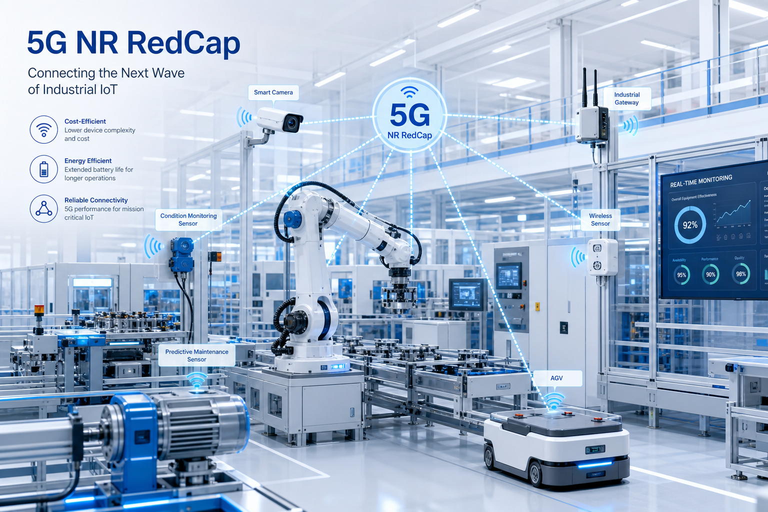
    As 5G networks mature beyond flagship smartphones and high-performance FWA, the ecosystem is turning its attention to a vast middle ground of use cases that require more than LTE-M or NB-IoT can deliver, yet do not justify the cost and complexity of full-specification 5G NR devices. Enter 5G NR RedCap (Reduced Capability), standardized in 3GPP Release 17 and enhanced in Release 18, which defines a device class optimized for mid-tier IoT, industrial wireless sensors, surveillance cameras, and wearable ecosystems. This guide provides technical buyers with a detailed framework for evaluating RedCap CPE and terminal solutions.

    What 5G NR RedCap Actually Reduces—and What It Preserves

    RedCap is not simply “5G-lite.” It is a carefully engineered device simplification that targets a specific performance envelope while preserving core 5G NR capabilities that differentiate it from LTE-based IoT technologies. The key reductions relative to full-spec NR devices (FR1) include:

    • Reduced Bandwidth: Maximum 20 MHz in FR1 (vs. 100 MHz for full NR), with mandatory support for 5 MHz and optional 10 MHz configurations. This simplification reduces RF front-end complexity, ADC/DAC requirements, and baseband processing demands significantly.
    • Reduced Antenna Configuration: 1 Rx or 2 Rx branches (vs. mandatory 4 Rx for full NR FR1). For many industrial sensor and wearable applications, 1 Rx is sufficient, though 2 Rx is recommended for FWA-type RedCap CPE to support basic receive diversity.
    • Half-Duplex FDD Support: Optional half-duplex FDD operation, eliminating the need for duplex filters and further reducing component count and cost for devices that can tolerate non-simultaneous transmission and reception.
    • Relaxed Processing Timeline: Extended processing timelines that reduce baseband computational requirements, enabling lower-cost modem silicon without compromising reliability.

    Critically, RedCap preserves: 5G NR waveform and numerology (OFDM with flexible subcarrier spacing); network slicing support (URSP); 5G core network integration; 5G security architecture (SUPI concealment, 5G-AKA, EAP-AKA’); and positioning enhancements. These retained capabilities mean RedCap devices are first-class citizens on the 5G network, not a separate IoT overlay.

    RedCap vs. eRedCap: The Release 18 Expansion

    3GPP Release 18 introduced “eRedCap” (enhanced RedCap), which further narrows the device complexity gap toward LTE Cat-1/Cat-4 territory while remaining within the 5G NR framework. eRedCap targets peak data rates of approximately 10 Mbps—similar to LTE Cat-1 bis but with 5G-native network integration benefits.

    Key eRedCap features include: mandatory 5 MHz bandwidth support (10 MHz maximum, 5 MHz minimum for FR1); further reduced peak data rates through transport block size limitations and relaxed MIMO layer counts; and optional support for device-specific bandwidth part (BWP) configurations that allow the network to schedule RedCap devices within a narrower portion of the carrier bandwidth while full NR devices use the entire carrier.

    For CPE and terminal buyers, the RedCap/eRedCap continuum creates a device hierarchy that maps cleanly to specific use cases: standard RedCap for fixed wireless sensors, industrial cameras, and gateways requiring 50–150 Mbps; eRedCap for wearable devices, asset trackers, and environmental sensors needing 5–10 Mbps with minimal power consumption and lowest possible BOM cost.

    RedCap CPE Architecture: System Design Considerations

    Designing a RedCap CPE or terminal requires a fundamentally different approach than downsizing a full-spec 5G CPE. The optimizations are architectural, not merely subtractive:

    Modem Selection: The Qualcomm Snapdragon X35 5G Modem-RF system, announced in early 2023 and now shipping in volume, was purpose-built for RedCap rather than derived from a full NR platform. Competing solutions from MediaTek (T300 series) and UNISOC are also reaching production maturity. Purpose-built RedCap modems offer 40–60% lower power consumption and 30–50% smaller PCB footprint compared to full NR modems configured in reduced mode.

    RF Front-End Simplification: The 20 MHz bandwidth limit means the RF front-end can use narrower-band LNAs and PAs with relaxed linearity requirements, surface acoustic wave (SAW) filters instead of bulk acoustic wave (BAW) filters in many bands, and simplified antenna switch modules. This contributes to a BOM cost reduction of approximately 35–50% compared to full-spec 5G CPE RF front-ends.

    Power Architecture: RedCap devices targeting battery-powered or energy-harvesting operation can leverage 3GPP Release 17 power-saving enhancements including: extended Discontinuous Reception (eDRX) with significantly longer sleep cycles than LTE-M; Radio Resource Management (RRM) relaxation for stationary devices to reduce measurement overhead; and Paging Early Indication (PEI) to skip unnecessary PDCCH monitoring.

    Thermal Design: Lower baseband processing complexity and reduced RF power translate to approximately 50–70% lower thermal output compared to full NR CPE, enabling fanless, sealed industrial enclosures suitable for harsh outdoor and factory-floor environments where active cooling is prohibited.

    Use Case Deep Dive: Industrial Wireless Sensor Networks

    One of the most compelling RedCap CPE applications is as an aggregation gateway for industrial wireless sensor networks in smart manufacturing environments. In this architecture, a RedCap CPE serves as the 5G backhaul endpoint for an on-premise sensor mesh (e.g., IO-Link Wireless, WirelessHART, or proprietary ISM-band sensor protocols), providing a managed bridge between the factory sensor layer and the 5G core network.

    The RedCap CPE in this role requires: industrial protocol conversion capability (Modbus TCP, PROFINET, EtherNet/IP to 5G data plane); deterministic latency guarantees via 5G network slicing and TSN (Time-Sensitive Networking) integration; ruggedized IP65 or higher enclosure with M12 connectors for industrial power and Ethernet; and support for IEEE 802.1CB Frame Replication and Elimination for Reliability (FRER) for ultra-reliable low-latency applications.

    The economic case is compelling: a RedCap-based sensor gateway at approximately 40% of the cost of a full-spec 5G industrial CPE, with sufficient throughput for aggregating hundreds of sensor streams at typical industrial data rates of 1–10 Mbps total backhaul traffic.

    Procurement Considerations for RedCap CPE

    Technical buyers evaluating RedCap 5G CPE should address the following decision points:

    • Band Support: Confirm RedCap band support aligns with deployment regions. While full NR devices support dozens of bands, RedCap devices typically support a targeted subset (Bands n1, n3, n5, n7, n8, n28, n38, n40, n41, n77, n78, n79). Verify specific band combinations with carrier aggregation support if required for throughput targets.
    • Rx Diversity: For fixed wireless sensor gateways with challenging RF environments (basements, metal enclosures, factory floors), specify minimum 2 Rx for basic receive diversity. Single Rx configurations are acceptable for outdoor pole-mounted units with line-of-sight to the cell site.
    • Network Slicing: URSP (UE Route Selection Policy) support is mandatory for industrial RedCap CPE to ensure traffic separation between critical control plane data and bulk telemetry. Verify the modem and device firmware support URSP rules with at least 8 concurrent PDU session support.
    • Positioning: For asset tracking and logistics applications, verify support for 5G NR positioning methods (DL-TDOA, UL-TDOA, Multi-RTT) available in Release 17/18, with sub-meter accuracy targets for indoor deployments.
    • Certification Roadmap: RedCap device certification through GCF/PTCRB is still maturing. Confirm that target operator(s) have completed RedCap network feature verification and that the device vendor has a clear certification timeline with committed conformance test coverage.
    • eRedCap Migration Path: For deployments planning volume scaling over 3–5 years, evaluate whether the CPE platform supports a pin-compatible upgrade to eRedCap modems as the technology matures and use cases evolve toward lower data rates and power consumption profiles.

    Market Outlook and Ecosystem Maturity

    The RedCap ecosystem is crossing the chasm from early-adopter trials to commercial scale in H2 2026. Operator support has expanded rapidly: China Mobile, China Telecom, and China Unicom have all completed RedCap commercial network verification and launched RedCap-specific data plans; AT&T and T-Mobile US are conducting enterprise trials with industrial and logistics customers; and major European operators including Deutsche Telekom, Vodafone, and BT/EE have activated RedCap on a portion of their 5G SA networks.

    ABI Research forecasts that RedCap/eRedCap device shipments will reach 85 million units annually by 2028, with industrial IoT and fixed wireless sensor gateways representing the largest single segment at approximately 40% of volume. The CPE and terminal segment within RedCap is projected to grow from approximately 1.2 million units in 2026 to over 8 million units by 2029.

    For procurement organizations planning mid-tier IoT and industrial connectivity strategies, 2026 H2 represents the inflection point where RedCap CPE transitions from technology evaluation to deployment-ready procurement. The devices shipping today are purpose-built, carrier-certified, and economically viable—the key remaining question is ecosystem scale, not technical readiness.

  • A Technical Buyer’s Guide to 5G CPE eSIM and Multi-IMSI Architecture: Remote SIM Provisioning, Profile Management, and Operator Flexibility

    A Technical Buyer’s Guide to 5G CPE eSIM and Multi-IMSI Architecture: Remote SIM Provisioning, Profile Management, and Operator Flexibility

    As 5G FWA deployments scale across multiple operators and geographies, the SIM architecture embedded within CPE devices has evolved from a simple authentication token into a strategic enabler of deployment flexibility, operational efficiency, and long-term lifecycle management. This technical buyer’s guide examines the eSIM and Multi-IMSI architectures now being integrated into enterprise-grade 5G CPE platforms, providing procurement teams with the technical framework needed to evaluate solutions for multi-operator, multi-region, and future-proof FWA deployments.

    The Evolution from Physical SIM to eSIM in CPE

    Traditional 5G CPE devices relied on removable UICC (Universal Integrated Circuit Card) formats—typically 2FF (Mini-SIM) or 4FF (Nano-SIM) physical cards. While functional, this approach introduced significant operational friction: truck rolls for SIM swaps during operator changes, physical SIM inventory management across distribution channels, vulnerability to theft and tampering, and limited ability to dynamically re-provision connectivity profiles in response to network conditions or commercial agreements.

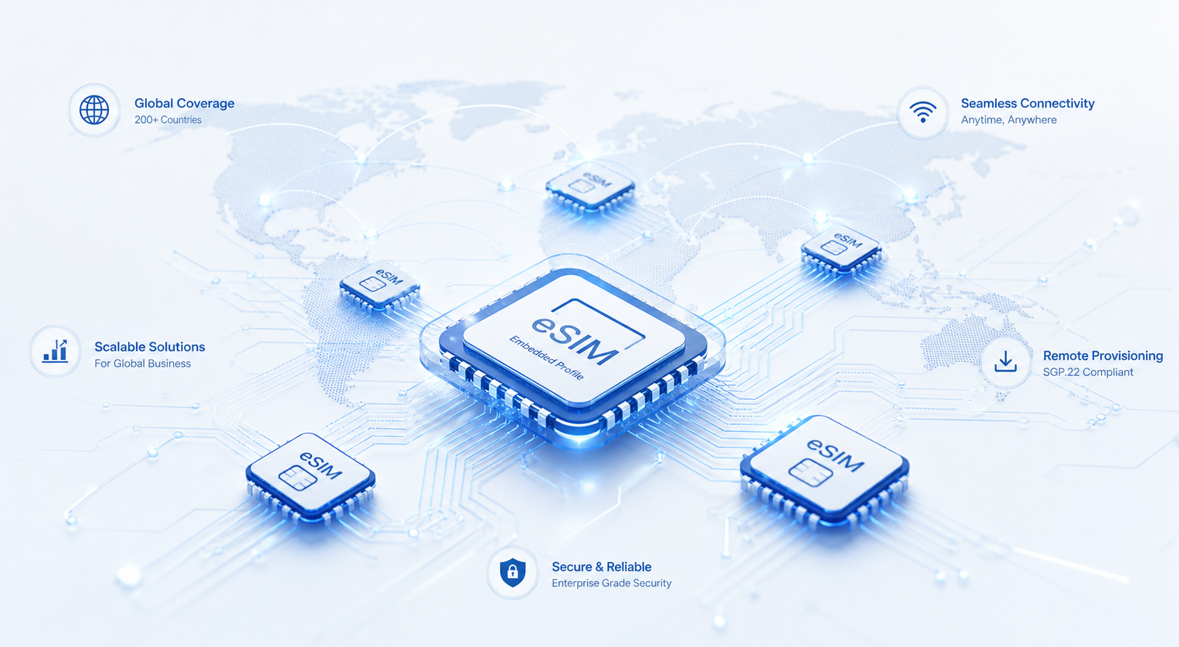
    The GSMA’s eSIM specifications—particularly GSMA SGP.02 (M2M) and SGP.22 (Consumer) architectures—have matured to address these pain points for CPE deployments. An eSIM (embedded UICC or eUICC) is a soldered, non-removable SIM chip that supports remote SIM provisioning (RSP), enabling operators to download, enable, disable, and delete operator profiles over-the-air without physical access to the device.

    The SGP.22 Consumer architecture, originally designed for smartphones and wearables, has proven particularly suitable for 5G CPE. It supports a “pull” model where the device initiates profile download via an SM-DP+ (Subscription Manager – Data Preparation+) server, activated through a QR code or activation code delivered via the operator’s mobile app or web portal. This consumer-friendly activation flow is increasingly adopted for residential FWA CPE, enabling self-install and zero-touch provisioning.

    For enterprise and industrial CPE deployments, the SGP.02 M2M architecture offers a “push” model where profiles are provisioned remotely by the operator via an SM-DP (Subscription Manager – Data Preparation) server, with minimal end-user interaction. This architecture supports bulk provisioning, scheduled profile switching, and integration with operator OSS/BSS systems—critical capabilities for deployments with thousands of distributed CPE endpoints.

    Multi-IMSI Architecture: Operational Flexibility for Roaming and Multi-Operator Deployments

    While eSIM enables remote profile management, Multi-IMSI (Multiple International Mobile Subscriber Identity) architecture extends the concept by allowing a single device to hold multiple active operator profiles simultaneously, with intelligent switching logic that selects the optimal profile based on configurable policies.

    A Multi-IMSI 5G CPE typically integrates a eUICC with support for multiple IMSI/applet combinations, managed through a SIM applet framework running on the UICC’s Java Card platform. The device maintains several operator profiles—each containing its own IMSI, authentication keys (Ki), OPC, and network parameters—with an applet that monitors network availability and switches active profiles based on rules such as:

    • Geographic Location: Automatically select the home network profile when on the home PLMN, switch to a roaming partner profile when abroad to achieve local-rate data pricing
    • Network Quality: Switch to an alternate operator profile if the primary network’s signal quality or throughput falls below defined thresholds
    • Time-Based Scheduling: Use a specific operator profile during business hours for guaranteed SLA performance, switch to a lower-cost profile outside peak hours
    • Application-Based Steering: Route critical enterprise traffic through one operator while offloading bulk data to another

    This Multi-IMSI capability is particularly valuable for: cross-border deployments where a single CPE model must operate across multiple countries; maritime and logistics applications where vessels and containers traverse multiple territorial waters; and enterprise branch offices requiring redundant WAN connectivity with automatic failover between operators.

    GSMA eSIM Compliance and Certification Considerations

    Procurement teams evaluating eSIM-enabled 5G CPE should verify compliance with the relevant GSMA specifications based on deployment use case:

    • SGP.02 v4.2: M2M eSIM architecture with push-based provisioning; required for enterprise/industrial CPE managed through operator OSS/BSS platforms
    • SGP.22 v3.0: Consumer eSIM architecture with pull-based provisioning; suitable for residential and SOHO CPE with end-user self-activation
    • SGP.32 v1.0: IoT eSIM specification; increasingly relevant for massive IoT deployments with constrained devices and LPWA connectivity

    GSMA SAS (Security Accreditation Scheme) certification for the eUICC manufacturer and SM-DP+ provider is essential. SAS-UP (UICC Production) certifies the secure manufacturing and personalization process for eUICCs, while SAS-SM (Subscription Management) certifies the security of the RSP platform infrastructure. Devices integrating non-certified eSIM components face interoperability risks and potential operator rejection during certification.

    Security Architecture: Mutual Authentication and Profile Isolation

    The eSIM security model builds on the proven 3GPP AKA (Authentication and Key Agreement) framework while adding eUICC-specific protections. Key security considerations include:

    ISD-R (Issuer Security Domain – Root): The root security domain on the eUICC, managed by the eUICC manufacturer (EUM), responsible for creating and managing ISD-Ps (Issuer Security Domain – Profiles). The ISD-R private key never leaves the eUICC secure element, ensuring that only authorized entities can manage profiles.

    Profile Interlock and Isolation: Each operator profile operates within its own ISD-P, providing cryptographic isolation between profiles. One operator’s profile cannot access another’s credentials or network parameters. This is critical for scenarios where the CPE may switch between competing operators.

    CI (Certificate Issuer) Trust Chain: GSMA’s Certificate Issuer root of trust ensures that only authenticated SM-DP+ servers can communicate with the eUICC for profile operations. Buyers should confirm that the eUICC vendor participates in the GSMA CI program and supports the latest ECC (Elliptic Curve Cryptography) key algorithms in addition to legacy RSA.

    Integration with 5G CPE Platform Architecture

    From a system integration perspective, the eSIM/Multi-IMSI subsystem must interface with several CPE platform components:

    • Modem Baseband: The modem must support eUICC ISO 7816 interface or SPI-based eUICC connections, with modem firmware capable of hot-swapping IMSI/applet sessions without requiring a full modem reset—a non-trivial requirement that varies significantly between modem vendors
    • Device Management Client: Integration with TR-369 USP or LwM2M device management agents to enable remote profile management operations through standardized APIs, including profile enable/disable, profile list query, and profile download initiation
    • Local Management UI/API: A web GUI or mobile app interface for end-users or field technicians to initiate profile downloads (e.g., scan a QR code), view active profile information, and manage basic eSIM settings

    Procurement Checklist for eSIM/Multi-IMSI 5G CPE

    When evaluating 5G CPE solutions with eSIM and Multi-IMSI capabilities, technical buyers should verify the following specifications:

    • eUICC compliance: GSMA SGP.02 and/or SGP.22 certified, with SAS-UP accreditation
    • Number of simultaneously stored operator profiles: minimum 3 profiles for Multi-IMSI use cases; 5+ preferred for global deployments
    • Profile switching time: target under 30 seconds for seamless failover; modem vendors’ support for hot-swap without full baseband re-initialization should be confirmed
    • RSP platform interoperability: verified against major SM-DP+ providers (IDEMIA, G+D, Thales, Kigen, Valid) used by target operators
    • Fallback physical SIM slot: dual-SIM architecture with one eSIM and one physical SIM slot provides maximum deployment flexibility during eSIM ecosystem transition periods
    • Remote management API compliance: TR-369 USP or equivalent for operator-managed profile operations
    • Security certification: CC EAL4+ or higher for eUICC secure element; GSMA SAS-SM for the RSP infrastructure

    The transition to eSIM and Multi-IMSI architectures in 5G CPE represents a foundational shift in how connectivity is provisioned, managed, and monetized. For operators and enterprises deploying FWA at scale, selecting the right SIM architecture today will determine deployment agility, operational cost structure, and vendor flexibility for years to come.

  • A Technical Buyer’s Guide to 5G CPE Network Timing and Synchronization: IEEE 1588v2 Precision Time Protocol, Synchronous Ethernet, and GNSS-Disciplined Oscillator Design for TDD FWA Networks

    A Technical Buyer’s Guide to 5G CPE Network Timing and Synchronization: IEEE 1588v2 Precision Time Protocol, Synchronous Ethernet, and GNSS-Disciplined Oscillator Design for TDD FWA Networks

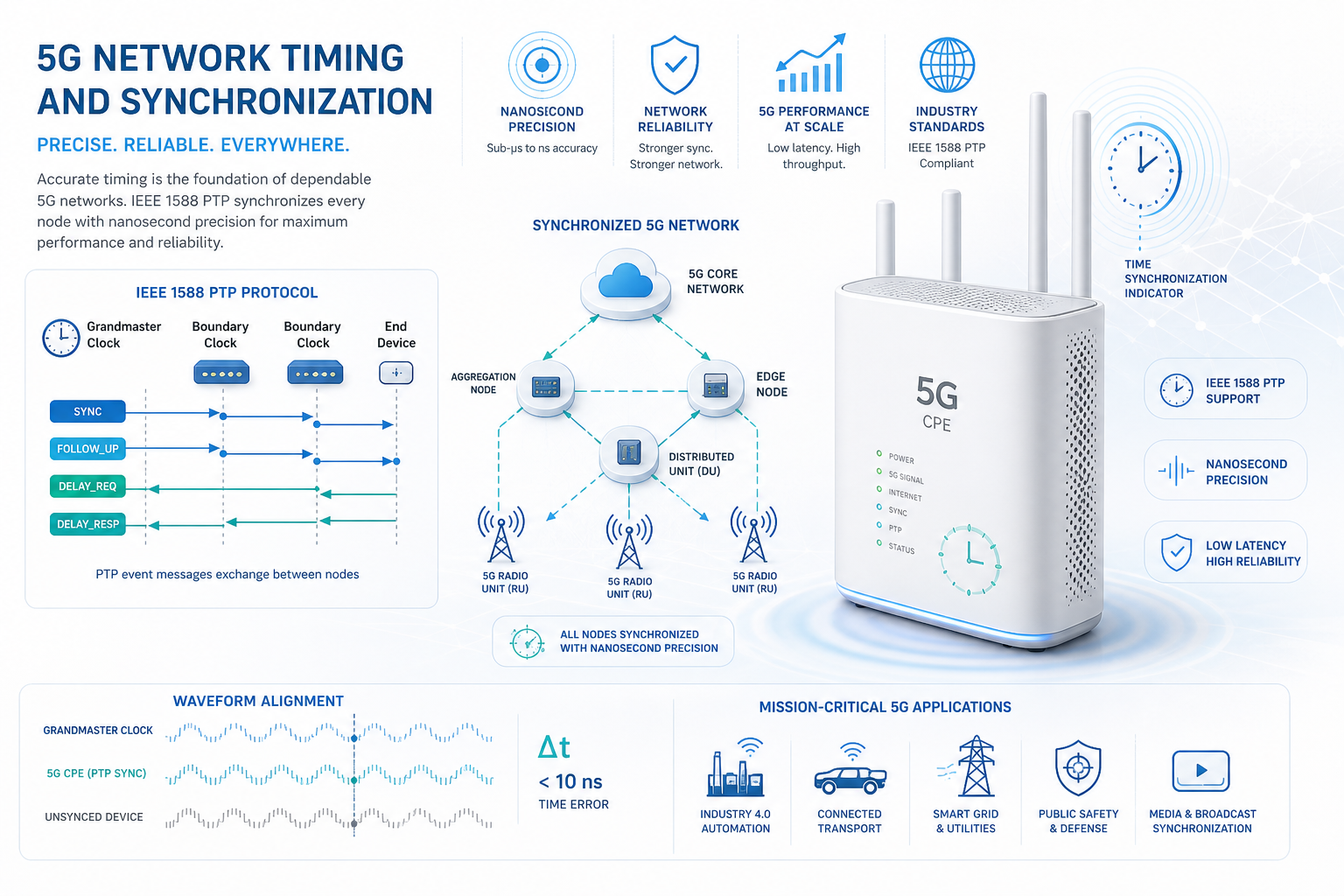
    Network timing and synchronization is one of the most underappreciated yet critical aspects of 5G CPE design and procurement. In Time Division Duplex (TDD) networks — which constitute the vast majority of global 5G NR deployments — all base stations and connected CPE devices must maintain tightly synchronized time alignment to avoid inter-symbol interference, guard period violations, and catastrophic cross-link interference. For technical buyers evaluating 5G CPE for carrier-grade FWA deployments, understanding the synchronization architecture inside the device is essential to ensuring reliable operation, regulatory compliance, and future-proof network integration.

    Why Timing Matters in 5G TDD CPE

    5G NR TDD networks operate on a shared frequency channel where uplink and downlink transmissions are separated in time rather than frequency. This requires all devices in a given cell — base stations and CPE alike — to agree on a common time reference with microsecond-level precision. The 3GPP TS 38.133 specification defines stringent timing requirements for CPE devices, including:

    • Cell phase synchronization accuracy: ±1.5 µs relative to the serving cell’s phase reference for wide-area base stations (Category A).
    • Transmit timing adjustment: CPE must adjust its uplink transmission timing based on Timing Advance (TA) commands from the gNB with step sizes of 0.52 µs for FR1 and sub-carrier spacing-dependent granularity for FR2.
    • Frequency accuracy: ±0.1 ppm for wide-area base stations and ±0.2 ppm for local-area/home base stations over a 1 ms observation period.
    • Holdover performance: In the event of GNSS signal loss, the CPE’s internal oscillator must maintain timing accuracy within 1.5 µs for at least 24 hours (ITU-T G.8272 PRTC Class B requirement).

    Failure to meet these requirements results in degraded network performance — increased block error rate (BLER), reduced spectral efficiency, and in severe cases, complete service disruption as interfering uplink transmissions bleed into adjacent downlink slots. For operators managing tens of thousands of CPE devices across a TDD network, timing synchronization is not optional; it is foundational.

    IEEE 1588v2 Precision Time Protocol (PTP) in 5G CPE

    IEEE 1588v2 Precision Time Protocol has emerged as the primary packet-based synchronization mechanism for 5G transport networks and is increasingly implemented at the CPE level. In a 5G FWA architecture, PTP operates in the telecom profile defined by ITU-T G.8275.1 (full timing support) and G.8275.2 (partial timing support), delivering sub-microsecond synchronization accuracy over packet-switched backhaul networks.

    Key PTP implementation considerations for CPE buyers include:

    PTP Profile Support

    Enterprise and carrier-grade CPE should support both G.8275.1 (multicast PTP over Ethernet with boundary clock functionality at each network hop) and G.8275.2 (unicast PTP with assistance information, designed for networks where not every intermediate node is PTP-aware). The ability to operate as an ordinary clock (OC) in G.8275.1 mode or as a PTP telecom slave clock (T-TSC) in G.8275.2 mode provides deployment flexibility across different operator network architectures.

    Hardware Timestamping

    Software-based PTP implementations introduce jitter on the order of tens to hundreds of microseconds, which is unacceptable for 5G TDD synchronization. CPE devices must implement hardware timestamping at the Ethernet PHY or MAC layer to achieve the required nanosecond-level precision. Look for devices explicitly documenting IEEE 1588v2 hardware timestamping support in their chipset specifications — typically implemented in the Ethernet switch or PHY silicon rather than in software on the application processor.

    One-Step vs. Two-Step Clock Modes

    One-step clocks embed the egress timestamp directly into the Sync message as it departs, reducing protocol overhead and improving accuracy at high message rates. Two-step clocks send the timestamp in a separate Follow_Up message. While two-step is more common in existing deployments, one-step mode is preferred for 5G CPE due to reduced processing latency and simpler implementation in Transparent Clock (TC) network elements.

    Message Rates and Announce Intervals

    Standard PTP Sync message rates for telecom applications range from 16 to 128 messages per second. Higher rates improve timing accuracy at the cost of increased CPU and network overhead. CPE should support configurable message rates to match operator-specific network engineering guidelines. The Announce interval (typically 1–2 seconds) determines how frequently the PTP grandmaster identity and clock quality are communicated, affecting failover behavior in redundant grandmaster deployments.

    Synchronous Ethernet (SyncE): Frequency Synchronization at the Physical Layer

    Synchronous Ethernet (SyncE), standardized in ITU-T G.8261, G.8262, and G.8264, provides physical-layer frequency synchronization by recovering a precision clock from the Ethernet line signal — analogous to how traditional SDH/SONET networks distribute timing. In 5G CPE, SyncE serves as a complementary mechanism to PTP, providing highly stable frequency synchronization that enhances PTP phase accuracy and extends holdover performance.

    For technical evaluation, CPE SyncE capability should include:

    • G.8262 Synchronous Ethernet Equipment Clock (EEC) compliance: Option 1 (EEC-Option 1) for 2048 kbit/s hierarchy or Option 2 (EEC-Option 2) for 1544 kbit/s hierarchy, supporting wander generation, tolerance, and transfer specifications.
    • Ethernet Synchronization Messaging Channel (ESMC): G.8264-defined protocol for communicating Synchronization Status Messages (SSM) that convey clock quality levels (QL) across the SyncE chain, enabling automatic clock selection and protection switching.
    • Hybrid SyncE + PTP operation: The ability to use SyncE for frequency distribution while PTP handles phase/time alignment, combining the best attributes of each technology. This hybrid mode is increasingly specified in operator RFPs for dense urban FWA deployments where GNSS signal availability is compromised.

    GNSS-Disciplined Oscillator Design

    For outdoor CPE and enterprise-grade gateways, an integrated GNSS receiver with a disciplined oscillator provides an autonomous time and frequency reference independent of network-based synchronization. This is particularly valuable in TDD networks where GNSS serves as the Primary Reference Time Clock (PRTC) per ITU-T G.8272.

    Key GNSS subsystem evaluation criteria:

    Multi-Constellation Support

    Modern CPE should support at least GPS (L1 C/A) and one or more additional constellations — GLONASS (L1), BeiDou (B1I), or Galileo (E1) — to improve satellite visibility, time-to-first-fix (TTFF), and resilience against single-constellation outages. Multi-band support (L1/L2 or L1/L5) further improves accuracy by enabling ionospheric error correction, though it increases BOM cost and power consumption.

    Oscillator Types and Holdover Performance

    The oscillator technology directly determines GNSS holdover capability:

    • TCXO (Temperature-Compensated Crystal Oscillator): Basic holdover of 1–10 µs over 4–8 hours. Suitable for indoor CPE where GNSS is not the primary timing source. Cost: low.
    • OCXO (Oven-Controlled Crystal Oscillator): Holdover of 1.5 µs over 24–72 hours, meeting PRTC Class B requirements. The industry standard for outdoor CPE and carrier-grade FWA devices. Cost: moderate.
    • Miniature Atomic Clock (MAC) / Chip-Scale Atomic Clock (CSAC): Holdover of 1 µs over 7+ days. Emerging technology for mission-critical and remote deployments. Cost: high, but decreasing as manufacturing scales.

    For most operator FWA deployments, an OCXO-based GNSS-disciplined oscillator provides the optimal balance of performance, cost, and power consumption. Buyers should verify that the CPE’s holdover specification is validated against ITU-T G.8272 PRTC Class B requirements under temperature cycling (−20°C to +60°C), as laboratory bench measurements at constant temperature do not represent field conditions.

    GNSS Antenna Considerations

    Outdoor CPE must include a dedicated GNSS antenna port (typically SMA or N-type connector) supporting active antennas with 3–5 V DC bias and 20–40 dB gain. The antenna should provide right-hand circular polarization (RHCP) with an axial ratio below 3 dB for reliable multi-constellation reception. For installations in urban canyons or high-rise environments, the CPE should support multi-path mitigation algorithms and advanced signal processing to maintain timing lock under degraded sky-view conditions.

    Practical Procurement: Evaluation Checklist

    When evaluating 5G CPE for TDD FWA deployments, technical buyers should assess the following synchronization capabilities:

    1. PTP Profile Compliance: Does the device support ITU-T G.8275.1 and/or G.8275.2 profiles with hardware timestamping?
    2. SyncE Support: Is G.8262 EEC compliance documented, with ESMC for automatic clock quality negotiation?
    3. GNSS Multi-Constellation: Which constellations are supported? Multi-band capability available?
    4. Oscillator Type: TCXO, OCXO, or atomic? What is the validated holdover specification under temperature cycling?
    5. Hybrid Operation: Does the device support simultaneous SyncE + PTP + GNSS with automatic failover hierarchy?
    6. 3GPP Timing Compliance: Are TS 38.133 phase accuracy, frequency accuracy, and timing advance requirements documented in device conformance test reports?
    7. Management and Monitoring: Can PTP clock status, GNSS satellite visibility, and oscillator health be monitored via TR-369 USP, SNMP, or vendor API?
    8. GNSS Antenna Port: Is a dedicated, bias-tee-powered antenna connector provided? What is the supported antenna gain range?

    Future Directions: Enhanced Synchronization for 5G-Advanced and 6G

    As networks evolve toward 5G-Advanced (3GPP Release 18/19) and early 6G research, synchronization requirements will tighten further. Key developments on the horizon include:

    • Sub-100 ns accuracy: Coordinated Multi-Point (CoMP) transmission, massive MIMO reciprocity-based beamforming, and carrier aggregation across non-co-located cells will require timing accuracy below 100 nanoseconds — an order of magnitude tighter than current 5G NR requirements.
    • Network-Integrated Sensing: 6G’s vision of joint communication and sensing (JCAS) requires picosecond-level synchronization for accurate range, velocity, and angle estimation — likely necessitating optical or atomic timing references at the network edge.
    • AI-Assisted Timing Recovery: Machine learning algorithms for predictive oscillator drift compensation, multi-path GNSS signal processing, and adaptive PTP clock servo optimization are emerging as techniques to improve timing resilience without escalating hardware costs.

    For CPE procurement with a 5–7 year deployment horizon, selecting devices with OCXO-based synchronization and field-upgradable timing firmware provides headroom for these evolving requirements without requiring hardware replacement.

    Frequently Asked Questions

    Why is network timing critical for 5G TDD CPE?

    5G TDD networks share a single frequency channel for uplink and downlink, separated in time. All devices must maintain microsecond-level time alignment to prevent inter-symbol interference and cross-link interference. 3GPP TS 38.133 specifies phase accuracy within ±1.5 µs for wide-area deployments.

    What is the difference between PTP and SyncE for CPE synchronization?

    PTP (IEEE 1588v2) provides both time/phase and frequency synchronization via packet-based messaging, achieving sub-microsecond accuracy with hardware timestamping. SyncE (G.8262) provides only frequency synchronization at the physical layer by recovering a clock from the Ethernet line signal. They are complementary: SyncE provides stable frequency reference that enhances PTP phase accuracy.

    What oscillator type is recommended for outdoor 5G FWA CPE?

    OCXO (Oven-Controlled Crystal Oscillator) is the industry standard for outdoor CPE, providing holdover of 1.5 µs over 24–72 hours per ITU-T G.8272 PRTC Class B requirements. TCXO is acceptable for indoor CPE without GNSS dependency, while chip-scale atomic clocks are emerging for mission-critical remote deployments.

    Does 5G CPE need GNSS if the network provides PTP synchronization?

    GNSS provides an independent, autonomous timing reference that serves as a backup when network PTP is degraded and as a PRTC source for the wider synchronization architecture. Hybrid operation combining GNSS, PTP, and SyncE with automatic failover is recommended for carrier-grade 5G FWA CPE deployments.

    Need 5G CPE with carrier-grade synchronization for your TDD FWA network? Contact Honlly Telecom to discuss your timing requirements. Our engineering team can provide detailed IEEE 1588v2 PTP, SyncE, and GNSS-disciplined oscillator specifications for our outdoor and enterprise CPE product lines.

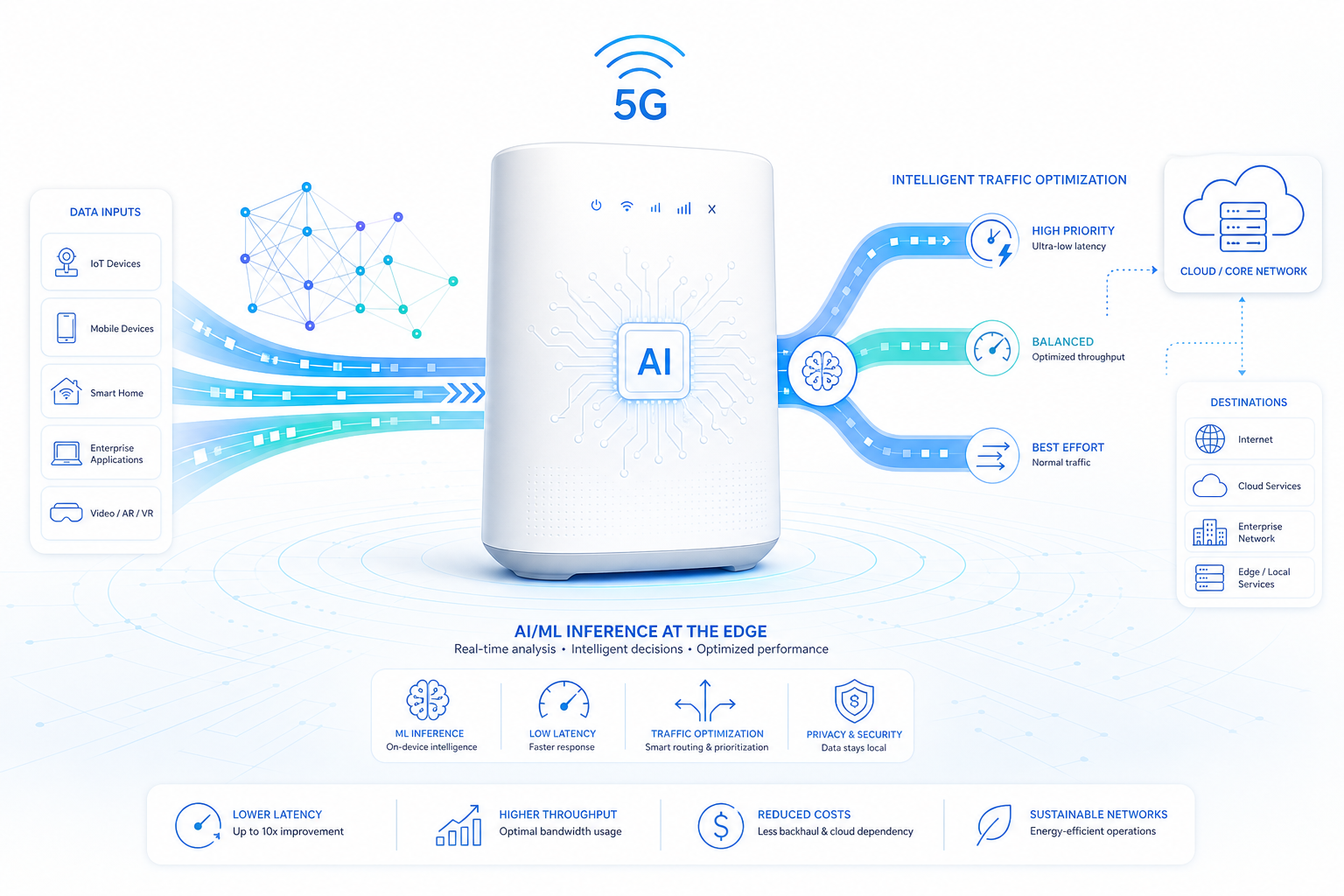
  • A Technical Buyer’s Guide to 5G CPE AI/ML Inference at the Edge: On-Device Neural Processing Engines for Intelligent Traffic Steering, Predictive Fault Detection, and Autonomous Network Optimization

    A Technical Buyer’s Guide to 5G CPE AI/ML Inference at the Edge: On-Device Neural Processing Engines for Intelligent Traffic Steering, Predictive Fault Detection, and Autonomous Network Optimization

    The integration of artificial intelligence and machine learning (AI/ML) inference capabilities directly into 5G CPE silicon represents one of the most significant architectural shifts in fixed wireless access device design since the transition from 4G to 5G. As 5G-Advanced (3GPP Release 18) formally introduces AI/ML framework support into the 3GPP specification, CPE devices are evolving from passive connectivity endpoints into intelligent network nodes capable of on-device traffic analysis, autonomous optimization, and predictive maintenance — all without requiring cloud round-trips. For technical buyers and network engineering teams evaluating next-generation 5G CPE, understanding the AI/ML hardware and software capabilities inside the device is rapidly becoming as important as evaluating RF performance or throughput benchmarks.

    The Architectural Case for On-Device AI in 5G CPE

    Why move AI inference to the CPE rather than centralizing it in the operator’s cloud or core network? The answer lies in the confluence of three technical and economic factors:

    1. Latency Constraints

    Many AI-driven optimizations — such as real-time traffic steering decisions, instantaneous interference detection, and millisecond-scale QoS adjustments — cannot tolerate the 30–100 ms round-trip latency introduced by cloud-based inference. On-device AI enables sub-millisecond inference latency, making it viable for time-sensitive networking decisions that directly impact user quality of experience (QoE).

    2. Bandwidth and Cost Efficiency

    Transmitting raw telemetry data, packet capture samples, and RF spectrum snapshots from thousands of CPE devices to a centralized analytics platform consumes significant backhaul bandwidth and cloud compute resources. On-device inference reduces data transmission to only actionable insights, anomalies, and aggregated statistics — cutting telemetry bandwidth requirements by 80–95% in typical deployments.

    3. Privacy and Data Sovereignty

    Enterprise customers and regulated industries increasingly require that traffic metadata, usage patterns, and network topology information remain on-premises. On-device AI ensures that sensitive data never leaves the CPE, addressing GDPR, CCPA, and industry-specific data residency requirements while still enabling intelligent network optimization.

    Neural Processing Hardware in 5G CPE Silicon

    The AI/ML capabilities of a 5G CPE are fundamentally determined by the inference hardware integrated into its System-on-Chip (SoC). Three categories of AI acceleration hardware are currently found in 5G CPE platforms:

    Dedicated Neural Processing Units (NPUs)

    Purpose-built AI accelerators designed for efficient inference of deep neural network models. Modern 5G modem platforms now integrate NPUs directly alongside the CPU, DSP, and modem subsystems:

    • Qualcomm® Hexagon™ NPU: Integrated in Snapdragon X80 and X75 modem-RF platforms, delivering up to 40 TOPS (INT8) for on-device inference. Supports TensorFlow Lite, ONNX Runtime, and Qualcomm AI Engine Direct SDK with hardware-accelerated transformer model inference.
    • MediaTek NPU: Found in T830 and T900 CPE platforms, providing 8–16 TOPS (INT8) with support for MediaTek NeuroPilot SDK including quantization-aware training workflows and model compression toolchains.
    • Third-Party NPU IP: CPE SoCs incorporating Arm Ethos-U55/U65 microNPUs or Ceva-NeuPro NPU cores provide an alternative path for vendors seeking IP-agnostic AI acceleration.

    When evaluating NPU specifications, buyers should look beyond raw TOPS numbers. Real-world inference performance depends on memory bandwidth, model optimization toolchain maturity, operator support breadth, and power efficiency under sustained inference workloads. A 16 TOPS NPU with mature model optimization tools and efficient INT4/INT8 quantization support can often outperform a 40 TOPS NPU with an immature software stack.

    GPU-Accelerated Inference

    Some premium CPE platforms incorporate integrated GPUs capable of ML inference via OpenCL or Vulkan Compute. While less power-efficient than dedicated NPUs for inference, GPU acceleration provides flexibility for custom model architectures not yet optimized for NPU execution and can serve as a development and validation platform before deploying optimized models to the NPU.

    CPU-Based Inference (Baseline)

    All 5G CPE application processors can execute lightweight ML models using ARM CMSIS-NN or TensorFlow Lite Micro on Cortex-A or Cortex-M cores. This baseline capability is suitable for simple classification and regression tasks — such as basic anomaly detection or usage pattern clustering — but lacks the throughput and efficiency required for real-time, per-packet inference workloads.

    Key On-Device AI/ML Use Cases for 5G FWA CPE

    Intelligent Traffic Steering and Load Balancing

    On-device ML models can classify application traffic in real-time — distinguishing video conferencing from bulk file transfer, gaming from streaming, IoT telemetry from VoIP — and apply dynamic QoS marking, WAN path selection (in multi-WAN CPE), and buffer management policies. Unlike static Deep Packet Inspection (DPI) rule sets, ML-based classification adapts to encrypted traffic patterns (identifying applications despite TLS 1.3 and QUIC encryption) and evolves as new applications emerge without requiring DPI signature updates.

    Modern on-device traffic classifiers achieve 95–98% accuracy for the top 200 applications using lightweight models (under 2 MB) running at line rate on NPU-accelerated CPE platforms. Transformer-based attention models are increasingly replacing CNN architectures for traffic classification, offering improved accuracy on encrypted and obfuscated traffic.

    Predictive Fault Detection and Proactive Maintenance

    On-device AI models continuously monitor CPE health metrics — CPU temperature, memory utilization, RF front-end gain, packet error rates, modem DSP logs — and detect subtle deviations from normal operating behavior days or weeks before a hard failure occurs. This enables:

    • Preventive truck rolls: Operators can schedule technician visits during planned maintenance windows rather than responding to service outages.
    • Automated self-healing: CPE can autonomously adjust RF parameters, reboot specific subsystems, or fail over to backup WAN links before the user experiences service degradation.
    • Batch replacement planning: Fleet-wide predictive analytics identify device cohorts with elevated failure probability, enabling phased hardware refresh programs that minimize capital expenditure spikes.

    Leading operators report 25–40% reductions in truck rolls and 30–50% reductions in mean time to repair (MTTR) after deploying predictive fault detection on AI-capable CPE fleets.

    Autonomous RF and Network Optimization

    On-device AI enables CPE to autonomously optimize its own RF and network parameters without centralized coordination:

    • Adaptive beam selection: ML models trained on local RF environment data can predict optimal SSB beam indices and beam pair combinations, reducing beam management overhead and improving cell-edge throughput by 15–25% compared to conventional measurement-based beam selection.
    • Interference-aware scheduling: On-device spectrum sensing combined with ML-based interference classification enables the CPE to request specific resource block allocations from the gNB, avoiding interference from neighboring cells, radar systems, or unlicensed spectrum users.
    • Dynamic power management: AI models predict traffic demand patterns and adjust CPE power states — activating additional MIMO layers, enabling carrier aggregation, or entering low-power sleep modes — to optimize the throughput-vs-power trade-off throughout the day.

    Anomaly Detection and Security at the Edge

    On-device AI provides a new layer of network security by detecting anomalous traffic patterns indicative of compromised IoT devices, DDoS botnet participation, or unauthorized data exfiltration — all at the CPE before traffic reaches the operator core network. Unlike signature-based IDS/IPS that require continuous rule updates, ML-based anomaly detection identifies zero-day threats based on behavioral deviation from learned baselines.

    Lightweight autoencoder and isolation forest models running on the CPE NPU can process sampled flow telemetry at line rate, flagging anomalies for operator SOC integration via standard syslog or SIEM connectors. This distributed security architecture scales linearly with the CPE fleet size and reduces the computational burden on centralized security analytics platforms.

    Model Lifecycle Management: OTA Updates and Federated Learning

    On-device AI is not a one-time deployment. AI models require continuous improvement as network conditions, application landscapes, and threat environments evolve. Two complementary mechanisms enable ongoing model management:

    Over-the-Air (OTA) Model Updates

    CPE must support secure OTA AI model updates through the same firmware update framework (typically TR-069/TR-369 USP). Model packages should be digitally signed, encrypted in transit, and verified before installation. Delta update mechanisms that transmit only model weight deltas rather than complete model files reduce OTA bandwidth consumption by 60–90%.

    Federated Learning Architecture

    Federated learning enables AI model improvement without centralizing raw CPE telemetry data. In a federated architecture, model updates (gradients) are computed locally on each CPE using its own data, and only the encrypted gradient updates — not the raw data — are transmitted to a central aggregation server. The aggregated global model is then distributed back to all CPEs. This approach preserves data privacy while enabling the model to learn from fleet-wide operational experience.

    For operator procurement, federated learning capability requires CPE support for on-device training (not just inference), sufficient storage for local training datasets, and compatibility with the operator’s federated learning framework (e.g., NVIDIA FLARE, OpenFL, TensorFlow Federated, or proprietary operator platforms).

    Procurement Evaluation Framework

    Technical buyers evaluating AI/ML-capable 5G CPE should assess the following criteria:

    1. NPU Specifications: TOPS rating (INT8 and INT4), supported model formats (TFLite, ONNX, vendor-specific), memory bandwidth, and sustained inference throughput under thermal load.
    2. Model Deployment Toolchain: Availability of SDK, model optimizer, quantization toolkit, and profiling tools. Maturity of the software ecosystem is as important as hardware TOPS.
    3. On-Device Training Support: Is federated learning supported? What is the local training throughput? What dataset sizing and storage are available on-device?
    4. Use Case Readiness: Does the vendor provide pre-trained models for traffic classification, anomaly detection, and predictive maintenance? Or must the operator develop models from scratch?
    5. OTA Update Framework: Secure model update mechanism with digital signature verification, rollback protection, and delta update support.
    6. Interoperability: Can the CPE’s AI outputs (anomaly alerts, traffic classifications, health metrics) be consumed by the operator’s existing analytics, SOC, and NOC platforms via standard interfaces (syslog, SNMP traps, REST APIs, Kafka streams)?
    7. Power and Thermal Budget: Sustained NPU inference workload power consumption and its impact on overall CPE thermal design. Outdoor CPE in direct sunlight must maintain NPU functionality without throttling.
    8. Privacy Architecture: Does the on-device AI architecture ensure that sensitive data (traffic metadata, user behavior patterns, device identifiers) never leaves the CPE without explicit consent?

    The Road Ahead: AI-Native 6G CPE

    Looking toward 6G (targeting 2030 commercialization), AI/ML is expected to be natively integrated into the air interface itself — not merely as an overlay optimization but as a fundamental component of waveform design, channel estimation, and resource scheduling. ITU-R IMT-2030 framework documents explicitly identify “AI-native air interface” as a key capability target for 6G. For CPE hardware, this implies that future devices will require NPU capabilities integrated at the modem physical layer — not just in the application processor — with AI acceleration for real-time channel estimation, MIMO precoding, and adaptive modulation decisions operating within the sub-millisecond timescales of the 5G/6G slot structure.

    For CPE procurement decisions with a 5–8 year deployment horizon, selecting devices with modular AI acceleration architectures that can evolve from application-layer inference to PHY-layer AI integration provides essential technology headroom.

    Frequently Asked Questions

    Why should 5G CPE include on-device AI instead of using cloud-based analytics?

    On-device AI eliminates the 30–100 ms latency of cloud round-trips, reduces telemetry backhaul bandwidth by 80–95%, and ensures data privacy by keeping sensitive traffic metadata on-premises. For real-time optimizations like traffic steering and interference mitigation, sub-millisecond on-device inference is essential.

    What NPU performance should I look for in 5G CPE?

    For practical on-device inference workloads including traffic classification, anomaly detection, and RF optimization, an NPU delivering 8–16 TOPS (INT8) with mature model optimization tooling and efficient quantization support is sufficient. Raw TOPS should be evaluated alongside software ecosystem maturity, memory bandwidth, and sustained thermal performance.

    Does on-device AI require the CPE to support federated learning?

    Federated learning is required only if the operator plans to continuously improve AI models using fleet-wide data without centralizing raw telemetry. For fixed-function models updated via periodic OTA firmware updates, federated learning is not mandatory. However, on-device training capability (required for federated learning) is increasingly specified in operator RFPs for premium CPE tiers.

    How do on-device AI models handle encrypted traffic (TLS 1.3, QUIC)?

    ML-based traffic classifiers analyze statistical patterns — packet timing, size distributions, flow duration, and inter-arrival time characteristics — rather than payload content. This enables accurate application identification even when payloads are fully encrypted, achieving 95–98% accuracy for common applications without decrypting traffic.

    Evaluating AI-capable 5G CPE for your next FWA deployment? Contact Honlly Telecom to discuss our NPU-equipped CPE platforms with on-device inference for intelligent traffic management, predictive maintenance, and autonomous network optimization. Engineering specifications and SDK documentation available for carrier procurement teams.

  • A Technical Buyer’s Guide to 5G CPE Edge Computing Integration: MEC Architecture, Local Breakout, and Industrial IoT Applications

    A Technical Buyer’s Guide to 5G CPE Edge Computing Integration: MEC Architecture, Local Breakout, and Industrial IoT Applications

    Edge computing is reshaping the architectural role of 5G customer premises equipment—transforming CPE from a simple connectivity bridge into a distributed compute node capable of hosting latency-sensitive applications, performing local data processing, and executing industrial control logic at the network edge. As 5G networks expand into manufacturing, logistics, energy, and smart city verticals, the integration of Multi-access Edge Computing (MEC) capabilities within CPE platforms has become a critical procurement consideration for B2B buyers planning future-proof deployments.

    This technical buyer’s guide examines the edge computing architectures now available in carrier-grade 5G CPE, covering MEC integration patterns, local breakout strategies, containerized application hosting, hardware acceleration options, and the operational frameworks needed to manage distributed edge compute at scale.

    MEC Integration Patterns: Where Does Edge Compute Live?

    The 3GPP and ETSI MEC frameworks define multiple integration points for edge computing within the 5G network topology, and CPE occupies a unique position as the closest compute node to the end user or industrial endpoint. Three primary integration patterns dominate current deployments:

    CPE-hosted MEC (on-device edge): The CPE itself incorporates compute resources—typically an ARM Cortex-A series or x86 application processor alongside the 5G modem—capable of hosting containerized or virtualized applications. This architecture delivers the lowest possible latency (sub-millisecond to the CPE, sub-5 ms to locally connected endpoints) and enables continued operation during backhaul disconnection. CPU resources typically range from quad-core Cortex-A55 in entry-level devices to octa-core Cortex-A78 or Intel Atom x7000-series processors in premium industrial CPE, with 2–16 GB of RAM and 8–128 GB of eMMC or NVMe storage.

    Proximate MEC (on-premises edge server): The CPE connects via local breakout to a dedicated edge server deployed within the same facility—typically a 1U or 2U x86 server running a MEC platform such as AWS Outposts, Azure Stack Edge, or open-source StarlingX. The CPE functions as the 5G access point and traffic steering node, directing latency-sensitive flows to the local MEC server while routing best-effort traffic to the central cloud. This architecture provides substantially more compute capacity (16–128 cores, GPU options) at the cost of slightly higher latency (1–5 ms CPE-to-server) and additional hardware footprint.

    Network-edge MEC (operator-hosted): Edge compute resources are deployed at the 5G base station or operator aggregation point, typically within 10–20 km of the CPE. This architecture, exemplified by AWS Wavelength and Google Distributed Cloud Edge, provides carrier-managed infrastructure with latency of 5–20 ms. The CPE’s role is to provide the 5G-NR connectivity and, where applicable, ULCL (Uplink Classifier) or SSC Mode 3 session breakout to steer traffic toward the nearest MEC node.

    Local Breakout and Traffic Steering: ULCL, SSC Modes, and AF Influence

    Effective edge computing requires the ability to selectively route traffic to local compute resources rather than tunneling everything through the central 5G core. 3GPP Release 16 and 17 define several mechanisms that CPE and network infrastructure jointly implement:

    Uplink Classifier (ULCL): An SMF-controlled function that inserts a classifier into the PDU session data path, enabling selective routing of uplink traffic to different PDU session anchors based on destination IP address or application detection filters. For edge computing, ULCL enables the CPE to split traffic between a local MEC anchor (for latency-sensitive industrial protocols) and a central anchor for internet access. ULCL functionality requires both network-side support and CPE-side configurations that respect the traffic steering rules signaled by the 5G core.

    SSC Mode 3 (Session and Service Continuity Mode 3): Allows the network to change the PDU session anchor while maintaining service continuity through a “make-before-break” procedure. For mobile edge computing scenarios—such as CPE deployed in connected vehicles or portable industrial units—SSC Mode 3 enables seamless relocation of the edge compute anchor as the CPE moves between service areas.

    Application Function (AF) influence on traffic routing: ETSI MEC defines APIs through which edge applications can influence 5G traffic routing decisions via the Network Exposure Function (NEF). CPE that supports AF-initiated traffic steering can dynamically redirect specific application flows to edge compute resources based on real-time conditions including application demand, compute load, and radio link quality.

    Hardware Acceleration for Edge AI and Video Analytics

    Beyond general-purpose compute, an increasing proportion of edge workloads require hardware acceleration for AI inference, video transcoding, and signal processing. CPE targeting industrial and smart city deployments increasingly incorporate dedicated acceleration silicon:

    • NPU (Neural Processing Unit): Integrated AI accelerators delivering 2–26 TOPS (Tera Operations Per Second) for INT8 inference. Use cases include visual quality inspection, predictive maintenance on vibration signatures, and anomaly detection on sensor streams. NPUs integrated into Qualcomm QCS and MediaTek Genio platforms can execute common model frameworks including TensorFlow Lite, ONNX Runtime, and PyTorch Mobile.
    • GPU acceleration: For more compute-intensive workloads, CPE based on NVIDIA Jetson Orin or Qualcomm QCS8550 platforms provides 40–275 TOPS of AI performance with CUDA/TensorRT or SNPE SDK support. These devices blur the line between CPE and edge server, suitable for multi-camera video analytics, real-time SLAM (Simultaneous Localization and Mapping) for autonomous mobile robots, and complex digital twin model execution.
    • FPGA-based acceleration: Field-programmable gate arrays offer deterministic, low-latency processing for industrial protocol bridging and real-time control loops. FPGA-equipped CPE can implement PROFINET-to-OPC UA protocol conversion, time-sensitive networking (TSN) switching, and sensor fusion with sub-100-microsecond deterministic latency—performance levels unattainable with general-purpose processors.

    Container Orchestration and Application Lifecycle Management

    Managing edge applications across hundreds or thousands of distributed CPE devices requires container orchestration frameworks adapted for resource-constrained, intermittently connected environments. The leading approaches include:

    K3s (lightweight Kubernetes): A CNCF-certified Kubernetes distribution optimized for edge and IoT, with a binary under 100 MB and minimum memory footprint of 512 MB. K3s on CPE enables standard Kubernetes APIs for application deployment, rolling updates, and health monitoring, with the option to integrate into centralized Rancher or Portainer management planes. For industrial CPE with 4–8 GB RAM, K3s can host 5–15 containerized microservices simultaneously.

    Azure IoT Edge: Microsoft’s edge runtime provides OCI-compatible container hosting with specific optimizations for intermittent connectivity, including offline operation, store-and-forward message queuing, and hierarchical device-to-cloud communication patterns. The Azure IoT Edge security model—hardware root of trust, TPM-backed identity, and signed deployment manifests—is particularly relevant for CPE deployed in security-sensitive industrial environments.

    AWS IoT Greengrass: Provides Lambda-based edge compute with local MQTT message broker, shadow state synchronization, and seamless failover between cloud-directed and local operation modes. Greengrass Nucleus can run on CPE with as little as 256 MB of RAM when configured for minimal footprint, making it suitable for cost-optimized devices that still require edge logic execution.

    Edge-to-Cloud Data Architecture and Local Persistence

    The data architecture linking CPE-hosted edge compute to centralized cloud platforms must address bandwidth asymmetry, intermittent connectivity, and data sovereignty requirements. Key architectural patterns include:

    • Local time-series databases: InfluxDB, TimescaleDB, or SQLite-based storage on the CPE provides local persistence for sensor data, with configurable retention policies (e.g., 7 days local, 365 days cloud) and selective synchronization based on priority tagging.
    • Data reduction and aggregation: Edge preprocessing that reduces raw data volume by 90–99% before cloud upload—averaging, downsampling, event-triggered snapshots, and statistical summarization—dramatically reduces backhaul bandwidth requirements and cloud storage costs.
    • Store-and-forward with QoS: Message queuing systems (NATS, MQTT with QoS-2 persistence) that buffer data during backhaul outages and synchronize when connectivity is restored, with configurable queue depth limits and priority-based eviction policies.

    Procurement Evaluation Framework

    When assessing 5G CPE for edge computing deployments, B2B buyers should evaluate devices against a structured framework that maps application requirements to hardware and software capabilities:

    1. Compute headroom: What CPU, memory, and storage resources remain after the 5G protocol stack and base operating system consume their allocation? Request idle and peak-load resource utilization profiles from vendors.
    2. Orchestration compatibility: Does the CPE support your organization’s chosen edge orchestration platform (K3s, Azure IoT Edge, AWS Greengrass, or custom)? Verify container runtime compatibility (containerd, Docker, or CRI-O) and kernel version requirements.
    3. Accelerator availability: If AI inference or video processing is required, confirm NPU/GPU availability, supported frameworks, and whether the accelerator is accessible from user-deployed containers.
    4. Local breakout capabilities: Validate ULCL or equivalent local traffic steering support for your target 5G core platform, including API-based AF influence where dynamic routing is required.
    5. Offline resilience: Test behavior during backhaul disconnection: local applications must continue operating, data must be buffered, and reconnection must trigger automatic state synchronization without manual intervention.
    6. Security boundaries: Confirm that edge workloads run in isolated containers with resource limits, that the CPE enforces network segmentation between edge workloads and the management plane, and that container images are signed and verified before execution.

    Edge computing in 5G CPE is no longer a niche differentiator—it is becoming a baseline requirement for industrial, logistics, and smart city deployments. CPE that combines carrier-grade 5G connectivity with flexible, secure, and manageable edge compute capabilities enables enterprises to process data where it is generated, respond to events in real time, and maintain operational continuity independent of backhaul connectivity. As B2B procurement teams evaluate their next-generation CPE fleets, edge compute readiness should carry equal weight to RF performance and throughput specifications.