Author: openclaw-Lisa-New

  • 5G CPE Interoperability Gains Urgency as Operators Demand Open RAN Multi-Vendor FWA Deployments in 2026

    5G CPE Interoperability Gains Urgency as Operators Demand Open RAN Multi-Vendor FWA Deployments in 2026

    The 5G fixed wireless access (FWA) ecosystem is entering a pivotal phase where operator demand for multi-vendor interoperability and Open RAN-aligned CPE is reshaping procurement strategies across global markets. As service providers scale their FWA footprints, the ability to mix and match radio access network (RAN) equipment from different vendors with standards-compliant customer premises equipment (CPE) has moved from a nice-to-have to a board-level priority.

    Why Interoperability Matters Now

    For much of the 5G era, operators have defaulted to single-vendor RAN-to-CPE stacks — a practical choice during early deployments when ecosystem maturity was limited. But as FWA subscriber bases scale into the millions and network densification accelerates, the limitations of vendor lock-in are becoming untenable.

    Operators now face three interconnected pressures driving the shift toward interoperable, Open RAN-compatible CPE:

    • Cost optimization: Multi-vendor sourcing creates competitive tension that drives down CPE unit pricing. Operators with open procurement frameworks report 15–25% lower per-unit costs compared to single-vendor bundling, according to industry benchmarks shared at MWC 2026.
    • Supply chain resilience: The geopolitical fragmentation of semiconductor and RF component supply chains has made single-vendor dependency a material risk. Multi-vendor CPE strategies provide operators with diversification levers that reduce exposure to regional trade disruptions and vendor-specific shortages.
    • Innovation velocity: Open interfaces allow operators to integrate best-of-breed CPE innovations — such as AI-driven beamforming, advanced power management, or specialized industrial enclosures — without waiting for a single vendor’s roadmap.

    The O-RAN Alliance and CPE Standardization

    The O-RAN Alliance’s technical working groups have made measurable progress in 2025–2026 on specifications that directly impact CPE interoperability. Key developments include:

    O-RAN WG4 (Open Fronthaul): While primarily focused on the RU-DU interface, WG4’s work on split architecture management has downstream implications for CPE that must operate across heterogeneous fronthaul configurations. CPE vendors are now expected to support multiple fronthaul profiles without firmware reconfiguration.

    O-RAN WG6 (Cloudification and Orchestration): The push toward RAN Intelligent Controller (RIC)-driven network optimization means CPE devices increasingly need to expose standardized telemetry interfaces. The WG6-approved Non-RT RIC and Near-RT RIC frameworks define the API surface that multi-vendor CPE must support for slice-aware QoS management across different RAN vendors.

    Operator-defined CPE profiles: Major operators including Deutsche Telekom, Vodafone, and Rakuten Mobile have published their own Open RAN CPE compliance matrices, specifying mandatory 3GPP Release 17/18 features, security hardening requirements, and interoperability test cases that vendors must pass before entering procurement shortlists.

    What This Means for CPE Buyers

    For procurement teams evaluating 5G CPE in the second half of 2026, the interoperability landscape introduces both opportunities and new evaluation criteria:

    Certification requirements are expanding. Beyond traditional regulatory (FCC, CE) and operator-specific certifications, CPE devices increasingly need to demonstrate O-RAN conformance through TIP (Telecom Infra Project) or O-RAN Alliance-sanctioned test labs. Buyers should verify whether prospective CPE vendors have completed interoperability testing with at least two major RAN vendors.

    Software-defined flexibility is now a baseline expectation. Modern interoperable CPE must support over-the-air (OTA) configuration updates that allow operators to adjust RAN parameters, band locking, and carrier aggregation policies without physical truck rolls. The ability to remotely re-provision a CPE from one RAN vendor profile to another is becoming a key differentiator.

    Total cost of ownership calculations are shifting. While multi-vendor CPE strategies reduce upfront hardware costs, they introduce operational complexity in fleet management, troubleshooting, and vendor accountability. Leading operators are investing in unified device management platforms that abstract vendor differences behind a single pane of glass — and CPE selection should factor in compatibility with these management ecosystems.

    Market Outlook

    The convergence of Open RAN momentum, operator consolidation of CPE procurement, and the maturation of 3GPP Release 18 specifications is creating a favorable environment for interoperable 5G CPE. Industry analysts project that by 2028, over 60% of new FWA CPE deployments will involve multi-vendor RAN environments — up from approximately 25% in 2025.

    For CPE manufacturers, the message is clear: Open RAN compatibility and multi-vendor interoperability testing are no longer optional differentiators — they are table stakes for participation in the next wave of global FWA expansion.

    For operators and enterprise buyers, the expanding ecosystem of interoperable CPE represents a long-awaited opportunity to break free from single-vendor constraints while maintaining — and in many cases improving — network performance and service reliability.

  • A Technical Buyer’s Guide to 5G CPE Network Slicing: URSP Configuration, Slice-Aware QoS, and Multi-Slice UE Architecture

    A Technical Buyer’s Guide to 5G CPE Network Slicing: URSP Configuration, Slice-Aware QoS, and Multi-Slice UE Architecture

    Network slicing is one of 5G’s most transformative architectural features — and one of the most misunderstood when it comes to CPE procurement. As operators move from lab trials to commercial slice offerings in 2026, the CPE’s slice-awareness capabilities directly determine which revenue-generating services can be delivered to the enterprise edge. This guide equips technical buyers with the architectural knowledge needed to evaluate 5G CPE slicing capabilities against real deployment requirements.

    Network Slicing Fundamentals for CPE Buyers

    For a slicing project, identify the logical service, traffic policies and isolation requirements agreed with the operator. Confirm the network and CPE configuration and validate application behaviour; a slice label alone does not establish throughput or reliability guarantees.

    For CPE procurement, three architectural elements matter most: UE Route Selection Policy (URSP), slice-aware QoS mapping, and multi-slice concurrent support. A CPE that handles only one slice at a time is functionally limited to single-use-case deployments; multi-slice CPE enables simultaneous eMBB broadband, URLLC industrial control, and mMTC sensor backhaul from a single device.

    URSP: The Slice Routing Brain

    URSP (UE Route Selection Policy), standardized in 3GPP Release 16 and enhanced in Release 17/18, is the policy framework that determines which application traffic maps to which network slice. The CPE receives URSP rules from the 5G core’s PCF and enforces them locally.

    URSP rules consist of two components: a traffic descriptor (matching IP tuples, FQDN, DNN, or OS/app ID) and a route selection descriptor (target S-NSSAI, DNN, SSC mode). When evaluating CPE, buyers should verify:

    • URSP rule capacity: How many concurrent URSP rules can the CPE enforce? Enterprise deployments may require 50–200+ rules. Entry-level CPEs often cap at 8–16 rules, insufficient for multi-tenant enterprise use.
    • Traffic descriptor granularity: Does the CPE support all traffic descriptor types defined in TS 24.526 — IP 3-tuple, FQDN, OS ID + OS App ID, and DNN? FQDN-based matching is critical for cloud/SaaS application steering.
    • URSP precedence handling: Can the CPE correctly process rule precedence values and handle rule conflicts per 3GPP-defined precedence resolution?

    Multi-Slice PDU Session Architecture

    A CPE supporting multiple simultaneous slices must establish and maintain multiple PDU sessions — each associated with a distinct S-NSSAI (Single Network Slice Selection Assistance Information). The S-NSSAI combines a Slice/Service Type (SST) with an optional Slice Differentiator (SD).

    Standardized SST values include: SST 1 (eMBB), SST 2 (URLLC), SST 3 (MIoT), and SST 4 (V2X). Operator-defined SST values (128–255) enable custom slice types for vertical industries — smart grid utilities, port logistics, stadium media production.

    Critical procurement considerations:

    • Maximum concurrent PDU sessions: Enterprise-grade CPE should support a minimum of 4 concurrent PDU sessions, each potentially on a different slice. High-end models should support 8 sessions for complex multi-tenant deployments.
    • S-NSSAI handling: Verify the CPE correctly processes the Configured NSSAI, Allowed NSSAI, and Rejected NSSAI from the AMF during registration. Incorrect NSSAI handling is a common interoperability failure point in multi-vendor deployments.
    • Slice remapping on mobility: When the CPE moves between registration areas, slice availability may change. The CPE must gracefully handle S-NSSAI remapping without dropping established PDU sessions where the slice remains available.

    Slice-Aware QoS Enforcement

    Network slicing is only as useful as the QoS differentiation it enables. Each slice carries a 5QI (5G QoS Identifier) that defines priority, packet delay budget, and packet error rate. The CPE must map these 5QI values to internal QoS handling — DSCP marking on the LAN side, queue scheduling priority, and buffer management.

    Buyers should evaluate:

    • 5QI-to-DSCP mapping configurability: Can operators define custom mapping tables, or is mapping hardcoded? Hardcoded mappings limit the operator’s ability to extend QoS policies into the LAN/WLAN domain.
    • Per-slice buffer management: Does the CPE maintain separate buffer pools per slice to prevent bufferbloat in a URLLC slice from eMBB traffic bursts?
    • Slice-level telemetry: Can the CPE report per-slice KPIs — throughput, latency, jitter, packet loss — to the operator’s assurance system? This is essential for SLA monitoring in premium slice offerings.

    Enterprise Deployment Patterns

    Three enterprise slicing patterns dominate 2026 procurement activity:

    Branch Office SD-WAN + Slicing: An eMBB slice carries best-effort corporate traffic while a URLLC slice backhauls latency-sensitive financial trading or VoIP traffic. The CPE must integrate with SD-WAN orchestration to map SD-WAN overlay tunnels to specific slices.

    For a manufacturing network-slicing proposal, separate application traffic by its agreed requirements and confirm the supported network configuration. Validate isolation and end-to-end performance with the operator and integration team instead of treating a slice label as a guaranteed latency or reliability level.

    Multi-tenant building proposal: confirm supported session, routing and isolation functions for the selected CPE and operator service. Test the intended number of tenants and traffic policies instead of assuming one device supports a dedicated slice and guaranteed rate for every tenant.

    Procurement Checklist

    When evaluating 5G CPE for network slicing deployments, technical buyers should verify:

    • URSP support per 3GPP TS 24.526 with minimum 50 concurrent rules
    • Multi-slice concurrent PDU session support — minimum 4, recommended 8
    • Configurable 5QI-to-DSCP mapping with per-slice buffer management
    • S-NSSAI handling per TS 23.501, including Configured/Allowed/Rejected NSSAI processing
    • Per-slice KPI telemetry export (throughput, latency, packet loss)
    • Slice-aware VLAN/Ethernet traffic steering on LAN ports
    • Interoperability testing certification with major 5G SA core vendors (Ericsson, Nokia, Huawei, Samsung)

    Network slicing is no longer a future roadmap item — it is a present-tense procurement requirement. As 5G SA cores reach production maturity and enterprise buyers demand SLA-backed connectivity, CPE slicing capability will separate market leaders from followers. Buyers who invest in slice-aware CPE now position their networks for the differentiated service monetization that defines 5G’s business case.

  • 5G CPE Market Momentum Shifts Toward AI-Driven Network Intelligence as Operators Deploy Self-Optimizing FWA for 2026–2027

    5G CPE Market Momentum Shifts Toward AI-Driven Network Intelligence as Operators Deploy Self-Optimizing FWA for 2026–2027

    As operators worldwide race to densify their 5G fixed wireless access (FWA) footprints through 2027, a new competitive axis is emerging: artificial intelligence embedded directly into customer premises equipment. AI-driven CPE is moving from niche proof-of-concept to mainstream procurement requirement, reshaping how MNOs, MVNOs, and enterprise buyers evaluate FWA hardware.

    The Shift from Static to Self-Optimizing CPE

    Traditional 5G CPE operates on static configuration — factory-calibrated RF parameters, fixed QoS profiles, and predetermined band-locking strategies. While sufficient for early FWA rollouts, this approach leaves significant performance on the table in dynamic real-world environments where interference patterns, cell load, and spectrum availability fluctuate by the minute.

    AI-driven CPE changes this paradigm. On-device machine learning models — increasingly powered by dedicated NPU silicon within modem chipsets — continuously analyze signal metrics, traffic patterns, and application-layer requirements to make real-time optimization decisions. Beam selection, MIMO rank adaptation, and carrier aggregation combinations are adjusted autonomously without operator intervention.

    Qualcomm’s Snapdragon X80 modem-RF system, released in early 2026, integrates a dedicated AI tensor accelerator capable of 22 TOPS for on-device inference. MediaTek’s T830 platform similarly embeds an APU 6.0 engine optimized for RF-aware ML workloads. These architectural shifts signal that AI inference is no longer an add-on but a first-class CPE subsystem.

    Operator Procurement Criteria Are Evolving

    Procurement RFPs from Tier-1 operators in Europe, the Middle East, and Southeast Asia now routinely include AI-capability checklists. Common requirements include:

    • AI-enhanced beam management: Predictive beam selection based on historical UE mobility patterns and time-of-day cell load forecasts, reducing beam failure events by up to 35% in dense urban deployments.
    • Application-aware traffic steering: Deep packet inspection (DPI) combined with ML classifiers that identify latency-sensitive workloads — cloud gaming, video conferencing, industrial control — and prioritize them at L2/L3 without manual QoS rule configuration.
    • Self-healing connectivity: Anomaly detection models that identify degrading RF links before they cause service disruption and proactively trigger band or cell reselection.
    • Energy-aware scheduling: ML-driven DRX cycle optimization that reduces CPE power consumption by 15–25% during low-traffic periods while maintaining service-level agreements.

    Vendor Landscape and Differentiation

    The CPE vendor ecosystem is bifurcating between AI-native designs and retrofit approaches. Established ODM players — including Foxconn, WNC, and Arcadyan — are embedding on-device inference into their 2026–2027 reference designs. Meanwhile, software-centric vendors are offering AI optimization as a cloud-orchestrated overlay that works with existing CPE silicon, trading some latency for broader backward compatibility.

    Honlly Telecom’s engineering team has observed that buyers increasingly prioritize CPE platforms with open AI inference APIs, enabling operators to deploy custom ML models trained on their own network telemetry. This contrasts with closed, vendor-locked AI stacks that limit operator differentiation.

    Real-World Deployments and Performance Data

    Early commercial deployments provide compelling evidence. A Southeast Asian Tier-1 operator deploying AI-optimized 5G CPE across 50,000 suburban households reported a 22% improvement in median downlink throughput and an 18% reduction in customer churn over six months, attributed to fewer service calls and more consistent user experience.

    In Japan, a private 5G deployment for a smart factory campus deployed ML-driven CPE that learned interference patterns from robotic welding equipment and preemptively shifted to cleaner spectrum, reducing packet loss from 1.2% to 0.03% during production hours.

    Procurement Recommendations for 2026–2027

    For operators and enterprises evaluating 5G CPE through 2027, AI capability should transition from “nice-to-have” to a weighted procurement criterion. Key considerations include:

    • Does the CPE platform expose AI inference APIs for operator-customized models?
    • Is the NPU/APU silicon sufficient for real-time RF optimization (minimum 10 TOPS recommended)?
    • Can AI models be updated OTA without service interruption?
    • Does the vendor provide telemetry pipelines for continuous model training in operator cloud environments?
    • What is the incremental BOM cost versus performance gain? Target sub-$8 AI silicon premium for CPE with ASP above $120.

    As 5G-Advanced (3GPP Release 18) networks roll out through 2027, with native support for AI/ML-based air interface optimization on the network side, AI-capable CPE will become essential to realizing end-to-end intelligent RAN benefits. Buyers who lock in AI-native CPE specifications now will be positioned to capture those gains as they materialize.

  • 5G CPE Powers Private Network Expansion as Industry 4.0 and Smart Manufacturing Drive Enterprise-Grade Fixed Wireless Deployments

    5G CPE Powers Private Network Expansion as Industry 4.0 and Smart Manufacturing Drive Enterprise-Grade Fixed Wireless Deployments

    The global market for private 5G networks is entering a decisive deployment phase, and 5G Customer Premises Equipment (CPE) has emerged as the critical access-layer component connecting enterprise environments to dedicated spectrum. As manufacturing, logistics, energy, and healthcare sectors accelerate Industry 4.0 digitization, procurement teams at system integrators, mobile network operators (MNOs), and enterprise IT departments are evaluating 5G CPE against a new set of industrial-grade requirements that extend far beyond consumer broadband benchmarks.

    Private 5G Networks: From Pilot to Production Scale

    According to the Global mobile Suppliers Association (GSA), more than 1,500 organizations worldwide had deployed private 5G networks by early 2026, with manufacturing accounting for approximately 34% of deployments, followed by mining, ports, and utilities. What distinguishes the current wave from earlier LTE-based private networks is the shift from isolated proof-of-concept projects to multi-site, production-grade rollouts. Enterprises are no longer asking whether private 5G works — they are asking which CPE can deliver deterministic latency, zero-touch provisioning, and carrier-grade reliability across distributed facilities.

    This scaling dynamic has created a bifurcation in the CPE market. Consumer-grade 5G gateways designed for fixed wireless access (FWA) in residential settings typically lack the hardened enclosures, industrial protocols, and network slicing awareness that enterprise private network deployments demand. In response, a new class of industrial 5G CPE is emerging with features purpose-built for private spectrum environments: support for n77, n78, and n79 bands commonly allocated for enterprise use; IP67 or higher ingress protection; DIN-rail and wall-mount form factors; and embedded edge computing capabilities for local data processing.

    Industrial Protocol Convergence: From Ethernet/IP to 5G-NR

    One of the defining technical requirements for private-network CPE is seamless integration with existing operational technology (OT) stacks. Factory floors and processing plants run on industrial Ethernet protocols — PROFINET, EtherNet/IP, Modbus TCP, and CC-Link IE — that were designed for wired deterministic networks. A 5G CPE deployed on a manufacturing line must translate between the 5G New Radio (NR) air interface and these industrial protocols without introducing unacceptable jitter or packet loss.

    Leading CPE vendors are addressing this through integrated protocol conversion engines running on the device itself. Rather than requiring an external gateway, these CPE units terminate the 5G connection and present standard industrial Ethernet interfaces — typically dual RJ45 or SFP cages with line-rate Gigabit throughput — to downstream PLCs, I/O modules, and vision systems. Qualcomm’s X75 and X80 modem platforms now include hardware acceleration for industrial protocol bridging, reducing the CPU overhead that previously made integrated conversion impractical on compact CPE hardware.

    Network Slicing at the CPE Edge

    3GPP Release 17 and 18 specifications have matured network slicing to the point where enterprises can logically partition a single private 5G RAN into multiple virtual networks, each with guaranteed QoS parameters. The challenge for CPE design is slice awareness at the device level. An industrial 5G CPE must be able to map specific traffic flows — video from a quality-inspection camera, real-time control signals from a robotic arm, bulk data from an MES database — to distinct network slices with appropriate 5QI (5G QoS Identifier) values.

    This requires CPE silicon that supports multiple PDU sessions simultaneously and can enforce DSCP-to-5QI mapping rules at line rate. Procurement teams evaluating CPE for private networks should verify that candidate devices support at least four concurrent PDU sessions and can be configured via NETCONF/YANG or RESTCONF interfaces — not just a local web GUI — for integration into operator-orchestrated slice management frameworks. The ability to participate in end-to-end slice orchestration, rather than treating slicing as a network-only abstraction, is rapidly becoming a table-stakes requirement for enterprise RFPs.

    Security Architecture for Air-Gapped and Semi-Connected Environments

    Private 5G networks often operate in environments where connectivity to the public internet is either restricted or entirely prohibited. Defense contractors, pharmaceutical manufacturers, and critical infrastructure operators frequently mandate that production networks remain air-gapped from external networks. A CPE deployed in such an environment must support local authentication and policy enforcement without dependency on cloud-based zero-trust brokers or external RADIUS servers.

    Key security features that distinguish enterprise-grade CPE include: hardware root of trust with secure boot measured against a TPM 2.0 module; 802.1X supplicant support on both WAN and LAN interfaces; IPsec and MACsec hardware offload engines capable of line-rate encryption without throughput degradation; and local certificate management with support for SCEP (Simple Certificate Enrollment Protocol) and EST (Enrollment over Secure Transport). For procurement teams, verifying that a CPE has achieved FIPS 140-3 Level 2 or Common Criteria EAL4+ certification provides an objective baseline for comparing security postures across vendors.

    The OEM/ODM Dimension: Customization as Competitive Advantage

    For operators and system integrators building managed private-network offers, off-the-shelf CPE rarely meets every requirement. Industrial deployments vary dramatically: a port automation system needs different I/O and environmental hardening than a hospital asset-tracking network or a university research lab. This is where the OEM/ODM CPE supply chain becomes strategically important.

    Leading CPE OEM/ODM manufacturers now offer modular hardware platforms that allow operators to specify processor tier (from quad-core ARM Cortex-A55 to octa-core A78s), RAM and flash configurations (from 256MB/512MB to 4GB/32GB for edge compute workloads), modem variants (Qualcomm X75/X80, MediaTek T800/T830), Wi-Fi coexistence options (Wi-Fi 6/6E/7), and I/O configurations (GPIO, RS232/485 serial, digital I/O for sensor integration). Board support packages (BSPs) built on OpenWrt or Yocto Linux with pre-integrated drivers for the selected modem and Wi-Fi chipsets reduce time-to-deployment from months to weeks.

    For procurement teams, the ability to customize CPE hardware and firmware — not just rebadge a fixed design — is becoming a decisive factor in vendor selection. The total cost of ownership equation increasingly favors customized CPE that eliminates the need for separate protocol converters, industrial switches, and edge gateways in the deployment architecture.

    Procurement Checklist for Private 5G CPE

    Enterprises and operators evaluating 5G CPE for private network deployments should consider the following technical criteria:

    • Spectrum support: Verify band coverage for n77 (3.3-4.2 GHz), n78 (3.3-3.8 GHz), n79 (4.4-5.0 GHz), and any locally allocated private spectrum bands. NR-CA (Carrier Aggregation) capability with at least 2CC for Sub-6 GHz provides headroom for capacity growth.
    • Industrial protocol integration: Confirm native support for PROFINET, EtherNet/IP, Modbus TCP without external gateways. Look for hardware-accelerated protocol bridging to maintain sub-millisecond jitter.
    • Multi-slice and multi-PDU session support: Minimum four concurrent PDU sessions with independent QoS profiles. NETCONF/YANG management interfaces for integration with orchestration platforms.
    • Environmental hardening: IP65 minimum for indoor industrial; IP67 for outdoor. Operating temperature range of -40°C to +70°C for outdoor deployments. Vibration and shock resistance per IEC 60068.
    • Security certification: FIPS 140-3 Level 2 or equivalent. TPM 2.0 with measured boot. 802.1X, IPsec, and MACsec with hardware offload.
    • OEM/ODM flexibility: Modular hardware platform with configurable processor, memory, modem, Wi-Fi, and I/O options. OpenWrt or Yocto-based BSP with full driver support.
    • Zero-touch provisioning: TR-369 USP or equivalent protocol for remote device onboarding. Bootstrap via BLE or QR code for non-technical installation teams.

    Outlook: 5G-Advanced and the Industrial CPE Roadmap

    As 3GPP Release 18 (5G-Advanced) specifications reach commercial maturity in late 2026 and early 2027, several capabilities will further reshape the private-network CPE landscape. Enhanced URLLC with sub-1ms latency targets will enable closed-loop motion control over 5G for the first time, demanding CPE with hardware timestamping (IEEE 1588v2 PTP) and frame preemption. Ambient IoT (passive IoT) defined in Release 19 study items will require CPE to function as ambient IoT readers, integrating energy-harvesting tag communication alongside the primary data plane. And AI/ML-based RAN optimization, already being trialed by several Tier-1 operators, will flow down to CPE requirements for on-device inference engines that can participate in distributed learning loops.

    For telecom procurement teams and system integrators building private 5G deployment strategies, the CPE is not a commoditized endpoint — it is the architectural linchpin where spectrum meets enterprise infrastructure. Selecting CPE that anticipates the 5G-Advanced roadmap, supports modular customization, and delivers industrial-grade reliability is the single most consequential hardware decision in the private network deployment lifecycle.

    For more information on Honlly Telecom’s industrial 5G CPE portfolio and OEM/ODM customization capabilities for private network deployments, contact our solutions engineering team.

  • 5G CPE RF Front End: Device Review Checklist

    5G CPE RF Front End: Device Review Checklist

    The RF front-end (RFFE) is the defining hardware subsystem that separates enterprise-grade 5G Customer Premises Equipment (CPE) from consumer-grade devices. While processors, modems, and software stacks receive disproportionate attention in product datasheets, the RFFE — comprising low-noise amplifiers (LNAs), power amplifiers (PAs), filters, switches, and antenna interfaces — ultimately determines the real-world link budget, coverage radius, and interference resilience that operators and enterprises depend on. For procurement teams evaluating 5G CPE for fixed wireless access (FWA), private networks, or industrial IoT deployments, a structured understanding of RFFE architecture is essential to comparing vendor designs beyond superficial throughput claims.

    RFFE Architecture Fundamentals in 5G CPE

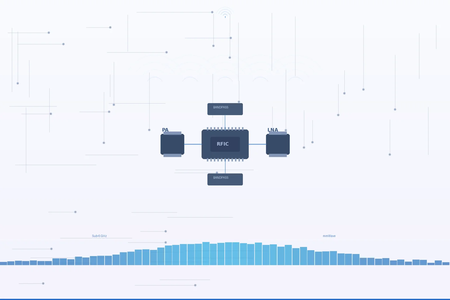
    The 5G CPE RF front-end sits between the modem baseband processor and the antenna system, performing the critical signal conditioning that enables the modem to demodulate weak received signals and transmit at sufficient power levels. In a typical sub-6 GHz 5G CPE design, the RFFE consists of four primary functional blocks arranged in transmit and receive chains:

    • Transmit chain: Baseband I/Q signals → Transceiver → Power Amplifier (PA) → Bandpass Filter → Antenna Switch → Antenna
    • Receive chain: Antenna → Antenna Switch → Bandpass Filter → Low-Noise Amplifier (LNA) → Transceiver → Baseband I/Q signals

    Review the RF front end as part of the finished CPE configuration, including supported bands, antenna paths and operating modes. Use model documentation and representative signal tests to assess link performance.

    Low-Noise Amplifier (LNA) Selection: Noise Figure and Linearity Tradeoffs

    The LNA is the first active component in the receive chain and the dominant contributor to the overall receiver noise figure as described by the Friis formula. In 5G CPE applications, LNA selection involves navigating a three-way tradeoff between noise figure (NF), linearity (measured as IIP3 — input third-order intercept point), and power consumption.

    For sub-6 GHz 5G CPE targeting n77/n78 bands (3.3-4.2 GHz), state-of-the-art LNAs fabricated in SOI (Silicon-on-Insulator) or SiGe (Silicon-Germanium) processes achieve noise figures between 0.8 dB and 1.5 dB with IIP3 values of +5 to +10 dBm. GaAs (Gallium Arsenide) pHEMT LNAs offer marginally better noise figures (0.5-1.0 dB) at higher cost and with more limited integration density. For mmWave CPE operating in n257/n258/n261 bands (24-40 GHz), the LNA design challenge intensifies significantly — noise figures below 2.5 dB at 28 GHz with IIP3 above 0 dBm represent a competitive benchmark that separates premium RFFE designs from commodity implementations.

    Procurement evaluation point: Request the RFFE bill of materials (BOM) or at minimum the LNA vendor and model family. Leading LNA suppliers for 5G CPE designs include Skyworks (SKY5 series), Qorvo (QPF series), and Qualcomm (ultraSAW RF front-end modules). The presence of an integrated LNA-plus-filter module (e.g., Qualcomm ultraSAW or Broadcom FBAR-BAW duplexer-LNA combo) indicates a more mature, size-optimized design versus discrete implementations.

    Power Amplifier (PA): Efficiency, Linearity, and Thermal Budget

    Review the power amplifier design with the device supplier against the required bands, output configuration and applicable test documentation. Component-level values alone do not establish finished-device throughput.

    Check the complete device power budget, including modem, RF, Ethernet, local WiFi and any proposed compute functions. Confirm compatibility with the supplied power equipment for the ordered configuration.

    Envelope tracking (ET) and average power tracking (APT) are two PA supply modulation techniques that improve efficiency by dynamically adjusting the PA supply voltage to match the instantaneous signal envelope. ET-capable PAs can improve PAE by 15-25 percentage points compared to fixed-supply designs, at the cost of additional ET modulator IC complexity. For CPE designs targeting always-on operation with tight thermal constraints — such as DIN-rail industrial CPE without active cooling — ET implementation should be considered a significant differentiator.

    Filter Technologies: Acoustic Wave Filters and Coexistence Challenges

    Bandpass filters in the 5G CPE RFFE perform two essential functions: suppressing out-of-band emissions in the transmit path (to meet 3GPP spectrum emission masks) and rejecting out-of-band blockers in the receive path (to prevent LNA saturation from adjacent-channel interferers). The filter technology selection — SAW (Surface Acoustic Wave), BAW (Bulk Acoustic Wave), or FBAR (Film Bulk Acoustic Resonator) — carries significant implications for insertion loss, selectivity, and temperature stability.

    For sub-6 GHz 5G CPE, BAW and FBAR filters have largely superseded SAW technology for bands above 2.5 GHz due to their superior Q-factor (2000-3000 vs. 500-1000 for SAW) and lower temperature coefficient of frequency (TCF: -15 to -25 ppm/°C vs. -30 to -45 ppm/°C for SAW). A CPE deployed outdoors in the Middle East, where enclosure temperatures can reach +70°C, may experience 3-5 dB of additional insertion loss with SAW filters due to TCF drift — effectively halving the link budget margin.

    Coexistence filtering is an underappreciated procurement consideration. 5G CPE operating in n78 (3.3-3.8 GHz) must coexist with Wi-Fi 6E/7 in the adjacent 5.925-7.125 GHz band and with C-band satellite downlinks in the 3.7-4.2 GHz range. A well-designed RFFE incorporates dedicated coexistence filters with steep skirt selectivity (typically >40 dB rejection within 50 MHz of the band edge) to prevent self-interference when the CPE’s own Wi-Fi transmitter desensitizes the 5G receiver. Integrated RFFE modules that combine PA, LNA, switch, and filters with pre-verified coexistence performance — such as Qualcomm’s RFFE portfolio for the X75/X80 modem platforms — eliminate a significant integration risk.

    Antenna Switch and Diversity Architecture

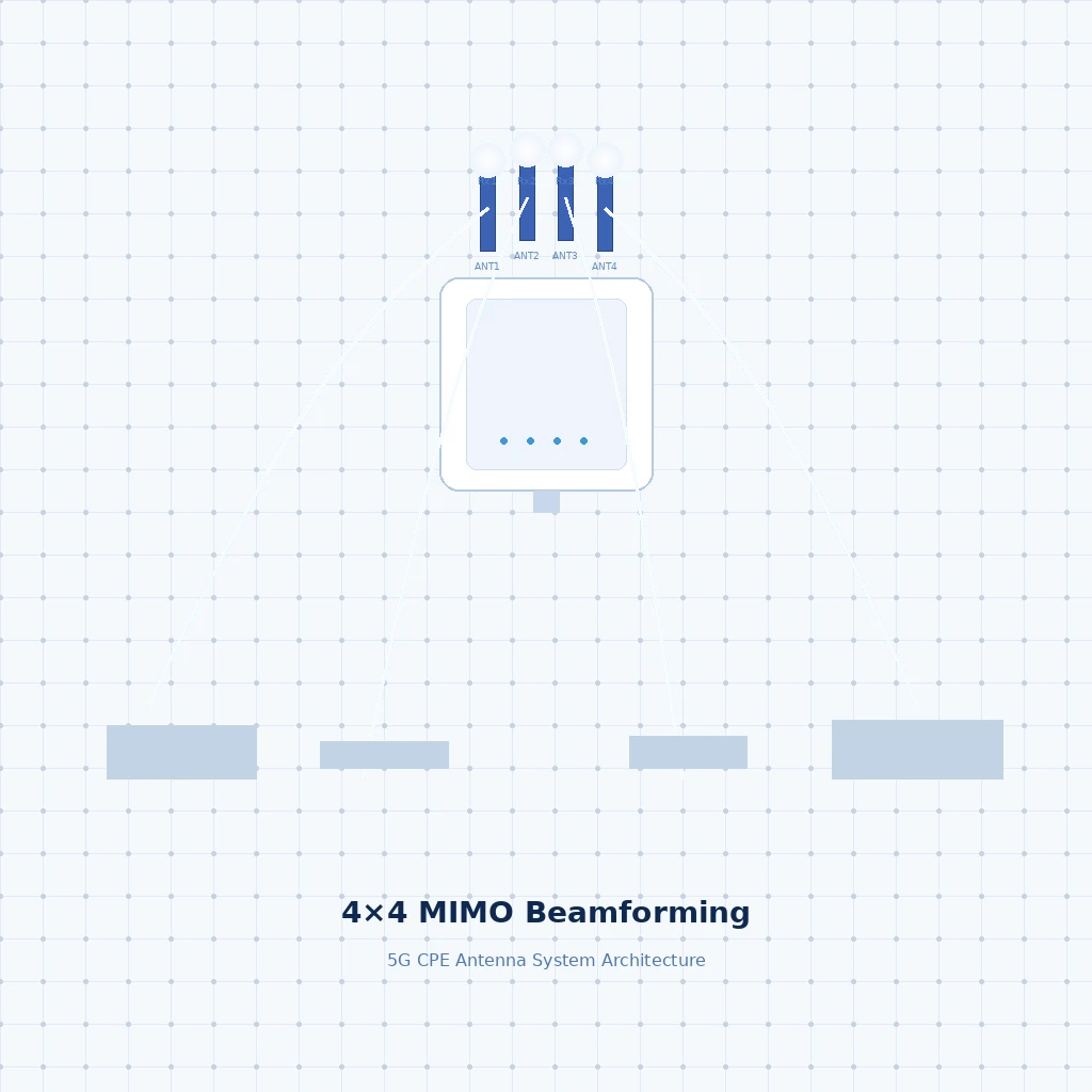
    The antenna switch module routes the transmit and receive signals between the RFFE chains and the physical antenna ports. In 5G CPE supporting 4×4 MIMO in sub-6 GHz, this switch matrix becomes complex: four independent receive chains must connect to four antenna ports with appropriate isolation, while the transmit chain(s) must access one or two of those antennas depending on whether 1T4R or 2T4R SRS (Sounding Reference Signal) antenna switching is supported.

    Switch insertion loss — typically 0.3-0.8 dB per throw in SOI technology — accumulates across the RFFE chain. A CPE design with 2.5 dB of cumulative switch loss between antenna and LNA input effectively converts an LNA with 1.0 dB NF into a system NF of 3.5 dB. Procurement evaluation should verify the total RFFE cascade noise figure from antenna connector to modem input, not just the LNA datasheet NF in isolation.

    mmWave RFFE: Beamforming and AiP Integration

    The mmWave RFFE for 5G CPE represents a departure from sub-6 GHz architecture due to the integration of the antenna array and beamforming IC into a single Antenna-in-Package (AiP) module. A typical mmWave CPE AiP integrates 4×2 or 8×2 dual-polarized patch antenna elements with per-element phase shifters and amplitude controllers, driven by beamforming transceiver ICs fabricated in advanced CMOS or SiGe processes.

    The procurement-relevant performance parameters for mmWave AiP modules include: Effective Isotropic Radiated Power (EIRP), typically 40-50 dBm for CPE-class devices (compared to 55-65 dBm for gNB base stations); beam scanning range of ±60° in both azimuth and elevation; and the number of simultaneously supported beams (typically 1-2 for CPE versus 4-8 for infrastructure). Qualcomm’s QTM series (QTM545 for X75, QTM565 for X80) and MediaTek’s Stellar series represent the primary merchant AiP platforms available to CPE OEM/ODM manufacturers.

    Integrated RFFE Modules vs. Discrete Implementation: Build-vs-Buy for CPE OEMs

    Compare an integrated RF module and a discrete implementation against the project requirements, documentation, design support and validation plan. Size and cost benefits require evidence for the particular designs being compared.

    Discrete RFFE implementations give CPE OEMs the freedom to select best-in-class components for each function — pairing a premium Skyworks PA with a Qorvo BAW filter and a custom-designed antenna switch, for example. This approach typically yields 1-2 dB better cascade NF and 2-3 percentage points better PAE than integrated modules, but requires significant RF engineering expertise for impedance matching, isolation, and coexistence debugging. For procurement teams evaluating CPE vendors, discreet RFFE designs with published cascade analysis indicate higher RF engineering maturity than “module-in-a-box” approaches, but carry proportionally higher integration risk and longer bring-up cycles.

    RFFE Procurement Checklist for 5G CPE Evaluation

    • LNA noise figure: <1.5 dB for sub-6 GHz (n77/n78), <2.5 dB for mmWave. Request cascade NF from antenna connector to modem input, not isolated LNA datasheet values.
    • Power-amplifier review: obtain RF performance and thermal data for the intended bands, modulation and operating conditions. Agree design targets from the complete radio requirements rather than applying one efficiency threshold to all designs.
    • Filter technology: BAW or FBAR for bands above 2.5 GHz. Verify temperature stability (TCF) for outdoor deployment environments. Confirm coexistence filtering for Wi-Fi 6E/7 and adjacent-band scenarios.
    • Switch loss: Total switch insertion loss from antenna port to LNA input should not exceed 1.5 dB in 4×4 MIMO sub-6 GHz designs.
    • MIMO support: 4×4 MIMO in sub-6 GHz with SRS antenna switching for 2T4R operation. Full-rank MIMO capability at the RFFE level, not just modem baseband.
    • mmWave AiP: EIRP >40 dBm, beam scanning ±60° azimuth/elevation, dual-polarization. Verify AiP vendor and generation (e.g., Qualcomm QTM545/QTM565).
    • Integration approach: Integrated RFFE modules for time-to-market priority; discrete implementations for performance optimization. Request cascade analysis documentation.
    • Component vendor transparency: Ability to disclose RFFE BOM (Skyworks, Qorvo, Qualcomm, Broadcom, Murata) indicates supply chain maturity and simplifies second-source planning.

    Outlook: RFFE Evolution Toward 5G-Advanced and 6G

    The 3GPP Release 18 and 19 roadmap introduces several RFFE-impacting features. Carrier aggregation combinations expanding to 4CC and 5CC in sub-6 GHz will demand multiplexers and quadplexers with tighter inter-band isolation. AI/ML-based RAN beam management — being standardized in Release 18 — will require RFFE with faster antenna switching speeds and the ability to perform channel sounding across antenna ports within the 5G slot duration. And the emergence of FR3 spectrum (7-24 GHz), being studied for 6G, will create an entirely new RFFE design space between sub-6 GHz and mmWave, requiring novel filter and amplifier topologies that bridge the gap between acoustic wave and AiP technologies.

    For procurement teams and system integrators building multi-year 5G CPE deployment roadmaps, the RFFE architecture is not a commoditized detail — it is the hardware foundation that determines whether a CPE can deliver its promised throughput, range, and reliability across diverse deployment environments. Investing the evaluation effort to compare RFFE designs at the component and cascade level produces durable procurement decisions that outlast any individual modem generation.

    For technical consultation on Honlly Telecom’s 5G CPE RFFE design methodology and customization options for carrier-grade deployments, contact our hardware engineering team.

  • 5G CPE Antenna Site Testing and Acceptance

    5G CPE Antenna Site Testing and Acceptance

    Use an antenna pilot to determine whether the proposed CPE and installation meet the project requirements. Start with the device specification, target operator and actual mounting locations. A test at a convenient desk or outside a building is not a substitute for testing the installation point.

    Identify the exact configuration

    Record the model revision, firmware, supported bands and antenna arrangement. Ask whether an external connection is available on the ordered variant and obtain the compatible antenna and cable requirements before selecting accessories.

    Plan a repeatable comparison

    Keep the SIM, service, device configuration and application workload consistent while comparing candidate locations or accessories. Record each change so the results can be interpreted. Include representative operating periods rather than relying on one speed-test result.

    Record link and application behaviour

    Save the signal readings exposed by the device, the installation position, traffic results and any reconnection events. Evaluate the application’s needs as well as a headline download result. The available signal readings and diagnostic functions must be confirmed for the firmware.

    Review mounting and servicing

    Include cable routing, weather exposure, physical access and power arrangements in the acceptance review. Check the enclosure and operating limits of the selected model. Do not assume that antenna gain or antenna count determines a fixed coverage improvement.

    Approve the documented installation

    Agree the target locations, acceptance criteria and any remaining conditions before ordering. Retain the tested device and accessory references so the production installation can be matched to the approved sample.

    Compare device specifications · Discuss a project configuration

  • 5G RedCap CPE Unlocks Scalable IoT Connectivity as NR-Light Ecosystem Matures for Industrial Sensor Networks in 2026

    5G RedCap CPE Unlocks Scalable IoT Connectivity as NR-Light Ecosystem Matures for Industrial Sensor Networks in 2026

    The industrial IoT landscape is undergoing a fundamental shift in 2026. While full-spec 5G eMBB CPE delivers multi-gigabit throughput for demanding enterprise applications, a vast middle ground of industrial sensor networks has remained underserved — until now. 5G RedCap (Reduced Capability), standardized as NR-Light in 3GPP Release 17 and further enhanced in Release 18, is emerging as the connectivity backbone for mid-tier IoT deployments, and a new generation of purpose-built RedCap CPE is hitting the market to serve this demand.

    What Is 5G RedCap and Why Does It Matter for CPE?

    5G RedCap — formally defined in 3GPP TS 38.101-1 — is a device class that sits between high-performance eMBB (enhanced Mobile Broadband) devices and ultra-low-power LPWA (Low Power Wide Area) technologies like NB-IoT and LTE-M. It was designed to address use cases that need more capability than LPWA can offer but don’t require the full bandwidth, carrier aggregation, or MIMO layers of premium 5G devices.

    For CPE manufacturers and enterprise buyers, the key RedCap device parameters are:

    • Maximum bandwidth: 20 MHz in FR1 (sub-7 GHz), compared to 100 MHz for full eMBB devices
    • Downlink MIMO layers: 1 or 2 Rx antennas (vs. 4 for premium 5G CPE), with mandatory 1 Tx
    • Peak data rate: Approximately 150 Mbps downlink, 50 Mbps uplink — more than sufficient for most industrial sensor aggregation
    • Half-duplex FDD support: Optional in Release 17, enabling further cost reduction by eliminating the duplexer
    • Reduced power consumption: Significantly lower than eMBB CPE through reduced bandwidth monitoring, fewer RF chains, and extended DRX cycles

    These constraints translate directly into tangible benefits for industrial IoT deployments: lower device BOM costs (estimated 60-70% reduction vs. full 5G CPE), smaller form factors suitable for DIN-rail or machine-mounted installation, and dramatically reduced power envelopes that make PoE-powered or even battery-backed operation practical.

    The RedCap CPE Value Proposition for Industrial Deployments

    In smart manufacturing environments, a single production line can host dozens of sensor types — vibration monitors, temperature probes, pressure transducers, current clamps, flow meters — each generating modest data volumes but collectively requiring reliable, low-latency backhaul to edge compute nodes or cloud analytics platforms. Traditional approaches have relied on industrial Wi-Fi mesh (with its interference and handover challenges) or wired Ethernet (with cabling complexity and inflexibility).

    RedCap CPE changes this equation in three ways:

    1. Cost-Effective Density. At a projected per-unit cost of $80-150 at scale, RedCap CPE makes it economically viable to deploy cellular backhaul for individual machine clusters or production cells, rather than sharing a single high-cost eMBB gateway across an entire facility. This granular deployment model improves network resilience — a single CPE failure affects a limited zone rather than the entire operation.

    2. Native 5G Core Integration. Unlike Wi-Fi-to-cellular bridges that introduce protocol translation overhead, RedCap CPE connects natively to the 5G Core (5GC). This means industrial deployments benefit from 5G-native features including network slicing (isolating sensor traffic from other enterprise data flows), URLLC-adjacent latency profiles (sub-10ms RTT in optimized private 5G networks), and unified device authentication through 5G-AKA.

    3. Simplified Spectrum Access. RedCap CPE operates in the same licensed, shared, or private 5G spectrum as eMBB devices, eliminating the coordination complexity of managing separate connectivity technologies. For enterprises deploying private 5G networks (in n77, n78, n79, or locally licensed spectrum), adding RedCap CPE to the device ecosystem requires no additional spectrum planning or regulatory approvals.

    3GPP Release 18 Enhancements: eRedCap and Beyond

    The 3GPP Release 18 specification (completed in mid-2024, with commercial silicon now reaching volume production in 2026) introduces eRedCap — a further reduced-capability tier that narrows the bandwidth to 5 MHz and targets peak data rates around 10 Mbps. While eRedCap overlaps somewhat with LTE Cat-1bis territory, its 5G-native architecture brings advantages in power efficiency (through advanced DRX and wake-up signal mechanisms) and simplified network integration for operators that are consolidating around a 5G-only core.

    For CPE procurement teams, the key takeaway is that the RedCap silicon ecosystem is now mature. Qualcomm’s Snapdragon X35 5G Modem-RF system, MediaTek’s T300, and UNISOC’s V517 have all reached volume availability, giving CPE vendors multiple silicon paths to RedCap product development. Module-level products from Quectel, Fibocom, and Sierra Wireless further reduce integration complexity for CPE OEMs.

    Deployment Scenarios Driving RedCap CPE Adoption

    Smart Factory Sensor Aggregation. In discrete manufacturing, a RedCap CPE mounted at each production cell aggregates data from 10-30 wired or short-range wireless sensors (via integrated Ethernet, RS-485, or Bluetooth LE backhaul) and relays aggregated telemetry to the MES (Manufacturing Execution System) or cloud-based digital twin platform over the 5G network. The per-cell redundancy model eliminates single points of failure that plague centralized gateway architectures.

    Utility and Energy Sector Monitoring. Electrical substations, water treatment facilities, and renewable energy sites increasingly require always-on connectivity for condition monitoring without the fiber backhaul costs that have historically limited deployment density. RedCap CPE with integrated GPS/GNSS provides both telemetry backhaul and precise timing reference for synchrophasor applications in grid monitoring.

    Logistics and Warehouse Asset Tracking. Large distribution centers are deploying RedCap CPE as fixed wireless infrastructure nodes that bridge Bluetooth- or UWB-based indoor positioning systems to the WMS (Warehouse Management System) cloud. The lower per-node cost compared to full 5G CPE enables coverage density that would be economically impractical otherwise.

    Agricultural and Environmental Monitoring. In precision agriculture, RedCap CPE deployed at weather stations, soil monitoring clusters, and irrigation control points provides reliable rural connectivity at price points that make per-field deployment viable. The extended coverage characteristics of 5G FR1 bands (particularly n28 700 MHz and n71 600 MHz) provide range advantages over unlicensed-spectrum alternatives.

    RedCap vs. LTE Cat-4/Cat-6: Why Make the Switch?

    Enterprise buyers evaluating RedCap CPE frequently ask whether existing LTE Cat-4 or Cat-6 devices are sufficient for their needs. While Cat-4/Cat-6 does offer comparable peak data rates (150 Mbps / 300 Mbps respectively), RedCap brings several architectural advantages that matter in industrial contexts:

    • 5G Core-native: RedCap devices authenticate and operate within the 5GC, enabling unified policy control, slicing, and QoS management across the entire device fleet — advantages lost when mixing LTE and NR access technologies
    • Lower latency floor: 5G NR’s flexible OFDM numerology enables shorter slot durations than LTE, translating to measurably lower baseline latency even at comparable throughput
    • Future-proof spectrum access: As operators progressively refarm LTE spectrum to NR (a trend accelerating through 2026-2028), Cat-4/Cat-6 devices face an uncertain connectivity future; RedCap ensures long-term spectrum compatibility
    • Power efficiency at scale: 5G’s advanced power-saving features — including RRC_INACTIVE state with RNA (RAN-based Notification Area), extended DRX with wake-up signaling, and reduced PDCCH monitoring — yield meaningful power savings in large-scale sensor deployments

    The CPE Manufacturer’s Opportunity

    For CPE vendors, RedCap represents a significant market expansion opportunity. While the eMBB CPE market is defined by performance differentiation (peak throughput, carrier aggregation capabilities, Wi-Fi 7 backhaul), the RedCap CPE market will be won on a different set of criteria: cost optimization, industrial interface breadth (Ethernet, RS-232/485, Modbus, CAN bus, discrete I/O), environmental hardening (extended temperature range, IP65+ ingress protection, vibration tolerance), and management scalability at fleet sizes an order of magnitude larger than typical enterprise CPE deployments.

    Honlly Telecom is actively developing RedCap CPE products that combine these industrial-grade design requirements with the ease of deployment and cloud-based fleet management that enterprise and system integrator customers demand. As the NR-Light ecosystem continues to mature through 2026 and beyond, RedCap CPE will become an indispensable building block of the industrial 5G connectivity fabric — not replacing eMBB CPE or LPWA technologies, but filling the critical middle ground where performance, cost, and scale converge.

  • A Technical Buyer’s Guide to Multi-Access Edge Computing (MEC) Integration in 5G CPE: Distributed Compute Architectures, Service Continuity, and Enterprise Edge Deployment Patterns

    A Technical Buyer’s Guide to Multi-Access Edge Computing (MEC) Integration in 5G CPE: Distributed Compute Architectures, Service Continuity, and Enterprise Edge Deployment Patterns

    As 5G networks mature beyond enhanced mobile broadband into enterprise and industrial use cases, Multi-Access Edge Computing (MEC) integration in Customer Premises Equipment (CPE) has emerged as one of the most architecturally significant trends in telecom procurement for 2026. By embedding distributed compute resources at the network edge — co-located with the CPE that terminates the 5G air interface — operators and enterprises can achieve application-layer latencies below 5 milliseconds, dramatically reduce backhaul bandwidth consumption, and enable a new class of latency-sensitive applications that centralized cloud architectures cannot economically support.

    This guide examines the key architectural considerations, platform selection criteria, and deployment patterns that procurement teams and network architects must evaluate when specifying MEC-capable 5G CPE for enterprise and industrial edge deployments.

    The MEC-CPE Convergence Architecture

    ETSI GS MEC 003 defines the Multi-Access Edge Computing framework that governs how compute, storage, and networking resources are distributed between the radio access network (RAN) and the enterprise premises. In a MEC-integrated 5G CPE, a compute module — typically based on ARM Cortex-A78AE or x86-64 embedded processors — is integrated alongside the 5G modem (Qualcomm X70/X80 or MediaTek T900 series), connected via PCIe Gen4 or high-speed chip-to-chip interconnect, and exposed to the operator or enterprise through a containerized application runtime environment.

    Three deployment topologies dominate the MEC-CPE landscape in 2026: CPE-resident MEC (compute module embedded within the CPE enclosure), co-located MEC (a compact edge server connected to the CPE via 10GbE or 25GbE), and distributed MEC mesh (multiple CPE devices pooling compute resources across a campus or industrial site via Kubernetes-orchestrated container scheduling). Each topology presents distinct trade-offs in cost, performance, and operational complexity.

    UPF Selection and Traffic Steering

    The 5G User Plane Function (UPF) is the critical control point that determines which traffic flows are routed to the MEC compute module versus forwarded to the centralized core network. In CPE-resident MEC architectures, a local UPF instance — often implemented as a lightweight software UPF running on the CPE’s embedded processor — performs traffic classification based on 5G QoS Flow Identifier (5QI), Network Slice Selection Assistance Information (NSSAI), or application-layer signatures (DNS, SNI, HTTP Host header).

    For procurement teams, the key UPF evaluation criteria include: whether the local UPF supports 3GPP Release 17/18 ULCL (Uplink Classifier) and branching point functionality for selective traffic offload; whether session continuity is maintained when a UE moves between CPEs (SSC Mode 2/3 with MEC service continuity); and whether the UPF exposes standard N4 interface to the Session Management Function (SMF) for policy-controlled traffic steering, or uses a proprietary API that locks the operator into a single CPE vendor ecosystem.

    Container Runtime and Application Orchestration

    MEC-capable 5G CPE platforms increasingly ship with pre-integrated Kubernetes (K3s or MicroK8s) or lightweight container runtime (containerd, CRI-O) environments, enabling operators and enterprises to deploy edge applications — video analytics engines, industrial protocol gateways (OPC UA, Modbus TCP, PROFINET), AI/ML inference models, or local breakout firewalls — directly on the CPE without additional hardware.

    The GSMA Operator Platform Group’s “Platform Enablement” framework, published in Q1 2026, standardizes the northbound APIs through which operators can manage containerized workloads across heterogeneous MEC-CPE fleets from multiple vendors. CPE platforms conforming to this framework expose a GSMA-defined MEC Application Enablement API, allowing a single operator edge orchestration platform to deploy, scale, and monitor applications across CPEs from different manufacturers — a critical requirement for operators avoiding vendor lock-in.

    Service Continuity and UE Mobility

    For enterprise deployments involving mobile users or assets — autonomous guided vehicles (AGVs) in warehouses, connected ambulances in smart city deployments, or mobile point-of-sale terminals at large event venues — MEC service continuity during UE handover between CPEs is the defining technical challenge. 3GPP Release 18 introduces enhancements to the Application Function (AF) influence on traffic routing that enable predictive MEC instance migration based on UE trajectory, but practical implementations depend heavily on CPE-side support for ETSI MEC RNIS (Radio Network Information Service) and bandwidth management APIs.

    Procurement teams evaluating MEC-CPE for mobility use cases should verify: SSC Mode 3 (make-before-break) support for seamless MEC session handover; RNIS API compliance for real-time radio condition awareness by edge applications; and whether the CPE supports inter-CPE direct communication via 5G sidelink (PC5) as a fallback when MEC service continuity via the core network is unavailable.

    Security Architecture for MEC-CPE

    Placing compute resources at the network edge expands the attack surface beyond what traditional CPE security architectures were designed to handle. MEC-CPE platforms must implement hardware-rooted trust chains that extend from the 5G modem’s secure boot through the compute module’s trusted execution environment (ARM TrustZone or Intel SGX) to the container runtime’s image signing and attestation pipeline.

    The GSMA NESAG (Network Equipment Security Assurance Group) v3.0 specification, adopted in early 2026, includes a dedicated MEC security profile (NESAG-MEC-01) that defines mandatory security requirements for MEC-integrated CPE, including: secure container image signing with Sigstore or Notary v2, runtime attestation via DICE (Device Identifier Composition Engine) or SPDM (Security Protocol and Data Model), mandatory mutual TLS (mTLS) between MEC applications and the operator’s edge orchestration platform, and network micro-segmentation between MEC application traffic and CPE management plane traffic using eBPF-based or IPsec-based isolation.

    Procurement Checklist for MEC-Capable 5G CPE

    When issuing RFPs for MEC-CPE platforms, procurement teams should include the following technical verification points:

    • Embedded compute: ARM Cortex-A78AE (or equivalent) with minimum 8 GB LPDDR5 RAM and 64 GB eMMC/UFS storage
    • Container runtime: Pre-integrated K3s/MicroK8s with OCI-compliant container image support
    • Local UPF: ULCL/branching point support per 3GPP TS 23.501, with N4 interface to SMF
    • Service continuity: SSC Mode 2 and Mode 3 support for UE mobility between MEC instances
    • GSMA Platform Enablement API compliance for multi-vendor workload orchestration
    • Security: NESAG-MEC-01 compliance, hardware root of trust, secure container attestation
    • Interconnect: PCIe Gen4 or chip-to-chip interconnect between 5G modem and compute module, minimum 10GbE SFP+ for co-located MEC
    • Power envelope: Maximum 45W total system power for CPE-resident MEC (including 5G modem and compute module)
    • Management: TR-369 USP with MEC workload lifecycle management data model extensions
    • Environmental: Industrial temperature range (-40°C to +65°C) for outdoor and factory-floor deployments

    As the MEC-CPE ecosystem matures through 2026 and into 2027, expect further convergence with AI acceleration hardware — integrated NPUs (Neural Processing Units) and FPGAs — enabling on-CPE inference for computer vision, predictive maintenance, and real-time natural language processing at the extreme edge. For operators and enterprises building their 5G edge strategy today, MEC-capable CPE represents the foundational hardware investment that will determine which applications, SLAs, and business models become technically and economically viable at the distributed edge.

  • Off-Grid 5G CPE Deployments Accelerate as Solar-Powered and Renewable Energy Base Stations Expand Rural and Remote Connectivity in 2026

    Off-Grid 5G CPE Deployments Accelerate as Solar-Powered and Renewable Energy Base Stations Expand Rural and Remote Connectivity in 2026

    The deployment of off-grid and solar-powered 5G Customer Premises Equipment (CPE) is accelerating across emerging markets and remote regions in 2026, as operators, tower companies, and government universal service programs seek cost-effective alternatives to grid-dependent infrastructure for the next wave of rural connectivity. With an estimated 850 million people globally still lacking access to reliable electricity in areas targeted for 5G fixed wireless access (FWA) expansion, renewable-energy-powered CPE is transitioning from a niche sustainability initiative to a mainstream procurement category.

    Solar-Powered CPE Architecture: Beyond the Panel

    Modern solar-powered 5G CPE integrates photovoltaic (PV) input, maximum power point tracking (MPPT) charge controllers, lithium iron phosphate (LiFePO₄) battery storage, and intelligent power management into a single outdoor-rated enclosure. Unlike early-generation solar router solutions that simply paired a consumer-grade CPE with an external solar kit, 2026-vintage integrated designs feature DC-native power architectures that eliminate inverter losses — converting solar energy directly to the 12V, 24V, or PoE (48V) power rails required by the CPE’s modem, processor, and RF front-end.

    The efficiency gains are substantial. A DC-native solar CPE architecture achieves end-to-end power conversion efficiency of 92–96%, compared to 75–82% for traditional AC-inverter-based solar setups. For a typical outdoor 5G FWA CPE drawing 18–25W during active transmission, this translates to a 20–30% reduction in required solar panel area and battery capacity — directly lowering total cost of ownership (TCO) for operators deploying thousands of rural sites.

    Battery Autonomy and the 72-Hour Benchmark

    Battery autonomy — the duration a CPE can operate on stored energy without solar input — has emerged as the critical specification differentiating carrier-grade off-grid CPE from entry-level solutions. Operators in regions with pronounced monsoon seasons (South and Southeast Asia), extended winter cloud cover (Northern Europe, Central Asia), or frequent sandstorm conditions (Middle East, North Africa) increasingly specify minimum 72-hour battery autonomy in their rural CPE RFPs.

    CPE vendors are responding with modular battery architectures that allow operators to scale storage capacity by adding LiFePO₄ battery packs in 100Wh, 200Wh, or 500Wh increments without replacing the core CPE unit. Intelligent discharge management — including dynamic power scaling that reduces CPE transmission power during extended low-solar periods to conserve battery while maintaining basic connectivity — extends effective autonomy beyond raw battery capacity calculations.

    Operator Deployment Momentum

    Several large-scale off-grid 5G CPE deployments have entered commercial operation in 2026, providing the ecosystem with much-needed field performance data. A Tier 1 Southeast Asian operator deployed 4,200 solar-powered 5G FWA CPE units across rural Indonesia in Q1 2026, achieving 97.8% network uptime through the peak of the monsoon season. In Sub-Saharan Africa, a multi-operator rural connectivity initiative backed by development finance institutions has committed to deploying 15,000 solar-powered 5G CPE units across Kenya, Tanzania, and Nigeria by Q4 2026.

    In Latin America, Brazil’s Anatel has incorporated off-grid CPE specifications into its universal service obligations for the 3.5 GHz 5G spectrum auction winners, mandating that at least 15% of rural FWA CPE deployments be solar-powered with minimum 48-hour battery autonomy. Similar regulatory frameworks are under development in India (TRAI consultation paper on green telecom, May 2026) and Nigeria (NCC draft guidelines on renewable energy for telecom infrastructure).

    Total Cost of Ownership Economics

    The business case for solar-powered 5G CPE has strengthened considerably as component costs have declined. LiFePO₄ battery pack costs have fallen below $75/kWh in volume procurement (down from $110/kWh in 2024), while high-efficiency monocrystalline PV panel prices have dropped to $0.18/W for utility-scale orders. Combined with the elimination of grid connection fees, trenching costs, and ongoing electricity expenses, operators report that solar-powered CPE achieves TCO parity with grid-powered alternatives at sites located more than 300 meters from existing grid infrastructure — and delivers 35–45% TCO savings at sites more than 1 kilometer from the grid.

    For operators, rural infrastructure funds, and government connectivity programs evaluating off-grid 5G CPE procurement in H2 2026, the key technical verification points include: DC-native power architecture (not AC-inverted), MPPT charge controller efficiency ≥97%, modular LiFePO₄ battery architecture with hot-swap capability, minimum 72-hour battery autonomy at rated load, IP67 or higher outdoor enclosure rating with passive cooling (no fans), and remote power monitoring via TR-369 USP or MQTT for fleet-level energy management. As the off-grid CPE ecosystem matures, expect further integration of AI-driven predictive energy management — optimizing battery charge/discharge cycles based on weather forecasts, traffic patterns, and time-of-day electricity pricing where hybrid grid-solar deployments are used.