Author: openclaw-Lisa-New

  • Open RAN and 5G CPE: What Vendor-Neutral Architecture Means for Telecom Procurement Strategy

    Open RAN and 5G CPE: What Vendor-Neutral Architecture Means for Telecom Procurement Strategy

    The Open RAN movement has fundamentally reshaped how mobile network operators think about infrastructure procurement. By disaggregating hardware and software and introducing standardized open interfaces between RAN components, Open RAN promises to break vendor lock-in, reduce total cost of ownership, and accelerate innovation cycles. But while much of the industry conversation focuses on radios, baseband units, and RIC platforms, a critical question for procurement teams is increasingly relevant: what does Open RAN mean for the CPE layer?

    The answer matters for ISPs, operators, MVNOs, and distributors who source customer-premises equipment. As networks transition toward open, interoperable architectures, the CPE devices connecting end users to those networks must evolve as well — and the implications for procurement strategy are significant.

    The Open RAN-CPE Interface: More Than Just Compatibility

    At a technical level, any standards-compliant 5G CPE should interoperate with any standards-compliant 5G RAN, regardless of whether that RAN is built on traditional integrated architecture or Open RAN principles. The 3GPP air interface specifications ensure this baseline compatibility. However, the procurement implications run deeper than simple radio interoperability.

    In an Open RAN environment, operators gain the freedom to mix and match RAN components from different vendors. This same philosophy naturally extends to the CPE layer: why should an operator who has embraced vendor diversity in their RAN infrastructure remain locked to a single CPE supplier? The logical endpoint of Open RAN thinking is a multi-vendor CPE strategy that mirrors the flexibility achieved at the infrastructure level.

    Procurement Advantages of Open RAN-Aligned CPE Strategy

    Supply Chain Resilience Through Vendor Diversification

    The global semiconductor shortage of 2021-2023 demonstrated that single-source CPE procurement is a business continuity risk. Operators who qualify multiple CPE vendors — and ensure their device management platforms can handle heterogeneous device fleets — build resilience against component shortages, trade disruptions, and vendor-specific quality issues. An Open RAN mindset applied to CPE procurement naturally leads to a qualified multi-vendor approach.

    Cost Optimization Through Competitive Tension

    When CPE procurement is locked to a single vendor — often the same vendor providing the RAN infrastructure — price negotiation leverage is limited. Open RAN’s separation of hardware and software creates a template for CPE procurement: decouple the device from the network infrastructure vendor relationship. This enables genuine competitive bidding for CPE contracts, driving down per-unit costs and improving commercial terms across the device lifecycle.

    Innovation Acceleration

    Independent CPE manufacturers, freed from the constraints of a single RAN vendor’s roadmap, can innovate faster on device-level features: advanced antenna designs, integrated edge computing capabilities, novel form factors, and AI-driven network optimization at the device level. Open RAN’s open interfaces encourage a similar dynamic at the CPE layer, where specialized device vendors can bring differentiated capabilities to operator deployments.

    Technical Considerations for Open RAN CPE Integration

    While baseline interoperability is guaranteed by 3GPP standards, operators pursuing Open RAN-aligned CPE strategies should evaluate several technical factors:

    O-RAN Alliance compliance testing: While O-RAN specifications primarily address the RAN infrastructure layer (O-DU, O-RU, O-CU), operators should verify that CPE devices have been tested against the specific O-RAN fronthaul and midhaul configurations deployed in their network. Subtle timing and synchronization behaviors can affect CPE performance at cell edges and during handover scenarios.

    RIC integration potential: The RAN Intelligent Controller (RIC) is a cornerstone of Open RAN architecture, enabling programmable optimization of radio resources. Forward-looking CPE devices that can expose performance telemetry via standardized APIs give operators the ability to feed device-side metrics into RIC optimization algorithms, creating a closed-loop optimization cycle that spans from the RAN through to the end-user device.

    Management plane unification: Operators should ensure that multi-vendor CPE fleets can be managed through a single pane of glass, whether using TR-369 USP, TR-069, or a carrier-developed management platform. The operational overhead of managing different CPE vendors through different management systems can quickly erode the cost benefits of multi-vendor procurement.

    What This Means for CPE Buyers

    For procurement decision-makers at ISPs, operators, and MVNOs, the Open RAN trend creates both opportunity and responsibility. The opportunity is clear: greater vendor choice, better pricing, and faster access to device innovation. The responsibility is equally important: building the internal capabilities to evaluate, qualify, and manage a multi-vendor CPE ecosystem.

    This means investing in interoperability testing labs, building vendor-agnostic device certification programs, and ensuring that procurement RFPs are written to encourage participation from independent CPE manufacturers rather than defaulting to the incumbent RAN vendor’s device portfolio.

    For Honlly Telecom, Open RAN alignment is a core design principle. Our CPE platforms are validated against leading O-RAN compliant infrastructure from multiple RAN vendors, ensuring that operators pursuing open architecture strategies can deploy Honlly devices with confidence. Our engineering team actively participates in interoperability testing programs and maintains readiness for the evolving O-RAN specification roadmap.

    To discuss Open RAN-compatible CPE solutions for your network deployment, contact Honlly Telecom at gerard@xmhonlly.com.
  • 5G RedCap CPE: Unlocking the Mid-Tier Connectivity Market for Operators and MVNOs

    5G RedCap CPE: Unlocking the Mid-Tier Connectivity Market for Operators and MVNOs

    As 5G networks mature globally, a critical market segment is emerging between high-performance eMBB devices and ultra-low-power NB-IoT modules. 5G RedCap (Reduced Capability), standardized in 3GPP Release 17 as NR-Light, is designed precisely for this middle ground — and it represents one of the most significant new revenue opportunities for operators, MVNOs, and equipment vendors in the current decade.

    For telecom buyers evaluating CPE procurement strategies, understanding RedCap is no longer optional. The technology promises to bring 5G-native connectivity to use cases that have historically relied on LTE Cat-4 or Cat-6 devices, but with the added benefits of 5G core integration, improved spectral efficiency, and native support for network slicing and URLLC-lite capabilities.

    What Makes RedCap Different

    RedCap occupies a deliberate middle tier in the 5G device landscape. Compared to full-specification 5G NR devices, RedCap CPE reduces complexity in several key areas: fewer receive antennas (typically 1-2 RX instead of 4), narrower maximum bandwidth (20 MHz in FR1 versus 100 MHz for eMBB), and half-duplex FDD operation as an option rather than a requirement. These simplifications translate directly into lower bill-of-materials cost, reduced power consumption, and smaller form factors — without sacrificing the 5G core network advantages that operators have invested billions to deploy.

    The target throughput range for RedCap — approximately 150 Mbps downlink and 50 Mbps uplink — sits comfortably above most LTE Cat-6 devices while coming in well below what premium 5G CPE delivers. For many enterprise and industrial use cases, this is exactly the right performance envelope.

    Operator Use Cases: Where RedCap CPE Fits

    Fixed Wireless Access for Light-Use Households

    Not every FWA subscriber needs gigabit throughput. In emerging markets and rural deployments, a RedCap-based CPE delivering 50-150 Mbps at a significantly lower device subsidy cost can make the difference between a viable business case and an unprofitable one. Operators can segment their FWA offerings, deploying premium full-spec 5G CPE to high-ARPU subscribers while using RedCap devices to economically serve price-sensitive segments.

    Industrial IoT and Smart Manufacturing

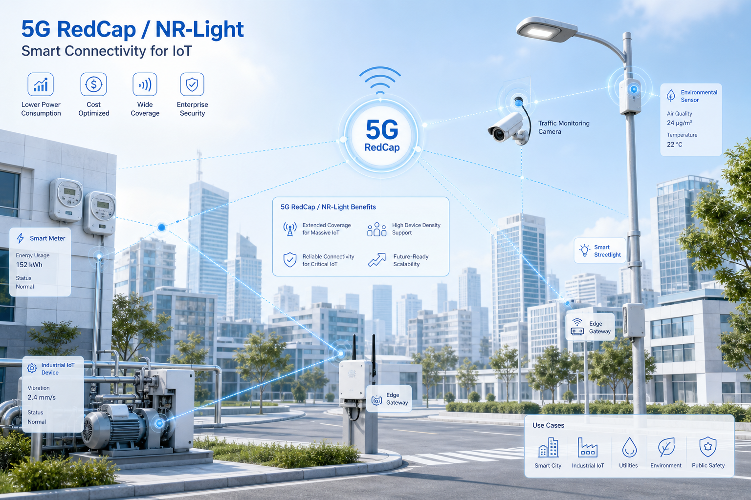
    Factory floors, logistics hubs, and processing plants require reliable connectivity for hundreds or thousands of endpoints: sensors, scanners, AGVs, and monitoring cameras. RedCap CPE can serve as on-premises gateways that aggregate these connections over a 5G backhaul, with the added benefit of 5G’s native QoS framework ensuring that critical control traffic receives guaranteed latency and reliability parameters.

    Smart City and Utility Deployments

    Municipal networks connecting smart meters, traffic management systems, public safety cameras, and environmental sensors have historically relied on fragmented connectivity solutions. A RedCap CPE deployment provides a unified 5G-native connectivity layer that can be centrally managed, sliced by application, and scaled across thousands of endpoints per city.

    Retail and Branch Office Connectivity

    For chain retailers, bank branches, and distributed enterprise locations, RedCap CPE offers an attractive alternative to traditional wired broadband backup. The device economics work at scale, the 5G core integration simplifies network management across hundreds of locations, and the performance envelope comfortably supports POS systems, video surveillance, and staff Wi-Fi.

    Procurement Considerations for Operators

    When evaluating RedCap CPE for your network, several factors merit careful attention:

    Chipset maturity: Qualcomm’s Snapdragon X35 and MediaTek’s T300 platforms are the leading RedCap modem solutions currently available. Both have been validated across major infrastructure vendors, but operators should verify interoperability with their specific RAN configuration and core network release version before committing to volume orders.

    Band support flexibility: RedCap operates in FR1 (sub-7 GHz) spectrum only. Ensure your selected CPE supports the specific band combinations used in your deployment markets, including any planned spectrum refarming initiatives that may shift band allocations during the device lifecycle.

    Management and provisioning: RedCap devices should integrate into the same TR-369 USP or TR-069 management platform used for your full-spec 5G CPE fleet. Device fragmentation across management systems erodes the operational efficiency gains that RedCap’s lower device cost is supposed to deliver.

    Future-proofing via eRedCap: 3GPP Release 18 introduces eRedCap (evolved RedCap), which further reduces complexity and targets even lower cost points for use cases like wearables and low-power sensors. When selecting a CPE partner, evaluate their roadmap for eRedCap support to ensure investment protection.

    The Market Timing Is Right

    Network infrastructure support for RedCap is expanding rapidly. Major RAN vendors including Ericsson, Nokia, and Huawei have shipped RedCap-capable software releases, and commercial RedCap device availability is scaling through 2026. Operators who move early to integrate RedCap into their CPE procurement strategy position themselves to capture market share in the mid-tier connectivity segment before it becomes commoditized.

    For Honlly Telecom, RedCap CPE represents a natural extension of our carrier-grade device portfolio. Our engineering team is actively developing RedCap-based platforms that maintain the same carrier-tested RF performance, thermal reliability, and remote management capabilities that operators expect from Honlly devices, while achieving the cost structure that mid-tier deployments demand.

    To discuss RedCap CPE requirements for your network, contact Honlly Telecom at gerard@xmhonlly.com.

  • Honlly Telecom Strengthens 5G CPE Portfolio with Next-Generation Solutions for Global Carrier Deployments

    Honlly Telecom Strengthens 5G CPE Portfolio with Next-Generation Solutions for Global Carrier Deployments

    Xiamen, China — Honlly Telecom, a specialized OEM/ODM manufacturer of 4G/5G wireless routers, MiFi devices, and CPE solutions, today announced a significant expansion of its 5G CPE product portfolio, introducing new hardware platforms designed to serve a broader range of carrier-grade fixed wireless access (FWA) deployment scenarios.

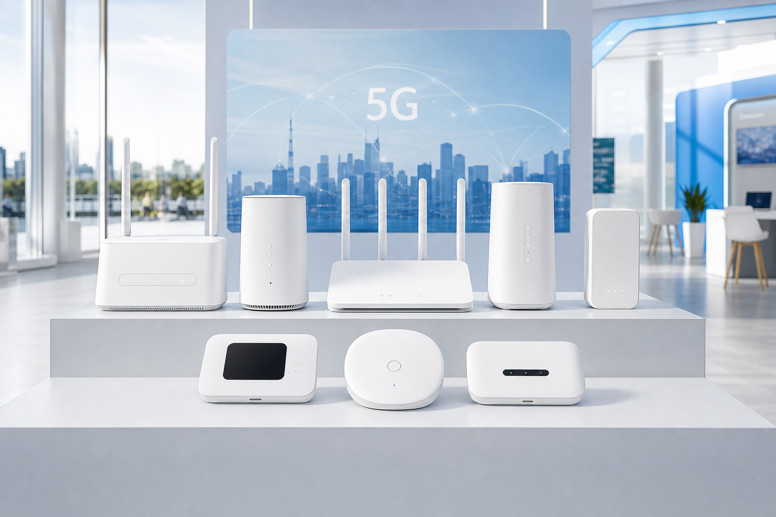
    The expanded portfolio now spans entry-level 5G CPE for cost-sensitive broadband replacement programs, mid-range models optimized for SME and multi-tenant environments, and high-performance outdoor units engineered for challenging RF conditions and long-range backhaul applications. Each platform is built on a modular hardware architecture that allows operators to customize band support, interface configuration, and industrial design to match specific regional deployment requirements.

    Portfolio Designed for Diverse Carrier Requirements

    The updated product line addresses a key market reality: no single CPE design fits every operator deployment. Tier-1 MNOs in dense urban markets have fundamentally different requirements than regional WISPs serving rural communities, and enterprise private network deployments demand yet another set of specifications around security, management, and environmental hardening.

    Honlly’s approach combines a shared software platform with flexible hardware configurations, giving procurement teams at ISPs, operators, and MVNOs the ability to specify exactly the right device for each deployment tier without fragmentation in their management and OTA update infrastructure. Common elements across all platforms include Honlly’s carrier-tested RF front-end design, advanced thermal management, and full TR-369 USP support for zero-touch provisioning at scale.

    Addressing the Full FWA Value Chain

    The portfolio expansion reflects feedback from Honlly’s operator partners across Southeast Asia, Africa, the Middle East, and Latin America, where FWA adoption is accelerating as a primary broadband access technology. According to industry data, FWA connections are projected to exceed 300 million globally by 2027, with the majority of growth coming from emerging markets where fixed-line infrastructure is limited.

    “Operators are moving past the trial phase and into mass deployment. That changes procurement priorities — cost optimization, supply chain reliability, and lifecycle management become just as important as raw throughput performance,” said a spokesperson for Honlly Telecom. “Our expanded portfolio is a direct response to what our carrier customers have been asking for: a single trusted manufacturing partner that can deliver devices across the entire deployment spectrum, from indoor desktop units to ruggedized outdoor CPE.”

    Manufacturing Scale and Customization Capabilities

    All products in the expanded portfolio are manufactured at Honlly’s ISO 9001-certified production facility in Xiamen, which supports flexible production runs from pilot batches to high-volume carrier orders exceeding 100,000 units per month. The company’s in-house engineering team provides full customization services including industrial design, UI/UX localization, packaging design, and firmware feature development tailored to operator specifications.

    For operators and distributors evaluating 5G CPE procurement partners, Honlly offers comprehensive sampling programs, interoperability testing support with major network infrastructure vendors, and dedicated regional technical support throughout the deployment lifecycle.

    Looking Ahead

    Honlly Telecom continues to invest in next-generation CPE technologies, with active development programs in Wi-Fi 7 integration, 5G RedCap for IoT and mid-tier use cases, and AI-driven network optimization embedded at the device level. The company will showcase its expanded portfolio at upcoming industry events across Asia and the Middle East in the second half of 2026.

    For product specifications, sampling requests, or partnership inquiries, contact Honlly Telecom at gerard@xmhonlly.com or visit honllytelecom.com/contact.

  • A Technical Buyer’s Guide to 5G CPE ODM/OEM Partner Selection: Manufacturing Quality Assurance, R&D Capability Assessment, and Supply Chain Resilience for Carrier-Grade FWA Deployments

    A Technical Buyer’s Guide to 5G CPE ODM/OEM Partner Selection: Manufacturing Quality Assurance, R&D Capability Assessment, and Supply Chain Resilience for Carrier-Grade FWA Deployments

    The Strategic Importance of ODM/OEM Partner Selection in 5G FWA

    For mobile network operators, ISPs, and enterprise solution providers building 5G Fixed Wireless Access (FWA) product portfolios, the selection of an ODM (Original Design Manufacturer) or OEM (Original Equipment Manufacturer) partner is not merely a procurement decision — it is a strategic commitment that shapes product quality, time-to-market velocity, total cost of ownership, and long-term competitive positioning. The global 5G CPE supply chain has matured significantly in 2026, with a growing number of manufacturers offering ostensibly similar hardware specifications. Yet the variance in engineering depth, manufacturing quality, certification readiness, and post-deployment support capability remains substantial. This guide provides a structured framework for evaluating ODM/OEM partners in the 5G CPE segment.

    Manufacturing Quality Assurance: Beyond ISO 9001

    While ISO 9001 certification represents a baseline requirement, carrier-grade CPE manufacturing demands significantly more rigorous quality management systems. Prospective buyers should evaluate partners against a multi-dimensional quality framework that encompasses:

    Production Line Automation and Traceability: Best-in-class 5G CPE manufacturers operate fully automated SMT (Surface-Mount Technology) lines with Automated Optical Inspection (AOI) at every stage, in-circuit testing (ICT), and functional testing with full RF parametric verification. Every unit should carry a unique serial number traceable through the entire manufacturing lifecycle — from component reel to final shipment — enabling rapid root-cause analysis in the event of field failures.

    Environmental Stress Screening (ESS): Carrier-grade CPE undergoes accelerated life testing including thermal cycling (−40°C to +85°C), humidity exposure (95% RH at 65°C), vibration testing per IEC 60068-2-6, and salt fog testing for coastal deployment scenarios. Partners should provide ESS batch reports as standard documentation with every production run, not as optional extras.

    First-Pass Yield and DPPM Metrics: Request historical first-pass yield (FPY) data for comparable 5G CPE products — top-tier manufacturers consistently achieve FPY above 96% on complex multi-band CPE assemblies. Defective Parts Per Million (DPPM) targets should be below 500 for carrier-grade shipments, with contractual remedies for batches exceeding this threshold.

    Component Sourcing and Counterfeit Prevention: The global semiconductor supply chain, while stabilizing in 2026, remains susceptible to counterfeit components. Verify that the partner maintains authorized distributor relationships with all major chipset vendors (Qualcomm, MediaTek, Broadcom, Infineon) and operates a documented counterfeit component prevention program aligned with SAE AS5553 or equivalent standards.

    R&D Capability Assessment: Engineering Depth That Differentiates

    Hardware specifications on a datasheet tell only part of the story. The true value of an ODM/OEM partnership lies in the engineering capability to customize, optimize, and evolve products throughout their lifecycle. Key evaluation dimensions include:

    RF Engineering Competency: 5G CPE RF design is fundamentally more complex than 4G LTE. Multi-band support spanning Sub-6GHz and mmWave frequencies requires sophisticated antenna design, impedance matching across wide bandwidths, and MIMO array optimization. Evaluate the partner’s in-house antenna design capability — including anechoic chamber facilities for radiation pattern measurement, SAR compliance testing, and OTA (Over-The-Air) TRP/TIS characterization. Partners relying entirely on third-party antenna reference designs will struggle with carrier-specific optimization requirements.

    Firmware and Software Engineering: The software stack in a 5G CPE device — encompassing the modem firmware, Wi-Fi driver, network protocol stack, TR-069/TR-369 management agent, and Web UI/API — represents 60–70% of total development effort. Strong ODM partners maintain dedicated software teams for each layer, with demonstrated capability in OpenWrt/Yocto-based platform development, carrier-specific customization (VoNR/VoLTE IMS integration, IPv4/v6 dual-stack, CG-NAT handling), and OTA firmware update infrastructure.

    Certification Engineering: Global certification complexity is one of the most underestimated costs in 5G CPE deployment. A competent ODM partner should have in-house certification engineering teams familiar with: GCF/PTCRB for 3GPP compliance, FCC Part 15/Part 96 for US market access, CE RED for European Union, Anatel for Brazil, NCC for Taiwan, and additional country-specific requirements. Pre-certification testing capability — including conducted RF testing, radiated spurious emissions measurement, and protocol conformance testing — significantly reduces certification cycle time and cost.

    IP Portfolio and Innovation Track Record: Evaluate the partner’s patent portfolio in 5G CPE-related technologies — antenna design, thermal management, power efficiency, and network optimization algorithms. Partners investing in original R&D are more likely to deliver differentiated products and sustain technical competitiveness over multiple product generations.

    Supply Chain Resilience: Lessons from 2020–2025

    The semiconductor shortages of 2020–2023 and subsequent supply chain disruptions through 2024–2025 reshaped expectations for ODM/OEM supply chain management. In 2026, operators should evaluate partners against concrete resilience metrics:

    Multi-Source Component Strategy: For critical components — including PMICs, RF front-end modules, memory (DDR/LPDDR, eMMC/UFS), and passive components — the partner should maintain qualified alternate sources with validated pin-to-pin compatibility. Single-sourced components should be identified transparently, with documented risk mitigation plans including buffer stock commitments.

    Geographic Manufacturing Diversification: Partners with manufacturing facilities in multiple countries provide natural hedging against geopolitical disruption, trade policy changes, and regional logistics bottlenecks. Evaluate whether the partner can shift production volumes between facilities within 8–12 weeks if required.

    Inventory Management Philosophy: While just-in-time (JIT) manufacturing minimizes working capital, carrier-grade supply assurance requires strategic buffer inventory for long-lead-time components. The optimal partner maintains 8–12 weeks of buffer stock for sole-sourced semiconductors and 4–6 weeks for multi-sourced components, with transparent inventory reporting provided quarterly.

    Commercial and Partnership Model Evaluation

    Beyond technical capability, the commercial partnership structure significantly impacts long-term success:

    MOQ Flexibility: Evaluate minimum order quantities (MOQs) for both initial pilot runs and volume production. Partners offering pilot runs of 100–500 units with per-unit pricing transparency enable operators to validate product-market fit before committing to volume orders. Beware of partners whose pricing models obscure significant non-recurring engineering (NRE) charges behind apparently attractive unit pricing.

    Customization Cost Structure: Obtain detailed NRE quotations for common customization requests: industrial design modifications (enclosure, branding, LED/UI changes), firmware customization (Web UI theming, TR-069 data model extensions, operator-specific feature development), and certification support for new target markets. Partners with modular platform architectures typically deliver customization 30–50% faster and at lower NRE than those working from single-project reference designs.

    Post-Deployment Support: Field failures are inevitable in any large-scale CPE deployment. The partner’s RMA process, failure analysis turnaround time (target: < 15 business days), firmware bug fix SLA (target: critical bugs resolved within 72 hours), and field support escalation path should be contractually defined before the first purchase order.

    The Honlly Telecom ODM/OEM Advantage

    At Honlly Telecom, our ODM/OEM partnership model is built on 18 years of wireless CPE manufacturing excellence. We operate ISO 9001:2015-certified production facilities with fully automated SMT lines, in-house anechoic chambers for antenna design and OTA testing, and dedicated R&D teams covering 4G LTE and 5G NR CPE platforms across Sub-6GHz and mmWave frequencies. Our supply chain resilience framework maintains strategic buffer inventory across all critical semiconductor components, and our multi-facility manufacturing capability provides geographic diversification for supply assurance.

    We differentiate through engineering depth — our teams collaborate directly with operator engineering groups on antenna optimization, firmware customization, certification testing, and field trial support. We view each partnership not as a transactional supplier relationship but as a collaborative engineering engagement focused on delivering carrier-grade products that perform reliably in real-world deployment conditions.


    Contact Honlly Telecom to discuss your 5G CPE ODM/OEM requirements. Email gerard@xmhonlly.com or visit honllytelecom.com to schedule a confidential engineering consultation and receive sample units for evaluation.

  • A Technical Buyer’s Guide to Wi-Fi 7 Integration in 5G CPE: Multi-Link Operation, 320 MHz Channel Bonding, and 4K QAM for Next-Generation Fixed Wireless Access Gateways

    A Technical Buyer’s Guide to Wi-Fi 7 Integration in 5G CPE: Multi-Link Operation, 320 MHz Channel Bonding, and 4K QAM for Next-Generation Fixed Wireless Access Gateways

    Why Wi-Fi 7 Matters for 5G Fixed Wireless Access

    The intersection of 5G Fixed Wireless Access (FWA) and Wi-Fi 7 (IEEE 802.11be) represents one of the most significant architectural advancements in residential and enterprise broadband delivery. As 5G FWA services routinely deliver 500 Mbps to 2 Gbps at the WAN interface, the local-area wireless distribution must keep pace — and Wi-Fi 6/6E, while capable, cannot fully exploit the multi-gigabit potential that mmWave and carrier-aggregated Sub-6GHz FWA connections enable. For operators, ISPs, and enterprise buyers evaluating 5G CPE gateways in 2026, understanding Wi-Fi 7 integration is now a critical procurement competency.

    Multi-Link Operation (MLO): The Wi-Fi 7 Game-Changer

    Multi-Link Operation (MLO) is the defining innovation of Wi-Fi 7 and the feature most directly relevant to 5G CPE performance. MLO enables a single Wi-Fi 7 access point — embedded within the 5G CPE gateway — to simultaneously transmit and receive data across multiple frequency bands (2.4 GHz, 5 GHz, and 6 GHz) using multiple radio links aggregated into a single logical connection.

    For FWA deployments, MLO delivers three transformative benefits. First, throughput aggregation: by bonding a 5 GHz channel and a 6 GHz channel simultaneously, MLO can push aggregate throughput beyond 5 Gbps at the local network level, ensuring the Wi-Fi distribution never becomes the bottleneck for multi-gigabit 5G WAN connections. Second, latency reduction: MLO’s simultaneous transmit/receive capability across bands allows the CPE to select the least-congested link for latency-sensitive traffic in real time, reducing worst-case latency by 40–60% compared to single-link Wi-Fi 6 operation. Third, reliability enhancement: if one band experiences interference or congestion, MLO seamlessly shifts traffic to the alternate link without session interruption — critical for operator SLAs that guarantee 99.9% service availability.

    MLO can be implemented in two modes: STR (Simultaneous Transmit and Receive) and NSTR (Non-Simultaneous Transmit and Receive). For 5G CPE gateways, STR-mode MLO is strongly recommended, as it enables true full-duplex multi-band operation without the synchronization constraints of NSTR mode. Operators should verify that CPE vendors explicitly support STR-MLO with at least two simultaneous links (2× MLO) in their Wi-Fi 7 implementations.

    320 MHz Channel Bandwidth: Unlocking 6 GHz Capacity

    Wi-Fi 7 doubles the maximum channel bandwidth from 160 MHz (Wi-Fi 6E) to 320 MHz in the 6 GHz band, enabling single-channel throughput of up to 2.4 Gbps with a 2×2 MIMO configuration at 4K QAM modulation. For 5G CPE gateways serving multi-user households or small offices, this expanded channel capacity means multiple 4K video streams, cloud gaming sessions, and video conference calls can coexist without contention.

    The practical implications for CPE design are significant. Supporting 320 MHz channels requires wider RF front-end bandwidth, more sophisticated power amplifier linearization, and enhanced filtering to maintain signal integrity across the full 320 MHz passband. These requirements add approximately 15–25% to the Wi-Fi subsystem bill of materials compared to Wi-Fi 6E implementations — a cost that must be weighed against the tangible user experience improvements and competitive differentiation that 320 MHz support provides.

    In markets where the full 6 GHz band (5925–7125 MHz) is available for unlicensed use — including the United States, Canada, Brazil, South Korea, and Saudi Arabia — 320 MHz operation is fully viable. In regions with partial 6 GHz availability, such as the European Union (5925–6425 MHz only), Wi-Fi 7 CPE can still operate at 160 MHz in 6 GHz while leveraging MLO to aggregate with 5 GHz channels for enhanced throughput.

    4K QAM: 20% More Data in the Same Spectrum

    Wi-Fi 7 introduces 4096-QAM (4K QAM) modulation, an upgrade from the 1024-QAM used in Wi-Fi 6. This higher-order modulation scheme encodes 12 bits per symbol instead of 10, delivering a 20% throughput improvement under the same channel conditions. In practical terms, a 2×2 MIMO Wi-Fi 7 link operating at 160 MHz with 4K QAM achieves approximately 2.9 Gbps PHY rate, compared to 2.4 Gbps with 1024-QAM — a meaningful gain for 5G FWA gateways where every bit of spectral efficiency counts.

    However, 4K QAM requires higher signal-to-noise ratio (SNR) and lower error vector magnitude (EVM) than 1024-QAM, limiting its effective range to approximately 6–8 meters in typical indoor environments. For 5G CPE deployments, this means 4K QAM benefits are concentrated in same-room and adjacent-room scenarios — precisely where high-bandwidth applications like VR streaming, large file transfers, and local NAS backups occur. Operators should not expect 4K QAM to extend coverage range, but should view it as a capacity multiplier within the primary coverage zone.

    Multi-RU Puncturing and OFDMA Enhancements

    Wi-Fi 7 introduces Multi-Resource Unit (MRU) allocation and preamble puncturing, which together address one of Wi-Fi 6’s most persistent pain points: spectral inefficiency caused by narrowband interference. Under Wi-Fi 6, if a 20 MHz sub-channel within an 80 MHz or 160 MHz transmission experienced interference, the entire transmission bandwidth was forfeited. Wi-Fi 7’s preamble puncturing allows the CPE to dynamically “puncture” the interfered sub-channel and continue transmitting on the remaining clean spectrum, recovering up to 75% of throughput that would have been lost under Wi-Fi 6.

    For 5G FWA gateways deployed in dense urban or multi-dwelling environments where Wi-Fi interference from neighboring networks is endemic, this feature alone can improve real-world throughput by 20–35% compared to identically positioned Wi-Fi 6 CPE devices. Combined with MLO, MRU puncturing ensures that 5G FWA subscribers consistently experience the full benefit of their WAN connection speed regardless of local Wi-Fi congestion.

    CPE Architecture Considerations: SoC Selection and Thermal Design

    Integrating Wi-Fi 7 into 5G CPE requires careful system-on-chip (SoC) selection. The leading platforms in 2026 — including Qualcomm’s Networking Pro series (IPQ9574, IPQ9570), MediaTek’s Filogic 880/860, and Broadcom’s BCM6765/BCM4771 families — offer varying degrees of integration between the 5G modem and Wi-Fi 7 subsystem. For carrier-grade deployments, platforms that integrate the 5G modem, Wi-Fi 7 baseband, and network processor on a unified architecture offer significant advantages in power efficiency, thermal management, and software cohesion.

    Thermal design deserves particular attention. A Wi-Fi 7 tri-band (2.4 + 5 + 6 GHz) radio subsystem operating at maximum configuration (320 MHz, 4×4 MIMO, 4K QAM, MLO enabled) can dissipate 8–12 watts under sustained load — roughly double the thermal output of an equivalent Wi-Fi 6 implementation. When combined with a 5G Sub-6GHz modem (3–5W) or mmWave module (6–10W), total system power can reach 18–22W. Effective passive cooling design — including heatsink surface area optimization, thermal via placement, and enclosure ventilation — is essential to prevent thermal throttling and ensure sustained multi-gigabit performance.

    Procurement Recommendations for Operators

    When evaluating 5G CPE with Wi-Fi 7 for carrier-grade deployments, operators and enterprise buyers should prioritize the following technical specifications:

    • MLO support: Minimum STR-mode 2× MLO (5 GHz + 6 GHz simultaneous). 3× MLO (2.4 + 5 + 6 GHz) preferred for premium tier.
    • Channel bandwidth: 320 MHz support in 6 GHz band. Verify regional regulatory compliance.
    • Modulation: 4K QAM (MCS 12–13) with EVM ≤ -38 dB for reliable operation.
    • MIMO configuration: Minimum 2×2 on 6 GHz, 4×4 on 5 GHz for enterprise-grade deployments.
    • OFDMA/MU-MIMO: Support for up to 16 spatial streams and 37 RUs for efficient multi-user scheduling.
    • Security: WPA3-Enterprise with 192-bit CNSA suite, OWE (Opportunistic Wireless Encryption) for open networks.
    • QoS integration: DSCP-to-802.11be QoS mapping to preserve end-to-end traffic differentiation from 5G core to Wi-Fi client.
    • Thermal design: Validated sustained throughput at 45°C ambient without throttling.

    At Honlly Telecom, our Wi-Fi 7-enabled 5G CPE platforms are engineered from the ground up for carrier-grade FWA deployments. We offer fully customizable OEM/ODM solutions with integrated 5G modem + Wi-Fi 7 SoC architectures, field-proven thermal management, and comprehensive operator-specific firmware customization. Our engineering team works directly with your network planning and procurement teams to ensure every specification aligns with your deployment requirements.


    Contact Honlly Telecom to discuss your Wi-Fi 7 5G CPE gateway requirements. Reach us at gerard@xmhonlly.com or visit honllytelecom.com to explore our full OEM/ODM product portfolio.

  • Global 5G FWA Spectrum Allocation Strategies in 2026: How CBRS, mmWave, and Sub-6GHz Bands Shape Operator Fixed Wireless Deployment Economics

    Global 5G FWA Spectrum Allocation Strategies in 2026: How CBRS, mmWave, and Sub-6GHz Bands Shape Operator Fixed Wireless Deployment Economics

    The Spectrum Foundation of 5G Fixed Wireless Access

    Spectrum allocation remains the single most consequential variable in 5G Fixed Wireless Access (FWA) deployment economics. As operators worldwide accelerate FWA rollouts to compete with fiber and cable broadband, the choice of spectrum band — Sub-6GHz, CBRS mid-band, or millimeter wave (mmWave) — directly determines coverage radius, capacity per site, customer premises equipment (CPE) cost, and ultimately the return on investment for each deployment scenario. In 2026, the global regulatory landscape has matured significantly, with over 85 countries having completed mid-band auctions and a growing number of shared-spectrum frameworks entering commercial operation.

    Sub-6GHz: The Coverage Workhorse

    Sub-6GHz spectrum — particularly the 3.3–4.2 GHz n77/n78 bands — continues to serve as the backbone of nationwide FWA deployments. The propagation characteristics of these frequencies enable cell radii of 3–8 km in suburban environments, making them economically viable for operators targeting residential broadband replacement across dispersed populations. Major deployments in India (Reliance Jio), Southeast Asia, and Latin America have validated the 3.5 GHz band as the optimal balance point between coverage and capacity for mass-market FWA.

    Key 2026 developments include the expansion of n79 (4.4–5.0 GHz) into commercial service across multiple Asian markets, and the increasing availability of carrier aggregation combinations that pair low-band anchors (n28 700 MHz, n5 850 MHz) with mid-band capacity carriers. These combinations are proving essential for indoor penetration in dense urban environments where building attenuation at 3.5 GHz remains a challenge.

    CBRS and Shared Spectrum: Democratizing Private FWA

    The Citizens Broadband Radio Service (CBRS) framework in the 3.55–3.70 GHz band has emerged as the most successful shared-spectrum model globally. With over 400,000 CBRS devices now deployed in the United States alone, the tiered access model — incumbent, Priority Access License (PAL), and General Authorized Access (GAA) — has proven that dynamic spectrum sharing can coexist with licensed operations without harmful interference.

    For FWA operators, CBRS offers a compelling value proposition: access to 150 MHz of mid-band spectrum without the capital expenditure of auction-based licensing. This has been particularly transformative for Wireless Internet Service Providers (WISPs), rural cooperatives, and enterprise private network operators. The 2026 CBRS 2.0 framework introduces enhanced Spectrum Access System (SAS) coordination algorithms, improved interference protection for PAL holders, and expanded Environmental Sensing Capability (ESC) deployments along coastal regions.

    Internationally, the CBRS model has inspired similar frameworks. The UK’s Shared Access License scheme, Germany’s 3.7–3.8 GHz local licensing, and Japan’s 4.6–4.9 GHz local 5G framework each adapt the shared-spectrum concept to local regulatory contexts, creating new FWA deployment opportunities for non-traditional operators.

    mmWave: Urban Capacity at Scale

    Millimeter wave spectrum — bands above 24 GHz, primarily n258 (26 GHz), n257 (28 GHz), and n260 (39 GHz) — delivers the multi-gigabit throughput that positions 5G FWA as a genuine fiber alternative. With channel bandwidths of 400 MHz to 800 MHz, mmWave FWA deployments in dense urban corridors routinely achieve 2–4 Gbps downlink speeds, supporting enterprise-grade service level agreements (SLAs) that were previously the exclusive domain of fiber connections.

    The 2026 mmWave landscape has been shaped by two critical advancements. First, beamforming antenna technology in outdoor CPE units has matured significantly, with commercial devices now supporting 256-element arrays that maintain stable links at distances up to 1.5 km under line-of-sight conditions and 500 meters with partial non-line-of-sight. Second, integrated access and backhaul (IAB) architectures have reached commercial maturity, enabling operators to extend mmWave coverage beyond fiber-connected sites using wireless mesh topologies.

    Notably, the cost curve for mmWave CPE is declining faster than industry projections anticipated. Average selling prices for operator-grade mmWave outdoor units have fallen below $280 in 2026, down from $450 in 2024, driven by silicon integration and manufacturing scale. This trajectory is opening mmWave FWA to mid-market enterprise segments that were previously priced out.

    Spectrum Aggregation and Multi-Band CPE: The Best of All Worlds

    The most significant technical trend shaping 2026 FWA deployments is the proliferation of multi-band CPE devices capable of simultaneously aggregating spectrum across low-band, mid-band, and high-band frequencies. These tri-band and quad-band gateways represent a strategic evolution from single-band approaches, enabling operators to deliver consistent service quality without forcing a binary choice between coverage and capacity.

    A typical 2026 tri-band FWA CPE might aggregate: a low-band carrier (n28 or n5) for uplink reliability and indoor reach, a mid-band carrier (n78 100 MHz) for primary downlink capacity, and a mmWave carrier (n257 400 MHz) for peak throughput bursts. The CPE’s internal traffic steering logic — increasingly AI-driven — dynamically allocates traffic across bands based on real-time channel conditions, application requirements, and operator policies.

    This architecture is particularly valuable for operators migrating existing 4G LTE FWA subscribers to 5G. By supporting simultaneous 4G/5G dual connectivity (EN-DC), multi-band CPE devices provide a seamless upgrade path that preserves service continuity while unlocking 5G capacity benefits.

    Regulatory Outlook and Strategic Implications

    Looking ahead, the World Radiocommunication Conference 2027 (WRC-27) agenda items will significantly influence the next generation of FWA spectrum availability. Key items under study include the identification of additional mid-band spectrum in the 7–15 GHz range for IMT, the harmonization of 6 GHz upper band (6425–7125 MHz) for licensed mobile use, and the potential global identification of the 14.8–15.35 GHz band for terrestrial IMT.

    For operators planning 2026–2028 FWA deployment strategies, the critical takeaway is the need for spectrum agility. CPE procurement decisions made today must account for future spectrum bands that may not yet be commercially available. Multi-band CPE architectures with software-defined radio front-ends provide the hardware flexibility to adapt to evolving spectrum allocations without requiring field hardware swaps.

    At Honlly Telecom, our 5G FWA CPE portfolio is engineered for this multi-band, multi-RAT reality. With support for over 40 frequency bands across Sub-6GHz and mmWave, carrier aggregation up to 8CC, and field-upgradable radio firmware, our OEM/ODM solutions give operators the spectrum flexibility they need to maximize ROI across diverse deployment scenarios. From CBRS-ready indoor gateways to tri-band outdoor CPE with integrated high-gain beamforming arrays, we deliver carrier-grade hardware that adapts to your spectrum strategy — not the other way around.


    Contact Honlly Telecom today to discuss your 5G FWA CPE requirements. Our engineering team provides comprehensive OEM/ODM services including hardware customization, firmware development, certification support, and global logistics. Visit honllytelecom.com or email gerard@xmhonlly.com for a confidential consultation.

  • A Technical Buyer’s Guide to 5G CPE Power over Ethernet (PoE) Architecture: IEEE 802.3bt Type 4 Integration, Remote Power Management, and Outdoor Installation Best Practices for Carrier-Grade FWA Deployments

    A Technical Buyer’s Guide to 5G CPE Power over Ethernet (PoE) Architecture: IEEE 802.3bt Type 4 Integration, Remote Power Management, and Outdoor Installation Best Practices for Carrier-Grade FWA Deployments

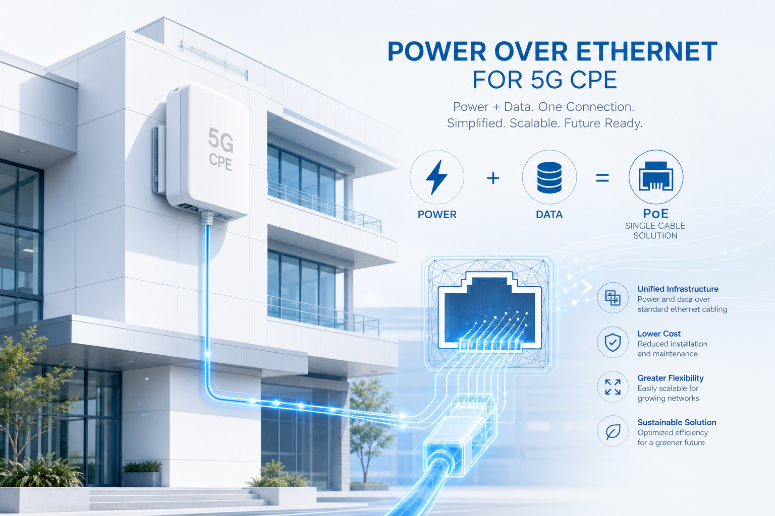
    Power over Ethernet (PoE) has evolved from a convenience feature for IP phones and cameras into a mission-critical infrastructure requirement for modern 5G Fixed Wireless Access CPE. As operators deploy outdoor and enterprise-grade CPE at scale — on rooftops, poles, building facades, and industrial sites — the ability to deliver both power and data over a single Ethernet cable dramatically reduces installation complexity, lowers total cost of ownership, and improves deployment flexibility. This guide examines the PoE architecture decisions that technical buyers must evaluate when selecting 5G CPE for large-scale FWA rollouts.

    IEEE 802.3bt Type 4: The New Baseline for 5G CPE

    The IEEE 802.3bt standard (PoE++ or 4PPoE), ratified in 2019, defines Type 3 (60W) and Type 4 (90W) power delivery over four-pair Cat6a/Cat7 cabling. For 5G CPE applications, Type 4 (90W at PSE, 71.3W guaranteed at PD over 100m) has emerged as the preferred specification for outdoor units powering high-gain antenna arrays, active beamforming modules, and multi-band RF front-ends that collectively draw 35–55W under full load.

    Key technical parameters that CPE procurement teams should verify:

    • PD Classification: The CPE should present Class 8 signature (802.3bt Type 4) during LLDP negotiation, ensuring the PSE delivers the full 90W budget. Devices misclassified as Class 4 (Type 2, 30W) will experience brownout under peak RF load.
    • Autoclass Support: Advanced CPE platforms implement Autoclass (802.3bt Annex A), which dynamically reports actual power consumption to the PSE every 30 seconds. This enables intelligent power budget management in multi-port PoE switches serving 8–24 CPE devices simultaneously.
    • Dual PD Redundancy: Carrier-grade outdoor CPE should support dual PoE inputs with automatic failover, ensuring uninterrupted operation if one PSE port or cable run fails. This is particularly critical for enterprise backhaul and public safety applications requiring five-nines availability.

    Cable Infrastructure: Cat6a Minimum, Cat7 Recommended

    Type 4 PoE at 90W pushes the thermal limits of Cat5e cabling, particularly in outdoor conduit installations exposed to direct sunlight. The DC resistance of 24AWG Cat5e (approximately 9.4Ω/100m per conductor) results in 5.8W of cable power loss at full 90W delivery, generating localized heating that accelerates insulation degradation and increases bit error rates on the data pairs.

    For outdoor 5G CPE installations, we recommend:

    • Minimum: Cat6a shielded (F/UTP or S/FTP), 23AWG solid copper, with outdoor-rated (CMX) jacket for exposed runs
    • Recommended: Cat7 S/FTP, 22AWG, with individually shielded pairs and overall braid — this provides 30% lower DC resistance than Cat6a and superior alien crosstalk rejection, which becomes significant when bundling multiple PoE cables in a single conduit riser
    • Maximum distance: 100 meters (328 feet) per 802.3bt specification, though operators deploying in high-temperature environments (ambient >40°C) should derate to 80 meters to maintain safe cable temperature margins

    Remote Power Management and Fleet Monitoring

    Enterprise and carrier CPE deployments benefit significantly from remote PoE management capabilities integrated into the device management platform. Modern 5G CPE supporting TR-369 USP (User Services Platform) can expose PoE telemetry — input voltage, current draw, PD class, and power negotiation logs — to centralized operations systems.

    Operational benefits of instrumented PoE telemetry include:

    • Predictive Maintenance: Gradual increase in current draw over weeks or months often precedes PSE or PD failure. Trend analysis across a fleet of thousands of CPE units enables proactive dispatch before service-impacting outages occur.
    • Power Budget Optimization: In dense multi-CPE installations (e.g., rooftop colocation sites), real-time per-port power monitoring prevents PSE oversubscription and enables dynamic load shedding during peak thermal conditions.
    • Installation Validation: Post-installation PoE diagnostics — cable resistance measurement, PD classification verification, and LLDP negotiation logs — provide automated quality assurance without requiring a truck roll for physical inspection.

    Surge Protection and Outdoor Hardening

    Outdoor PoE deployments introduce unique electrical safety considerations. A rooftop CPE connected via 100m Cat6a cable effectively creates a 100m antenna for induced lightning transients and ground potential differences between buildings. Technical buyers should verify that CPE devices include:

    • GDT-Based Primary Protection: Gas discharge tube surge arrestors rated for 6kV/3kA (IEC 61000-4-5 Class 4) on all four pairs at the PD input
    • Isolated PoE PD Interface: 1500VAC galvanic isolation between the PoE input and CPE logic ground, preventing ground loops in multi-building campus deployments
    • Outdoor Enclosure Rating: Minimum IP67 for the CPE enclosure with IP67-rated RJ45 connectors or hardwired cable gland terminations

    Procurement Checklist for PoE 5G CPE

    When evaluating 5G CPE with PoE for carrier-grade or enterprise deployments, technical buyers should verify the following minimum specifications:

    1. 802.3bt Type 4 (Class 8) PD compliance with 71.3W guaranteed available power
    2. Autoclass support with dynamic power reporting via LLDP
    3. Dual PD input with automatic failover (carrier-grade outdoor units)
    4. 1.5kVAC galvanic isolation between PoE input and system ground
    5. 6kV surge protection per IEC 61000-4-5 on all PoE pairs
    6. IP67 enclosure rating with outdoor-rated connector solutions
    7. TR-369 USP telemetry for remote PoE monitoring and fleet management
    8. Operating temperature range of -40°C to +65°C for outdoor deployments

    Honlly Telecom’s outdoor 5G FWA CPE series integrates 802.3bt Type 4 PoE with dual PD redundancy, comprehensive surge protection, and full TR-369 remote management — engineered for the real-world demands of carrier-scale outdoor FWA rollouts. Contact our engineering team to discuss PoE CPE specifications tailored to your deployment environment.

  • A Technical Buyer’s Guide to 5G CPE for Multi-Dwelling Units (MDUs): Distributed Antenna Systems, Indoor Coverage Optimization, Inter-Unit Interference Management, and Multi-Tenant FWA Deployment Architecture

    A Technical Buyer’s Guide to 5G CPE for Multi-Dwelling Units (MDUs): Distributed Antenna Systems, Indoor Coverage Optimization, Inter-Unit Interference Management, and Multi-Tenant FWA Deployment Architecture

    Multi-Dwelling Units (MDUs) — apartment buildings, condominiums, student housing, and mixed-use developments — represent one of the largest untapped addressable markets for 5G Fixed Wireless Access. Yet MDU deployments present unique RF propagation, interference management, and service demarcation challenges that differ fundamentally from single-family home installations. This guide provides technical buyers and operator planning teams with a structured framework for evaluating 5G CPE solutions purpose-built for multi-tenant environments.

    The MDU Signal Challenge: Building Penetration Loss

    Modern MDU construction materials impose significant RF attenuation that single-family CPE designs cannot reliably overcome. Low-emissivity (Low-E) coated windows — standard in energy-efficient buildings constructed after 2015 — attenuate mid-band 5G signals (3.5GHz n78) by 22–32dB, effectively reducing outdoor-to-indoor signal strength by 99.4–99.9%. Reinforced concrete floor slabs add 15–25dB per floor, while metal-framed curtain wall systems create unpredictable multipath and polarization distortion.

    For operators deploying FWA services to MDU residents, the critical metrics are:

    • Median RSRP at Window Position: Target ≥ -105 dBm for reliable 100Mbps+ service using 4×4 MIMO CPE with 6dBi integrated antennas
    • Building Entry Loss (BEL): Measured difference between outdoor RSRP and indoor RSRP at 1m from the window — BEL exceeding 15dB typically requires external antenna solutions
    • Floor-to-Floor Signal Variation: In buildings exceeding 6 stories, upper-floor units often experience 8–12dB stronger signals than ground-floor units due to reduced ground clutter and clearer line-of-sight to macro sites

    Distributed Antenna Architecture for MDUs

    For MDUs with high BEL or deep units where window-placed CPE cannot provide adequate whole-unit coverage, a distributed antenna system (DAS) architecture offers a scalable solution. In this configuration, an externally mounted donor antenna (typically a high-gain panel or log-periodic antenna on the rooftop or balcony) connects via low-loss coaxial cable to an indoor CPE unit placed centrally in the apartment.

    Key design parameters for MDU distributed antenna deployments:

    • Donor Antenna Gain: 8–11 dBi directional panel antenna with ±45° beamwidth, mounted with clear line-of-sight to the serving gNodeB sector
    • Cable Loss Budget: For cable runs up to 20m, LMR-400 equivalent (0.22 dB/m at 3.5GHz) limits total cable loss to 4.4dB — acceptable when paired with an 11dBi donor antenna yielding net 6.6dBi system gain. For runs exceeding 20m, 1/2-inch Heliax (0.13 dB/m) is recommended
    • CPE Antenna Port Configuration: The indoor CPE unit must support external antenna ports (SMA or TS-9 connectors) with automatic detection and switching between internal and external antenna paths

    Inter-Unit Interference Management

    In high-density MDU deployments where 20–50 units per floor may each operate a 5G CPE with integrated Wi-Fi 6/6E access point, co-channel and adjacent-channel interference becomes a significant performance degrader. Technical buyers should evaluate CPE platforms that incorporate:

    • Automatic Channel Selection (ACS): Wi-Fi radio management that continuously scans the 2.4GHz, 5GHz, and 6GHz bands and selects the least-congested channel based on both Wi-Fi and non-Wi-Fi interference sources
    • Transmit Power Control (TPC): Dynamic adjustment of Wi-Fi TX power based on apartment size — a studio apartment requires significantly less power than a three-bedroom unit, and excessive power only increases neighbor interference
    • DFS Channel Utilization: Aggressive use of DFS (Dynamic Frequency Selection) channels in the 5GHz band (channels 52–144), which tend to be underutilized in MDU environments due to consumer router default configurations avoiding them
    • 5G NR Interference Coordination: CPE supporting 5G NR-U (NR in unlicensed spectrum) or NR-based sidelink can coordinate with neighboring CPE units to avoid mutual interference on the 5G access link itself

    Multi-Tenant Service Demarcation and Management

    MDU deployments require clear service demarcation between the operator’s responsibility (the CPE and its WAN connection) and the resident’s domain (the LAN/Wi-Fi network). Enterprise-grade CPE platforms address this through:

    • Dual-SSID Architecture: A carrier-managed SSID (for performance monitoring, firmware updates, and QoS enforcement) alongside a resident-managed SSID with self-service portal for password changes and parental controls
    • Per-Tenant VLAN Tagging: 802.1Q VLAN isolation between units sharing common building infrastructure such as rooftop antenna systems or basement PoE switch aggregation, ensuring traffic separation and security between tenants
    • Bulk Provisioning API: TR-369 USP or TR-069 CWMP support for zero-touch provisioning of hundreds of CPE units simultaneously, with pre-configured tenant profiles mapping to building, floor, and unit identifiers

    Procurement Recommendations for MDU-Scale Deployments

    Technical buyers procuring 5G CPE for MDU deployments should prioritize the following specifications:

    1. External Antenna Support: SMA or TS-9 ports for optional external donor antenna connection, with automatic internal/external antenna path switching
    2. Wi-Fi 6E or Wi-Fi 7: 6GHz band support dramatically reduces intra-MDU interference by accessing 1200MHz of new, uncongested spectrum not available in 2.4/5GHz-only devices
    3. Per-Unit Power Budget ≤ 15W: Minimizes heat generation in enclosed spaces and enables PoE-powered operation from a centralized building switch
    4. TR-369 USP with Bulk Provisioning: Essential for operators deploying CPE at scale across hundreds to thousands of MDU units
    5. Multi-Language Self-Service Portal: Critical for MDUs serving international residents who may not be fluent in the operator’s primary language

    Honlly Telecom’s 5G FWA CPE portfolio includes MDU-optimized configurations with external antenna support, Wi-Fi 6E/7 integrated radios with advanced interference management, and TR-369 USP-based fleet orchestration — purpose-built for the unique demands of multi-tenant fixed wireless deployments. Contact our solutions engineering team to discuss MDU CPE configurations matched to your building typology and subscriber density requirements.

  • 5G CPE Carrier Aggregation Advances Drive Multi-Gigabit FWA Performance as Operators Leverage Sub-6GHz Spectrum Assets for Enterprise Broadband in 2026

    5G CPE Carrier Aggregation Advances Drive Multi-Gigabit FWA Performance as Operators Leverage Sub-6GHz Spectrum Assets for Enterprise Broadband in 2026

    The global 5G Fixed Wireless Access (FWA) market is entering a new performance tier in 2026 as carrier aggregation (CA) technology matures across sub-6GHz spectrum bands. With 3GPP Release 17 and 18 enhancements now reaching commercial CPE silicon, operators are leveraging multi-component carrier aggregation to deliver sustained multi-gigabit throughput without millimeter-wave infrastructure — a development that fundamentally reshapes the economics of high-speed FWA deployment.

    The Carrier Aggregation Advantage in FWA CPE

    Carrier aggregation combines multiple frequency blocks — typically two to four component carriers across n77 (3.7GHz), n78 (3.5GHz), and n41 (2.5GHz) bands — into a single logical data pipe. Modern 5G CPE platforms supporting 4CC CA (four-component carrier aggregation) can achieve theoretical downlink peaks exceeding 4 Gbps using sub-6GHz spectrum alone, eliminating the coverage and penetration limitations that have constrained mmWave FWA rollouts.

    Qualcomm’s Snapdragon X75 and MediaTek’s T830 platforms, both shipping in volume CPE devices throughout 2026, support up to 4x downlink CA with 256QAM modulation. This means operators can aggregate fragmented mid-band spectrum holdings — a common scenario in markets where 5G spectrum was auctioned in smaller blocks — into commercially viable FWA bandwidth tiers that compete directly with fiber-to-the-home (FTTH) services.

    Real-World Throughput: Beyond Lab Benchmarks

    Field trials conducted across Southeast Asian and Middle Eastern operator networks in Q2 2026 demonstrate that 3CC CA configurations (e.g., 100MHz n78 + 80MHz n78 + 50MHz n41) consistently deliver 1.8–2.4 Gbps downlink in suburban deployment scenarios with standard 4×4 MIMO CPE antennas. In optimal conditions, 4CC CA setups have recorded sustained 3.5 Gbps throughput at distances up to 2.5km from the gNodeB.

    These real-world figures represent a 2–3× throughput improvement over single-carrier 5G CPE deployments from 2024–2025, making carrier-aggregated FWA a credible alternative to gigabit cable and fiber for the first time at scale. For operators, the economic calculus is compelling: CA-enabled CPE carries a modest BOM cost premium of approximately $8–12 per unit while unlocking service tiers that command $15–25 higher monthly ARPU.

    Inter-Band CA and Spectrum Fragmentation Strategy

    A particularly significant development in 2026 is the growing adoption of inter-band CA combining TDD and FDD spectrum. Operators with legacy FDD holdings (n1, n3, n28) are aggregating these with TDD mid-band (n78) to improve uplink performance — a critical factor for enterprise FWA use cases involving video conferencing, cloud upload, and IoT telemetry backhaul. Supplementary uplink (SUL) configurations, where n78 downlink is paired with n80/n84 uplink, are also entering commercial CPE firmware.

    For B2B buyers and operator procurement teams, the key takeaway is that CPE devices supporting at least 3CC CA with inter-band TDD+FDD capability represent the minimum viable specification for future-proof FWA deployments through 2028. Devices limited to 2CC or single-band operation will face early obsolescence as operators densify their mid-band networks and aggregate additional carriers.

    Power Efficiency and Thermal Considerations

    The increased RF complexity of multi-carrier aggregation introduces new thermal design challenges. 4CC CA modems draw approximately 15–20% more power than equivalent single-carrier configurations, requiring enhanced passive cooling solutions in CPE enclosures. Leading CPE OEMs are addressing this through advanced heat spreader materials, optimized PCB layout for thermal dissipation, and intelligent carrier management firmware that dynamically scales CA configuration based on throughput demand and thermal headroom — reducing component carrier count during low-traffic periods to conserve energy.

    Procurement Outlook for H2 2026–2027

    As 5G-Advanced (3GPP Release 18) networks go live across Asia-Pacific, Europe, and North America, carrier aggregation will transition from a differentiating feature to a baseline requirement. The GSMA estimates that by Q4 2027, over 65% of new FWA CPE shipments will support 3CC CA or higher. For operators planning FWA service expansions, prioritizing CA-capable CPE in current RFPs is not merely a performance decision — it is a strategic investment in spectrum asset utilization, service tier differentiation, and long-term network efficiency.

    At Honlly Telecom, our 5G FWA CPE portfolio is engineered with carrier aggregation at its core. From 3CC CA-enabled indoor CPE for residential and SMB fixed wireless to 4CC CA industrial-grade outdoor units for enterprise backhaul, our devices are designed for the multi-carrier reality of modern 5G networks. Contact our solutions team to discuss CA-capable CPE tailored to your spectrum strategy and deployment scenario.