Author: openclaw-Lisa-New

  • Thermal Design for Outdoor 5G CPE: Engineering IP67-Rated Enclosures for Extreme Climate Deployments

    Thermal Design for Outdoor 5G CPE: Engineering IP67-Rated Enclosures for Extreme Climate Deployments

    Introduction: Why Outdoor CPE Thermal Design Matters

    Outdoor 5G CPE devices face some of the harshest operating conditions in telecom infrastructure. Mounted on rooftops, poles, and building exteriors, these devices must maintain reliable performance across temperature extremes from -40°C desert nights to +55°C direct sunlight — all while dissipating heat from power-hungry 5G chipsets. Effective thermal management is not optional — it is the difference between a 5-year field life and a 6-month failure rate.

    This engineering guide examines the thermal design principles, materials, and testing protocols that ensure outdoor 5G CPE achieves IP67-rated protection while maintaining safe operating temperatures for internal components.

    Understanding the Thermal Challenge in 5G Outdoor CPE

    5G NR CPE devices generate significantly more heat than their 4G predecessors. The combination of multi-gigabit throughput, carrier aggregation across multiple bands, and beamforming antenna arrays pushes power consumption to 15–30W — comparable to a small laptop. In a sealed IP67 enclosure with no active fan, this heat has nowhere to go except through passive conduction and radiation.

    Key Heat Sources in Outdoor 5G CPE

    • 5G modem/baseband processor: 4–8W for sub-6 GHz; up to 12W for mmWave-capable chipsets
    • RF front-end and power amplifiers: 3–6W depending on TX power and number of antenna chains
    • WiFi 6/7 subsystem: 2–4W for dual-band concurrent operation
    • Ethernet PHY and PoE PD controller: 1–2W
    • Total thermal budget: 12–25W for typical outdoor 5G CPE

    IP67 Enclosure Requirements and Thermal Trade-offs

    IP67 certification requires complete protection against dust ingress (6) and immersion in 1 meter of water for 30 minutes (7). This means the enclosure must be hermetically sealed — no ventilation holes, no fans, no air exchange with the outside environment. Every watt of heat generated must be transferred through the enclosure walls via conduction.

    The fundamental trade-off: better sealing = worse natural cooling. Solving this requires careful material selection and enclosure geometry optimization.

    Passive Cooling Design Strategies

    1. Conductive Heat Path Optimization

    Direct thermal contact between high-power components and the enclosure body is the most efficient passive cooling method. Thermal interface materials (TIM) — typically silicone-based gap fillers with 3–6 W/mK conductivity — bridge the air gap between chip surfaces and the aluminum heatsink or enclosure wall. For 5G CPE, a 0.5–1.0 mm gap filler compressed to 30% provides optimal thermal transfer without stressing solder joints.

    2. Aluminum Die-Cast Enclosure with Integrated Fins

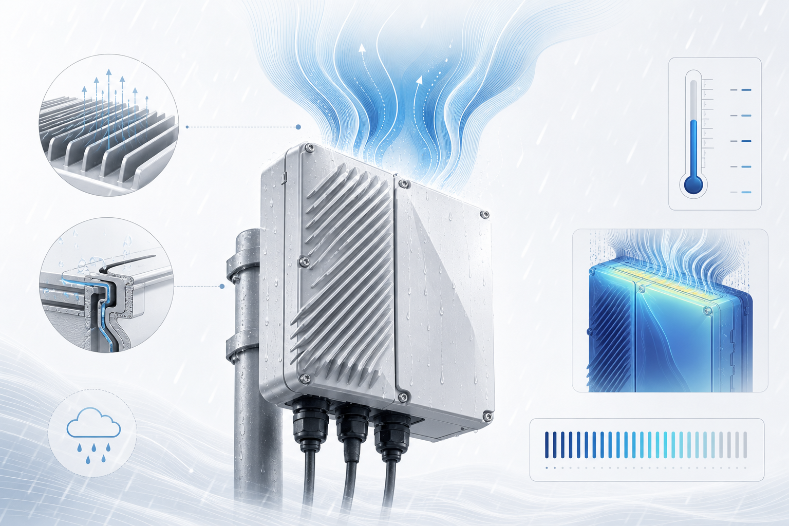
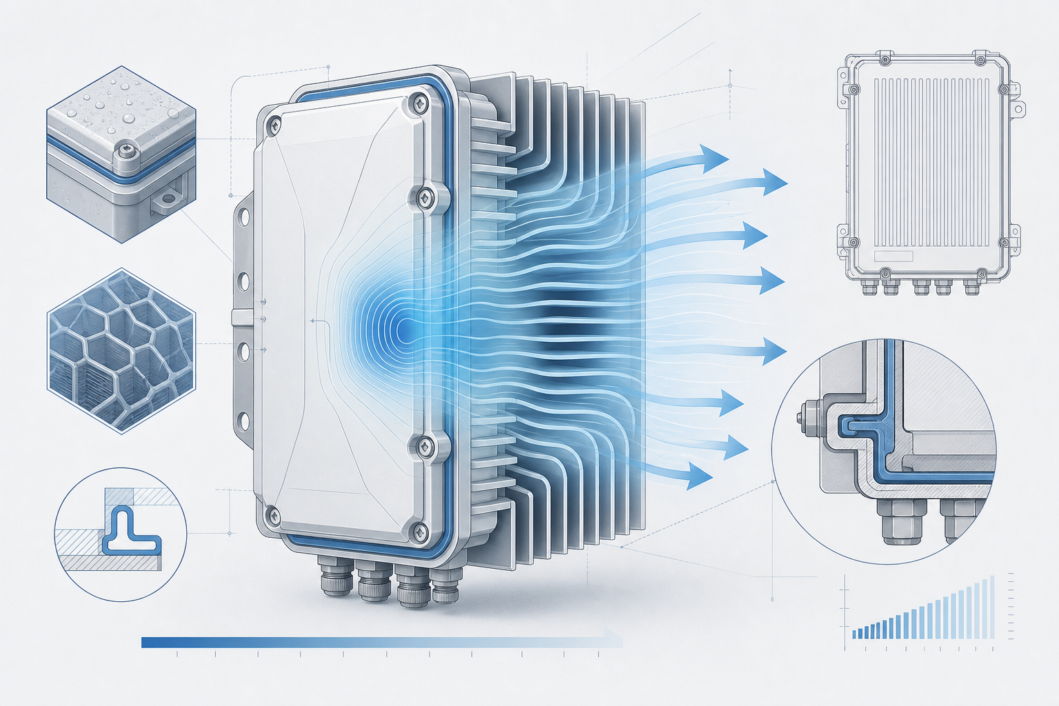
    Die-cast aluminum (ADC12 or A380 alloy) is the material of choice for outdoor CPE enclosures. Its thermal conductivity (96–130 W/mK) is 100× higher than plastic alternatives. External cooling fins increase surface area by 300–500%, dramatically improving convective heat transfer to ambient air. Modern designs use computational fluid dynamics (CFD) simulation to optimize fin spacing, height, and orientation for maximum natural convection at the target wind speeds for the deployment region.

    3. Phase-Change Materials for Peak Load Buffering

    For deployments in regions with extreme daily temperature swings, paraffin-based phase-change materials (PCMs) embedded in the enclosure wall can absorb heat during peak afternoon operation and release it during cooler evening hours. This thermal buffering smooths temperature peaks by 8–15°C, extending component lifespan without adding active cooling complexity.

    Testing and Validation: Beyond the Datasheet

    Real-world thermal validation goes far beyond component datasheet specifications. Reputable CPE manufacturers conduct:

    • Thermal chamber cycling: -40°C to +85°C, 500+ cycles, monitoring LTE/5G throughput stability
    • Solar load testing: 1,120 W/m² simulated solar radiation at 55°C ambient, 8-hour duration
    • Condensation testing: Rapid temperature transitions (85°C to -40°C in 15 seconds) to verify no internal moisture accumulation
    • Accelerated life testing: Continuous operation at 85°C component junction temperature for 1,000+ hours

    FAQ

    Q: Can outdoor CPE use active cooling (fans)?
    A: Not in IP67-rated enclosures. Active cooling requires air intake/exhaust, which breaks the dust and water seal. All cooling must be passive. Some industrial designs use sealed liquid cooling loops, but these add cost and complexity rarely justified for CPE.

    Q: How does solar radiation affect thermal performance?
    A: Direct sunlight adds 500–1,120 W/m² of radiative heat load to the enclosure surface. Light-colored (white or light gray) enclosures with high solar reflectance (>0.85) reduce solar absorption by 40–60% compared to dark-colored units.

    Q: What is the typical operating temperature range for outdoor 5G CPE?
    A: Industrial-grade designs achieve -40°C to +60°C ambient operation with full RF performance. Extended-temperature variants push to +70°C with graceful performance throttling above 55°C.

    Conclusion

    Thermal design is the silent differentiator between outdoor 5G CPE that survives a decade in the field and units that fail within the first summer. When evaluating CPE suppliers, buyers should request full thermal validation reports — not just spec sheets — and prioritize manufacturers with in-house environmental testing laboratories and proven field-deployment track records in target climate zones.

    Contact Honlly Telecom to discuss outdoor 5G CPE with validated IP67 thermal designs for your deployment region — backed by ISO 9001 manufacturing and full environmental test reports.

  • eSIM Integration in CPE: Provisioning Architecture and Recovery

    eSIM Integration in CPE: Provisioning Architecture and Recovery

    Remote SIM provisioning can change how a CPE receives and manages an operator profile. It does not remove the need to qualify the radio hardware, network service and provisioning infrastructure together. A useful integration plan identifies each component and the recovery path before the device is shipped.

    Select an architecture before selecting components

    GSMA publishes different remote SIM provisioning specifications for M2M, consumer and IoT use cases. SGP.22 describes consumer technical requirements, while SGP.32 addresses the IoT architecture. Do not mix components or certification statements from these families without confirming how the proposed implementation works.

    Record the eUICC, relevant software, supported specification versions, profile provider and operator service. An embedded package and the ability to download profiles are separate implementation details. The full design must support the intended workflow.

    Map the first connection

    Explain how a new device obtains connectivity before the target profile is active. Identify who owns bootstrap credentials, whether the workflow requires a user action and what occurs if the initial download fails. A design that works on a development bench may need additional preparation for an unattended field installation.

    Define profile lifecycle operations

    • Who can authorize a download, activation, deactivation or deletion?
    • How are device identities associated with the correct customer account?
    • Which operations require connectivity through the currently active profile?
    • What happens if power fails or the device loses service during an operation?
    • How will a returned device be cleared and reassigned without exposing previous credentials?

    Prove recovery before volume deployment

    Build test cases for invalid activation details, interrupted downloads, unavailable profile services and operator migration. Keep test credentials outside public logs. Demonstrate the documented recovery route using the actual production-intended hardware and firmware. Do not assume that storing multiple profiles means two services can be active at the same time.

    Keep radio qualification in scope

    Switching a profile cannot add missing cellular bands, modem features or local approvals. A global provisioning workflow may still need different radio variants and local service agreements. Separate provisioning integration from claims of worldwide operator compatibility.

    Agree the handover package

    Request an architecture diagram, supported version list, workflow documentation, security responsibilities and acceptance-test results. Specify who supports the eUICC, device software and connectivity service. Compare physical SIM and eSIM options against the actual operating process rather than assuming one is always cheaper or easier.

    Related product and planning resources

    Sources and further reading

  • Private 5G (NPN) Deployments Accelerate in 2026: CPE Requirements for Enterprise Industrial Networks

    Private 5G (NPN) Deployments Accelerate in 2026: CPE Requirements for Enterprise Industrial Networks

    Private 5G — formally defined in 3GPP as Non-Public Network (NPN) — is moving from pilot projects to production deployments across manufacturing, logistics, mining, and utilities in 2026. According to industry analysts, the global private 5G market is projected to exceed USD 12 billion by 2027, driven by enterprises seeking deterministic wireless connectivity that Wi-Fi cannot deliver in demanding industrial environments.

    The 2026 Acceleration: What’s Driving It

    Three trends are converging in 2026 to accelerate NPN adoption:

    • Spectrum availability: Regulators in Germany (3.7\u20133.8 GHz), the UK (n77 band), Japan (4.6\u20134.9 GHz), and the US (CBRS 3.55\u20133.7 GHz) now offer dedicated enterprise spectrum, removing the dependency on mobile operator partnerships for private deployments.
    • Device ecosystem maturity: Qualcomm, MediaTek, and UNISOC now offer chipsets with native NPN support, meaning CPE vendors can deliver NPN-capable devices without expensive customization.
    • Industry 4.0 ROI cases: Early adopters in automotive manufacturing and logistics are reporting measurable outcomes — 30\u201350% reduction in production line reconfiguration time, sub-10 ms latency for AGV (Automated Guided Vehicle) control, and 99.999% reliability in harsh RF environments.

    What NPN Means for CPE Requirements

    Enterprise-grade NPN CPE must meet requirements that differ significantly from consumer or even standard carrier-grade devices:

    • Standalone NPN (SNPN) support: The CPE must operate on an isolated 5G core without connecting to a public network. This requires SNPN-capable firmware with support for Network Identifier (NID) and manual PLMN selection restricted to the enterprise designated network.
    • URLLC (Ultra-Reliable Low-Latency Communication): For industrial control applications, the CPE must support 3GPP Release 16/17 URLLC features including mini-slot scheduling, configured grant transmission, and PDCP duplication — delivering consistent sub-10 ms latency.
    • Time-Sensitive Networking (TSN) integration: In factory environments, 5G must interwork with existing IEEE 802.1 TSN Ethernet infrastructure. NPN CPE acting as a TSN bridge requires 5G-to-TSN translator functionality and support for IEEE 802.1AS timing synchronization.
    • Industrial protocol compatibility: The CPE Ethernet interface should support PROFINET, EtherCAT, and Modbus TCP pass-through without packet loss or timing jitter that industrial controllers would reject.
    • Ruggedized form factor: Unlike office CPE, industrial NPN devices operate on factory floors with vibration, dust, and temperature swings. DIN-rail mounting, IP40+ ingress protection, and extended temperature range (\u221220\u00b0C to +60\u00b0C) are baseline requirements.

    System Integrator Considerations

    For system integrators designing NPN solutions, CPE selection should prioritize three factors:

    1. Certified interoperability: The CPE must be tested against the specific 5G core (Ericsson, Nokia, Druid, or open-source platforms like free5GC) and RAN (small cell or distributed antenna system) chosen for the deployment. Interoperability gaps discovered during commissioning are expensive to fix.

    2. Centralized device management: NPN deployments often span multiple factory sites with hundreds of CPE units each. TR-369 USP or SNMP-based remote management, zero-touch provisioning, and firmware-over-the-air (FOTA) update capability are essential for ongoing operations.

    3. Security certification: Industrial NPNs carry higher security requirements than public networks. CPE should support SIM-based authentication (SUCI encryption), IPsec tunnel termination, and ideally, compliance with IEC 62443 for industrial control system security.

    Outlook

    As NPN spectrum becomes available in more markets and the CPE ecosystem matures, enterprises have a growing window of opportunity to deploy private 5G for use cases that Wi-Fi 6E/7 cannot reliably serve. The CPE — as the network edge device connecting machines, sensors, and controllers — will play a defining role in whether these deployments deliver on their performance and reliability promises.

    FAQ

    What is the difference between SNPN and PNI-NPN?

    SNPN (Standalone NPN) operates a completely independent 5G network with its own core and RAN, identified by a unique NID. PNI-NPN (Public Network Integrated NPN) is a private slice within a public operator network, identified by a CAG (Closed Access Group) ID. CPE for SNPN must support NID-based network selection, which is not required for PNI-NPN.

    Can existing 5G CPE be firmware-upgraded for NPN?

    Some existing 5G CPE with 3GPP Release 16+ chipsets can add SNPN support through firmware updates. However, URLLC and TSN features require hardware-level support in the modem — a firmware update alone cannot add them if the baseband was designed for Release 15 eMBB only.

    Planning a private 5G NPN deployment? Contact Honlly Telecom to discuss NPN-capable CPE requirements and explore our industrial-grade 5G device portfolio.

  • Outdoor 5G CPE Thermal Design: Sealing and Sustained Performance

    Outdoor 5G CPE Thermal Design: Sealing and Sustained Performance

    Outdoor 5G CPE must keep its radio, processor and power circuitry within their operating limits while protecting connectors and electronics from the installation environment. An enclosure’s IP rating and its thermal performance describe different properties. Check both before selecting a device for a rooftop, exterior wall or pole.

    Start with the actual installation

    Document the mounting position, shade, expected ambient conditions, cable route and service access. Direct sun, adjacent hot equipment and restricted airflow can change the enclosure’s heat balance. A temperature range on a datasheet does not by itself show the throughput or transmit power a device sustains throughout that range.

    Ask for the exact enclosure, modem, power supply and firmware tested. An evaluation of one enclosure or board revision should not automatically be applied to another. Define the expected duty cycle: occasional downloads, continuous uplink video and prolonged bidirectional traffic create different operating conditions.

    Understand the heat path

    A design review should trace heat from the active components through interface materials, spreaders and enclosure surfaces to the surrounding air. Inspect how assembly tolerances and mounting pressure affect thermal contact. External fins, mounting brackets and solar shields need to be evaluated in the intended orientation.

    Metal and plastic housings create different mechanical, thermal and radio design constraints. Neither material alone proves sustained performance. Ask how internal antennas, sealing, weight and the service procedure were considered alongside heat transfer.

    Keep ingress protection separate from temperature qualification

    IEC 60529 defines enclosure ingress-protection classifications. An IP marking is not a certificate of thermal endurance, UV resistance, corrosion resistance or immunity to condensation. Request the applicable enclosure test documentation and installation instructions, including the connectors, glands and caps required to maintain the stated protection.

    The HL-6300R product page lists an IP65 outdoor unit. This general engineering guide does not upgrade that model to IP67 or establish performance outside its published limits. Use the specific model’s current datasheet and installation instructions.

    Build a repeatable acceptance test

    1. Record the device revision, firmware, enclosure configuration, mounting orientation and power equipment.
    2. Choose ambient and solar-exposure conditions that represent the project, within agreed operating limits.
    3. Run the expected uplink and downlink workload. Log throughput, latency, packet loss, supply behaviour and available temperature telemetry.
    4. Observe whether thermal controls reduce performance or trigger restarts. Record the recovery behaviour when the load or temperature falls.
    5. Repeat the test with the installation accessories fitted. Recheck sealing after any approved servicing procedure.

    Agree pass/fail criteria with the supplier before testing. Do not substitute an arbitrary universal temperature or a short peak-speed result for evidence of sustained service. For exposed installations, have a qualified installer assess mounting, bonding and surge protection under the applicable local requirements.

    What to include in a supplier request

    Send the installation environment, expected traffic profile, operator requirements and service-access constraints. Request model-specific operating limits, available test evidence and any restrictions on installation orientation or accessory selection. A quotation should identify the evaluated hardware and firmware configuration.

    Related product and planning resources

    Sources and further reading

  • eSIM Integration in 4G/5G CPE: Simplifying Global Operator Deployment and Logistics

    eSIM Integration in 4G/5G CPE: Simplifying Global Operator Deployment and Logistics

    For telecom operators and ISPs managing multi-country CPE deployments, SIM logistics have long been a cost bottleneck. Physical SIM cards require country-specific inventory, manual provisioning, and in-field replacement when roaming agreements change — each step multiplying operational overhead. eSIM technology, now maturing across 4G and 5G CPE platforms, changes this equation fundamentally.

    What eSIM Means for CPE Deployment

    An embedded SIM (eSIM) is a soldered, remotely programmable SIM chip compliant with GSMA’s Remote SIM Provisioning (RSP) specifications. Unlike a traditional plastic SIM that binds a device to one operator profile, an eSIM-enabled CPE can store multiple operator profiles and switch between them over the air — without a technician visit or hardware swap.

    For CPE devices deployed across borders, this capability removes the need to stock SKU variants per operator. One hardware SKU can serve deployments in Germany, Brazil, and Indonesia — the operator profile is loaded after the device arrives at its destination.

    Supply Chain Simplification: One SKU, Global Reach

    In a traditional physical SIM model, an operator or distributor must:

    • Forecast demand per country and per operator partner
    • Procure CPE units pre-loaded with country-specific SIM cards
    • Manage separate inventory pools for each market
    • Handle returns and re-flashing when forecasts miss

    With eSIM, the procurement team orders a single CPE variant. The device ships to any regional warehouse, and the correct operator profile is downloaded during first boot or at a staging facility. This collapses SKU count, reduces warehousing complexity, and cuts the cost of demand-forecast errors dramatically.

    Remote SIM Provisioning: How It Works

    GSMA’s RSP architecture defines two core components: the SM-DP+ (Subscription Manager Data Preparation) server, managed by the operator or a third-party RSP platform, and the eUICC (embedded UICC) inside the CPE. The provisioning flow is straightforward:

    1. Profile download: The CPE connects to any available network (including a bootstrap profile) and contacts the SM-DP+ server.
    2. Mutual authentication: The SM-DP+ verifies the eUICC certificate and the eUICC authenticates the server.
    3. Profile installation: The operator profile — containing IMSI, authentication keys, and network parameters — is encrypted and installed on the eUICC.
    4. Profile activation: The CPE switches to the new profile and attaches to the target operator’s network.

    This entire process can be triggered remotely, at scale, and without physical access to the device. For operators managing tens of thousands of CPE units across multiple markets, the operational savings are substantial.

    Multi-Operator Switching: Reducing Roaming Costs

    An eSIM-capable CPE can hold multiple operator profiles simultaneously (typically 5\u201310, depending on eUICC memory). Combined with intelligent profile switching logic, the CPE can:

    • Select the lowest-cost operator for data based on time-of-day or usage thresholds
    • Fail over to a second operator when the primary network degrades
    • Switch profiles based on geographic location (detected via network MCC/MNC)

    This multi-IMSI capability is especially valuable for IoT and enterprise CPE use cases where devices move between regions or require guaranteed uptime. It also gives operators flexibility to renegotiate roaming agreements without touching deployed hardware.

    Key Considerations for CPE Procurement

    When evaluating eSIM-capable 4G/5G CPE for operator deployment, procurement teams should verify:

    • GSMA SGP.02 / SGP.22 compliance: Ensure the eUICC supports the M2M (SGP.02) or consumer (SGP.22) RSP architecture appropriate for the deployment model.
    • Profile memory capacity: Confirm how many operator profiles the eUICC can store and whether profile deletion/replacement is supported OTA.
    • Bootstrap connectivity: Understand how the CPE gains initial network access to download its first operational profile — bootstrap IMSI, Wi-Fi provisioning, or local staging tool.
    • SM-DP+ integration: Verify that your chosen RSP platform or operator SM-DP+ is compatible with the CPE vendor’s eUICC implementation.
    • Regulatory compliance: Some markets restrict permanent roaming or require local IMSI registration. eSIM simplifies compliance by enabling local profile provisioning.

    The Logistics Advantage: Real-World Impact

    Consider a European MVNO expanding to three new markets in Southeast Asia. With physical SIMs, the roll-out requires three separate CPE shipments, three inventory pools, and on-site technicians for installation. With eSIM-capable CPE, a single shipment covers all three markets. Devices are activated remotely after customs clearance, and the operator can provision local profiles from a central NOC. Deployment time shrinks from months to days.

    For fixed wireless access (FWA) deployments at scale — where CPE installation is already a major cost driver — eliminating the SIM-handling step reduces truck rolls, simplifies installer training, and accelerates time-to-revenue.

    FAQ

    Does eSIM increase CPE hardware cost?

    The eUICC chip adds a marginal component cost — typically under USD 1 per unit at volume. This is offset many times over by supply chain simplification and reduced SIM logistics expense. Most CPE vendors now offer eSIM as a standard or optional feature with negligible price impact.

    Can eSIM CPE fall back to a physical SIM?

    Many eSIM-capable CPE designs include both an eUICC and a physical SIM slot (hybrid configuration). This gives operators flexibility: use eSIM for primary deployment and the physical SIM slot for local testing or emergency fallback.

    What happens if the provisioning server is unreachable?

    Once a profile is installed on the eUICC, the CPE operates independently of the SM-DP+. The provisioning server is needed only during initial profile download or profile updates. If the server is unreachable at first boot, the CPE typically retries or falls back to a pre-loaded bootstrap profile.

    Is eSIM secure for operator credentials?

    Yes. The GSMA Security Accreditation Scheme (SAS) certifies eUICC manufacturing sites and SM-DP+ platforms. Profile data is encrypted end-to-end using the eUICC unique private key, which never leaves the secure element. The security model is more robust than a removable physical SIM.

    Looking for eSIM-ready 4G/5G CPE for your operator deployment? Contact Honlly Telecom to discuss your requirements and explore our CPE portfolio with integrated eSIM support.

  • 4×4 MIMO and Beamforming: A 5G CPE Antenna Evaluation Guide

    4×4 MIMO and Beamforming: A 5G CPE Antenna Evaluation Guide

    A 4×4 MIMO label describes an antenna and radio capability, not a guaranteed number of active data streams. When comparing 5G CPE, examine the complete radio implementation, supported bands and behaviour on the intended network.

    Separate spatial multiplexing and beamforming

    Spatial multiplexing carries different data streams using the same time and frequency resources. Beamforming directs radio energy through coordinated antenna operation. Both can contribute to a network’s performance, but the terms are not interchangeable. A base station’s large antenna array also does not establish the number of receive branches or supported layers in a customer device.

    Available throughput depends on bandwidth, channel conditions, network scheduling and the device implementation. Four receive branches do not guarantee twice the service speed of a two-branch device. Check whether the listed capability applies to downlink or uplink, LTE or NR, and which bands and combinations are covered.

    Ask for the antenna evidence

    • Coverage: the supported frequency ranges and the antenna configuration for each required band.
    • Radiated measurements: available efficiency, patterns and complete-device transmit/receive measurements with their test conditions.
    • Coupling and correlation: measurements across relevant frequencies and mounting conditions rather than one headline number.
    • External connections: connector type, supported bands, routing to radio branches and approved antenna options.
    • Software: any configuration required to select internal or external antenna paths.

    Read isolation values consistently

    Reports may express isolation as a positive attenuation or show transmission coupling as a negative S-parameter in dB. These conventions must be distinguished. For a coupling measurement, a more negative value means less coupled power. Ask the supplier to identify the ports, measurement convention, frequency range and acceptance criteria. An unexplained threshold is not a substitute for a complete antenna assessment.

    Compare devices under controlled conditions

    1. Use the same operator service and document SIM policy, firmware and test-client capabilities.
    2. Record the serving cell, bands, bandwidth and carrier aggregation where the device exposes them.
    3. Repeat uplink, downlink and latency measurements across representative locations and busy periods.
    4. Change orientation and placement systematically. Log signal quality, observed layers where available and disconnections.
    5. Repeat any external-antenna test with the actual cable and connectors, accounting for installation losses.

    A better result in one speed test does not identify its cause. Differences may reflect scheduling, band selection, software or the local channel. Retain the raw observations and compare distributions instead of selecting only the fastest run.

    Choose the installation format

    Compare an indoor unit at its intended location with an outdoor receiving solution when building penetration or placement constraints are significant. Outdoor mounting introduces its own power, cabling and environmental requirements. Do not select antenna gain from distance alone or infer an operator approval from band overlap.

    Use the HL-850UE and HL-6300R specification pages as model references. Confirm MIMO capability on the exact bands and ordered configuration before treating either as an approved project solution.

    Related product and planning resources

    Sources and further reading

  • CPE OEM and ODM Partner Evaluation: An Evidence-Based Playbook

    CPE OEM and ODM Partner Evaluation: An Evidence-Based Playbook

    Choose a CPE manufacturing partner by testing the ability to deliver the agreed device and maintain it through its lifecycle. Use the same written brief for candidates so that differences in scope, configuration and support remain visible.

    Fourteen questions for supplier qualification

    1. Engineering ownership: who owns radio, firmware, enclosure and test decisions, including outsourced work?
    2. Reference configuration: what exact hardware and firmware are offered for evaluation?
    3. Network qualification: which operator requirements and test scenarios have been demonstrated?
    4. Approval evidence: do the relevant documents identify the intended model, configuration, holder and scope?
    5. Production control: how are versions, traceability, calibration and assembly instructions controlled?
    6. Acceptance testing: what measurable checks distinguish an approved sample from a production lot?
    7. Change management: what notification and requalification process applies to component or software substitutions?
    8. Firmware support: how are updates, recovery and security issues handled?
    9. Customization scope: which branding, interface, packaging and software work is included?
    10. Project coordination: who approves specifications, milestones and changes?
    11. Supply planning: what quantities, dependencies and lead-time assumptions are covered by the current quotation?
    12. Commercial responsibilities: what tooling, licensing and support costs are separate from the unit price?
    13. Returns and field support: how are faults investigated and replacement arrangements documented?
    14. End-of-life planning: what notification, last-order and software-maintenance commitments are agreed?

    Use documents and demonstrations together

    Request a configuration-controlled sample, relevant reports and a test session that exercises important requirements. Staff headcount or a factory photograph is not a universal proxy for product quality. An organisation-level certificate does not establish every device’s approval.

    Release work in stages

    Separate requirements review, engineering sample, pilot deployment and production acceptance. Name the evidence and approval owner for each stage. Keep deviations visible and obtain agreement before a different component or firmware build is shipped.

    Prepare a comparable quotation request

    Provide target countries and operators, installation format, quantities, interfaces, management needs and required customization. Ask each candidate to distinguish delivered functionality from optional work or roadmap proposals. Compare the total agreed scope rather than headline prices alone.

    Use the shorter distributor checklist when preparing a product handover. For a specific Honlly device, use its current specification and confirm the quoted configuration.

    Related product and planning resources

  • 5G-Advanced Release 18: A Feature Checklist for CPE Procurement

    5G-Advanced Release 18: A Feature Checklist for CPE Procurement

    3GPP Release 18 marks the first release of 5G-Advanced. For a procurement team, the release label is a starting point for discussion. Approval still depends on the functions implemented by a specific CPE and available on the intended network.

    Separate the four layers of readiness

    1. Standard: identify the relevant specification, feature and requirements.
    2. Platform: confirm what the modem and radio hardware can support.
    3. Product: check whether the ordered firmware enables and exposes the feature.
    4. Service: verify that the operator network and subscription provide it.

    A feature announced for a platform is not a promise that every device using that platform implements it. A network upgrade does not add missing radio hardware to an installed CPE.

    Turn the feature request into a test

    Ask which use case needs improvement: coverage, throughput under load, uplink behaviour, power use or service management. Specify the supported bands, network mode and measurable acceptance criteria. Avoid treating broad terms such as AI-native, enhanced MIMO or future-proof as substitutes for a capability statement.

    Use a versioned readiness matrix

    FieldRecord for each requirement
    FeatureSpecification reference and intended operating scenario.
    Device implementationModel, hardware revision, firmware and required options.
    Operator supportTarget service, test network and enabling conditions.
    EvidenceDemonstration or test report with reproducible conditions.
    LifecycleDelivered capability versus an uncommitted roadmap item.

    Compare with a baseline device

    Evaluate the proposed feature against a documented baseline using comparable placement, service, workload and test-client conditions. Keep raw observations and note when the network did not activate the expected function. Do not assign a universal throughput improvement to the release label.

    Keep current products accurately described

    Use the published specification of each Honlly model. Do not describe the whole range as Release 18 or assume future support through a firmware update. Request separate written confirmation if a project requires a capability absent from the current datasheet.

    Related product and planning resources

    Sources and further reading