Introduction: Why Outdoor CPE Thermal Design Matters
Outdoor 5G CPE devices face some of the harshest operating conditions in telecom infrastructure. Mounted on rooftops, poles, and building exteriors, these devices must maintain reliable performance across temperature extremes from -40°C desert nights to +55°C direct sunlight â all while dissipating heat from power-hungry 5G chipsets. Effective thermal management is not optional â it is the difference between a 5-year field life and a 6-month failure rate.
This engineering guide examines the thermal design principles, materials, and testing protocols that ensure outdoor 5G CPE achieves IP67-rated protection while maintaining safe operating temperatures for internal components.
Understanding the Thermal Challenge in 5G Outdoor CPE
5G NR CPE devices generate significantly more heat than their 4G predecessors. The combination of multi-gigabit throughput, carrier aggregation across multiple bands, and beamforming antenna arrays pushes power consumption to 15â30W â comparable to a small laptop. In a sealed IP67 enclosure with no active fan, this heat has nowhere to go except through passive conduction and radiation.
Key Heat Sources in Outdoor 5G CPE
- 5G modem/baseband processor: 4â8W for sub-6 GHz; up to 12W for mmWave-capable chipsets
- RF front-end and power amplifiers: 3â6W depending on TX power and number of antenna chains
- WiFi 6/7 subsystem: 2â4W for dual-band concurrent operation
- Ethernet PHY and PoE PD controller: 1â2W
- Total thermal budget: 12â25W for typical outdoor 5G CPE
IP67 Enclosure Requirements and Thermal Trade-offs
IP67 certification requires complete protection against dust ingress (6) and immersion in 1 meter of water for 30 minutes (7). This means the enclosure must be hermetically sealed â no ventilation holes, no fans, no air exchange with the outside environment. Every watt of heat generated must be transferred through the enclosure walls via conduction.
The fundamental trade-off: better sealing = worse natural cooling. Solving this requires careful material selection and enclosure geometry optimization.
Passive Cooling Design Strategies
1. Conductive Heat Path Optimization
Direct thermal contact between high-power components and the enclosure body is the most efficient passive cooling method. Thermal interface materials (TIM) â typically silicone-based gap fillers with 3â6 W/mK conductivity â bridge the air gap between chip surfaces and the aluminum heatsink or enclosure wall. For 5G CPE, a 0.5â1.0 mm gap filler compressed to 30% provides optimal thermal transfer without stressing solder joints.
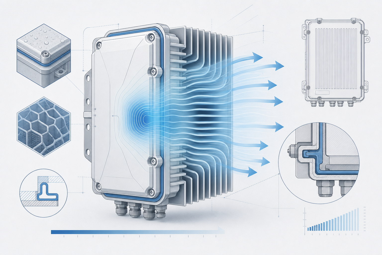
2. Aluminum Die-Cast Enclosure with Integrated Fins
Die-cast aluminum (ADC12 or A380 alloy) is the material of choice for outdoor CPE enclosures. Its thermal conductivity (96â130 W/mK) is 100Ã higher than plastic alternatives. External cooling fins increase surface area by 300â500%, dramatically improving convective heat transfer to ambient air. Modern designs use computational fluid dynamics (CFD) simulation to optimize fin spacing, height, and orientation for maximum natural convection at the target wind speeds for the deployment region.
3. Phase-Change Materials for Peak Load Buffering
For deployments in regions with extreme daily temperature swings, paraffin-based phase-change materials (PCMs) embedded in the enclosure wall can absorb heat during peak afternoon operation and release it during cooler evening hours. This thermal buffering smooths temperature peaks by 8â15°C, extending component lifespan without adding active cooling complexity.
Testing and Validation: Beyond the Datasheet
Real-world thermal validation goes far beyond component datasheet specifications. Reputable CPE manufacturers conduct:
- Thermal chamber cycling: -40°C to +85°C, 500+ cycles, monitoring LTE/5G throughput stability
- Solar load testing: 1,120 W/m² simulated solar radiation at 55°C ambient, 8-hour duration
- Condensation testing: Rapid temperature transitions (85°C to -40°C in 15 seconds) to verify no internal moisture accumulation
- Accelerated life testing: Continuous operation at 85°C component junction temperature for 1,000+ hours
FAQ
Q: Can outdoor CPE use active cooling (fans)?
A: Not in IP67-rated enclosures. Active cooling requires air intake/exhaust, which breaks the dust and water seal. All cooling must be passive. Some industrial designs use sealed liquid cooling loops, but these add cost and complexity rarely justified for CPE.
Q: How does solar radiation affect thermal performance?
A: Direct sunlight adds 500â1,120 W/m² of radiative heat load to the enclosure surface. Light-colored (white or light gray) enclosures with high solar reflectance (>0.85) reduce solar absorption by 40â60% compared to dark-colored units.
Q: What is the typical operating temperature range for outdoor 5G CPE?
A: Industrial-grade designs achieve -40°C to +60°C ambient operation with full RF performance. Extended-temperature variants push to +70°C with graceful performance throttling above 55°C.
Conclusion
Thermal design is the silent differentiator between outdoor 5G CPE that survives a decade in the field and units that fail within the first summer. When evaluating CPE suppliers, buyers should request full thermal validation reports â not just spec sheets â and prioritize manufacturers with in-house environmental testing laboratories and proven field-deployment track records in target climate zones.
Contact Honlly Telecom to discuss outdoor 5G CPE with validated IP67 thermal designs for your deployment region â backed by ISO 9001 manufacturing and full environmental test reports.