Outdoor 5G CPE units face a thermal paradox: the 5G modem and RF front-end generate significant heat during high-throughput operation, yet the IP67-rated enclosure that protects these components from rain, dust, and humidity also traps that heat inside. Solving this thermal management challenge is one of the hardest problems in outdoor CPE engineering — and one that directly determines field reliability and service life.
Why Outdoor CPE Thermal Design Matters
A 5G CPE operating in sub-6 GHz or mmWave bands can dissipate 8\u201315 W during sustained data transfer. In an enclosed plastic or aluminum housing under direct sunlight — where ambient temperatures can reach 55\u00b0C in Middle Eastern or South Asian deployments — internal junction temperatures can exceed 100\u00b0C if cooling is inadequate. At these temperatures, modem performance throttles, RF output power drops, and component lifespan degrades rapidly.
For operators deploying thousands of outdoor CPE units across diverse climate zones, thermal failure is not a theoretical risk — it is a predictable source of support tickets, truck rolls, and customer churn. Engineering the thermal solution correctly at the design stage pays for itself many times over in reduced field failure rates.
IP67 Requirements and the Sealed Enclosure Challenge
IP67 certification requires the enclosure to withstand immersion in 1 meter of water for 30 minutes — meaning the housing must be completely sealed against liquid ingress. This eliminates the simplest cooling method: ventilation. With no airflow through the enclosure, all heat generated by the modem, RF power amplifiers, and power supply must be conducted through the enclosure walls to the external environment.
The engineering challenge breaks into three parts:
- Internal heat spreading: Moving heat from concentrated hot spots (SoC, PA) to the enclosure surface area.
- Enclosure-to-air transfer: Maximizing the rate at which the enclosure surface dissipates heat to ambient air.
- Solar load management: Minimizing solar radiation absorption that adds heat to the system.
Passive Cooling Strategies That Work
Thermal Interface Materials and Heat Spreading
The most critical thermal path in an outdoor CPE is from the modem/SoC die to the enclosure wall. High-performance thermal gap pads or phase-change materials bridge the air gap between the chip package and an aluminum heat spreader plate. The spreader plate — typically 2\u20134 mm thick aluminum — distributes heat across a much larger area than the chip package alone, reducing thermal resistance by an order of magnitude.
In well-designed units, the heat spreader is mechanically bonded to the rear enclosure wall using thermal adhesive or screw-mounted with thermal grease. This creates a direct conduction path from silicon to the outside world, bypassing the insulating air gap inside the enclosure.
Enclosure Material Selection
Aluminum alloy enclosures (typically ADC12 or AL6061) offer approximately 100\u2013200x the thermal conductivity of plastic (PC/ABS). For outdoor CPE targeting ambient temperatures above 45\u00b0C, an aluminum housing is often the difference between sustained gigabit throughput and thermal throttling within 30 minutes.
Where plastic enclosures are preferred for cost or RF transparency reasons, manufacturers may embed aluminum inserts or use thermally conductive plastics with filler materials (graphite, ceramic, or boron nitride). These materials achieve 5\u201310 W/m\u00b7K — better than standard plastics (0.2 W/m\u00b7K) but still far below aluminum (150\u2013200 W/m\u00b7K).
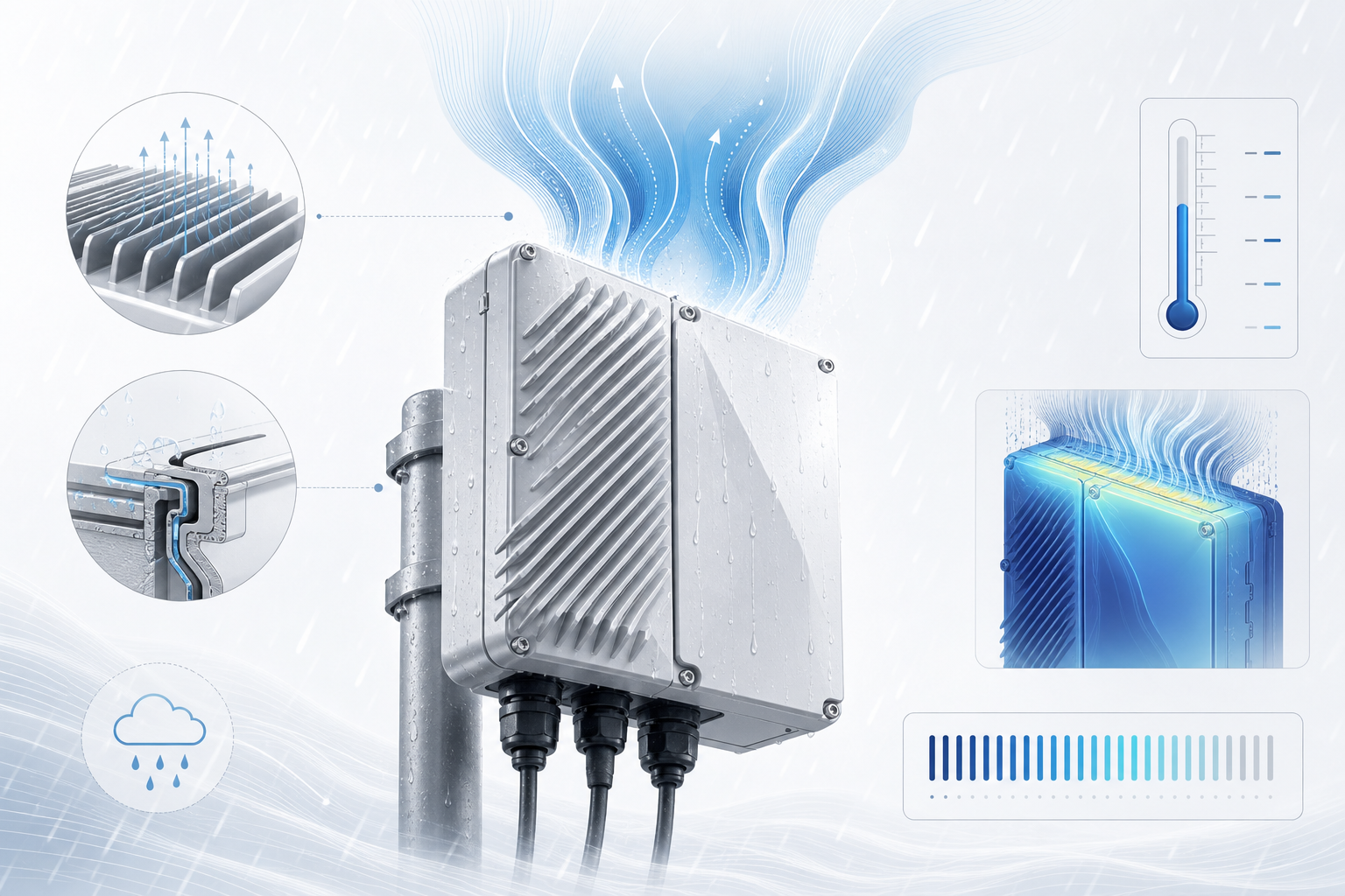
External Fin Design
Adding fins to the exterior enclosure surface increases the surface area available for convective and radiative heat transfer. A finned aluminum enclosure can improve heat dissipation by 40\u201360% compared to a smooth surface of the same footprint, without compromising the IP67 seal — since the fins are part of the solid enclosure casting, not openings.
Fin orientation matters in outdoor installations: vertical fins promote natural convection (hot air rises along the fin channels), while horizontal fins trap heat. The best outdoor CPE designs orient fins vertically regardless of mounting position.
Solar Radiation: The Overlooked Heat Load
An outdoor CPE installed on a rooftop or exterior wall in direct sunlight can absorb 600\u20131000 W/m\u00b2 of solar radiation. A unit with a 0.05 m\u00b2 surface area facing the sun adds 30\u201350 W of external heat load — several times the internal heat generation from the electronics.
Mitigation strategies include:
- High-reflectivity surface coating: White or light-colored enclosures with a solar reflectance index (SRI) above 80 reflect most solar energy. A white aluminum enclosure can operate 10\u201315\u00b0C cooler than a dark grey equivalent.
- Sun shield design: A secondary shield mounted with an air gap above the main enclosure blocks direct radiation while allowing airflow in the gap.
- Installation guidelines: Specifying north-facing mounting (in the northern hemisphere) or shaded locations in deployment documentation reduces solar exposure without hardware changes.
Testing and Validation for Extreme Environments
Responsible CPE vendors validate thermal performance through environmental stress testing:
- Thermal chamber testing: Operating the CPE at 55\u00b0C ambient with maximum throughput load for 24+ hours, monitoring modem temperature and throughput stability.
- Solar simulation: Exposing the CPE to calibrated solar spectrum lamps at 1000 W/m\u00b2 while measuring internal temperatures.
- Thermal shock cycling: Rapid transitions between -20\u00b0C and +60\u00b0C to verify that thermal expansion/contraction does not compromise the IP67 seal or damage solder joints.
- Field pilot testing: Deploying units in target climate zones (e.g., Gulf region summer, Nordic winter) for 3\u20136 month validation before volume shipment.
Operators evaluating outdoor CPE should request thermal validation reports — not just IP rating certificates — as part of vendor qualification. A unit that passes IP67 in a lab at 25\u00b0C may fail in the field at 55\u00b0C if thermal management was an afterthought.
FAQ
Does passive cooling limit 5G throughput?
A properly designed passive cooling system does not limit throughput under normal operating conditions. The thermal solution should be sized for worst-case ambient temperature and continuous maximum load. If thermal throttling occurs during sustained throughput, the cooling design is undersized for the deployment environment.
Why not use active cooling with a fan?
Fans create an opening in the enclosure, which breaks the IP67 seal. While fan-protected enclosures with IP55 ratings exist, they add a mechanical failure point (fan bearing), increase power consumption, and require filter maintenance. For carrier-grade outdoor CPE, passive cooling is strongly preferred for reliability.
How do you verify thermal performance before buying?
Ask the vendor for: (a) thermal simulation reports showing junction temperatures at maximum rated ambient, (b) environmental chamber test logs with throughput data, and (c) field trial results from deployments in climate zones similar to your own. A vendor that cannot provide these documents has not validated their thermal design.
Deploying outdoor 5G CPE in challenging environments? Contact Honlly Telecom to discuss thermal performance data and explore our IP67-rated outdoor CPE portfolio engineered for extreme conditions.