Category: Blog

Technical guides and best practices

  • A Technical Buyer’s Guide to 5G CPE MIMO Antenna Design: Configurations, Beamforming, and Field Performance

    A Technical Buyer’s Guide to 5G CPE MIMO Antenna Design: Configurations, Beamforming, and Field Performance

    Antenna performance is the single most underestimated variable in 5G CPE procurement. While modem chipsets, firmware stacks, and WAN interfaces dominate specification sheets, the antenna subsystem — its topology, gain, polarization, and beam-steering capability — determines whether a CPE delivers 50 Mbps or 500 Mbps in the same location. For B2B buyers sourcing devices at scale, understanding antenna design is not optional: it is the difference between a successful deployment and a fleet-wide performance gap.

    MIMO Configurations: 2×2, 4×4, and Beyond

    The MIMO (Multiple-Input Multiple-Output) configuration defines how many independent transmit and receive paths a CPE supports. A 2×2 MIMO CPE uses two antenna elements at each end of the link; a 4×4 MIMO system uses four. The relationship between MIMO layers and throughput is near-linear in good signal conditions — a 4×4 CPE can approximately double the downlink throughput of a 2×2 device on the same cell.

    However, the practical benefit depends on the network side. If the gNB (5G base station) is only configured for 2-layer transmission — common in early mid-band deployments — the extra receive paths on a 4×4 CPE still provide diversity gain and improved SINR, but throughput multiplication is limited. B2B buyers should match CPE MIMO order to the operator’s deployed antenna configuration at target sites. For most enterprise deployments accessing 3.5 GHz n78 or C-band n77 networks, 4×4 MIMO is now the baseline recommendation, with 2×2 reserved for cost-sensitive indoor applications where signal conditions are already strong.

    Antenna Gain: More Is Not Always Better

    Antenna gain, measured in dBi, represents the antenna’s ability to concentrate radiated energy in a particular direction. A high-gain antenna (8–12 dBi) focuses energy into a narrow beam, improving range and signal strength but reducing coverage angular width. Low-gain antennas (2–5 dBi) provide omnidirectional coverage at the expense of range.

    For outdoor fixed wireless CPE deployed in suburban or rural settings with a known cell site direction, directional high-gain antennas deliver maximum link budget. For urban indoor CPE where multipath reflections dominate and cell sites may be in multiple directions, moderate-gain omnidirectional or switched-beam antennas often outperform high-gain directional solutions. The procurement decision should be informed by a site survey — or at minimum, by operator-provided coverage maps indicating cell site azimuths relative to deployment locations.

    Beamforming and Beam Steering Technologies

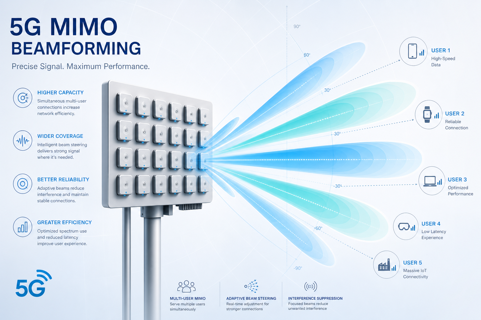
    5G NR introduces sophisticated beam management that distinguishes it from LTE. Beamforming — the ability to shape and steer transmission beams electronically — operates at both the gNB and CPE sides. On the CPE, beamforming is implemented through phased antenna arrays that adjust phase relationships across elements to create constructive interference in the desired direction.

    Several CPE beamforming approaches exist in current commercial devices:

    Switched-Beam Systems. A fixed set of pre-defined beam patterns (typically 4–8) is stored in firmware. The CPE selects the beam pattern yielding the highest RSRP (Reference Signal Received Power). Switched-beam is cost-effective and deterministic but cannot adapt to continuously changing multipath conditions.

    Adaptive Beamforming. The CPE continuously adjusts phase and amplitude weights across antenna elements, steering the beam in real time based on SINR feedback. This approach handles mobility and environmental changes — a delivery truck temporarily blocking the line of sight, for instance — but requires more complex RF front-end and baseband processing.

    Hybrid Beamforming. Combining analog beamforming in the RF domain with digital precoding in baseband, hybrid architectures balance performance and complexity. Most premium 5G CPEs shipping in 2026 use hybrid beamforming, particularly for mmWave (FR2) bands where narrow beams are essential.

    Polarization and Cross-Polarization Discrimination

    5G NR supports dual-polarized transmission, where orthogonal polarizations (typically ±45° slant) carry independent data streams — effectively doubling capacity without additional spectrum. This is standard in 4×4 MIMO configurations, where two polarizations × two physical antenna elements create four effective channels.

    Cross-Polarization Discrimination (XPD) measures how well the CPE antenna maintains polarization separation. Poor XPD causes inter-stream interference, eroding MIMO gains. When evaluating CPE antenna specifications, look for XPD values above 15 dB in the main beam direction. This is particularly critical for outdoor CPE in rainy environments, where depolarization from water droplets on radome surfaces degrades XPD in poorly designed enclosures.

    Internal vs. External Antennas: Deployment Trade-offs

    Internal antennas — integrated within the CPE enclosure — simplify installation and improve industrial design. Modern internal antenna designs using laser-direct structuring (LDS) on molded plastic carriers can achieve gain figures within 1–2 dB of external alternatives in mid-band frequencies. The trade-off is enclosure volume and thermals: antennas need physical separation (typically λ/2, approximately 43 mm at 3.5 GHz), constraining minimum device dimensions.

    External antennas, connected via SMA or TS-9 connectors, offer deployment flexibility. A CPE installed inside a metal-clad building or equipment enclosure may need external antennas mounted outside. External antennas also enable antenna diversity — placing two antennas several wavelengths apart to combat spatial fading. For industrial deployments in challenging RF environments, CPEs with external antenna ports remain the preferred choice, even if internal antennas suffice for benign locations.

    Antenna-to-Modem Integration and RF Front-End Losses

    A specification sheet listing a 5 dBi antenna gain is meaningless if the RF path from antenna to modem introduces 3 dB of insertion loss through connectors, PCB traces, and filters. B2B buyers should request OTA (Over-The-Air) TRP (Total Radiated Power) and TIS (Total Isotropic Sensitivity) measurements — not just antenna datasheet gain — as these capture the end-to-end system performance including all front-end losses. A well-integrated 3 dBi antenna system with low insertion loss can outperform a 6 dBi antenna with 4 dB of path loss.

    Field Validation: What to Measure

    When evaluating CPE antenna performance in the field, four metrics matter most:

    • RSRP (Reference Signal Received Power): Measures the received power of 5G reference signals; above -100 dBm is good, below -115 dBm indicates marginal coverage.
    • SINR (Signal-to-Interference-plus-Noise Ratio): A quality metric; values above 20 dB enable 256QAM modulation and maximum throughput. Values below 10 dB limit modulation to QPSK.
    • Rank Indicator (RI): Reports how many independent MIMO layers the CPE can resolve. An RI of 4 confirms full 4-layer MIMO operation.
    • Throughput stability: Measure throughput variance over hours, not seconds. A CPE that delivers 400 Mbps in a burst test but fluctuates between 100–400 Mbps in sustained operation has an antenna or thermal problem.

    Antenna design is not a commodity feature — it is the differentiating factor that separates a CPE that meets its specification from one that delivers it in the real world. For B2B buyers making procurement decisions at scale, antenna performance evaluation should command as much attention as the modem chipset and software stack combined. In 5G, the best baseband cannot compensate for a compromised RF path.

    Related Resources from Honlly Telecom:
  • A Technical Buyer’s Guide to Wi-Fi 7 and 5G CPE Convergence: Multi-Link Operation, 320 MHz Channels, and Enterprise Deployment Architecture for Next-Generation Wireless Access

    A Technical Buyer’s Guide to Wi-Fi 7 and 5G CPE Convergence: Multi-Link Operation, 320 MHz Channels, and Enterprise Deployment Architecture for Next-Generation Wireless Access

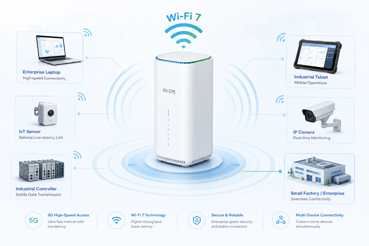
    As enterprise wireless networks brace for the next capacity leap, the convergence of 5G CPE and Wi-Fi 7 (IEEE 802.11be) represents one of the most consequential architectural shifts in access network design since the transition from Wi-Fi 5 to Wi-Fi 6. For telecom operators, ISPs, and enterprise IT buyers evaluating CPE procurement in 2026, understanding how Wi-Fi 7 capabilities integrate with 5G WAN connectivity—and what this means for real-world throughput, latency, and spectrum management—is no longer optional. It is a procurement imperative.

    Why Wi-Fi 7 Matters for 5G CPE

    Wi-Fi 7 is not an incremental upgrade. The standard delivers maximum theoretical throughput of 46 Gbps—roughly 4.8× that of Wi-Fi 6—through three foundational innovations: 320 MHz channel bandwidth (doubled from Wi-Fi 6’s 160 MHz), 4096-QAM modulation (up from 1024-QAM), and Multi-Link Operation (MLO), which enables simultaneous transmission across multiple frequency bands. When these capabilities are embedded in a 5G CPE that terminates a multi-gigabit 5G WAN link, the result is a gateway device that can serve 50+ concurrent enterprise clients without becoming a bottleneck.

    Consider the enterprise branch office scenario: a 5G CPE receiving 2 Gbps downlink over n78 with 100 MHz of spectrum. A Wi-Fi 6 access layer behind this CPE would realistically deliver 600–800 Mbps per client under ideal conditions. Wi-Fi 7, with MLO aggregating 5 GHz and 6 GHz bands simultaneously, can push 1.5–2 Gbps to individual capable clients—matching the WAN capacity rather than throttling it. For latency-sensitive applications like cloud-based UCaaS, virtual desktop infrastructure, and real-time industrial control, Wi-Fi 7’s deterministic low-latency features (including restricted target wake time) reduce tail latency by up to 60% compared to Wi-Fi 6 in congested environments.

    Multi-Link Operation: The Architecture Game-Changer

    MLO is Wi-Fi 7’s defining innovation and the feature with the most profound implications for 5G CPE design. In conventional Wi-Fi architectures, a client associates with a single band at a time—2.4 GHz, 5 GHz, or 6 GHz. MLO allows a Wi-Fi 7 client and access point to maintain simultaneous links across two or three bands, dynamically steering traffic based on channel conditions, interference, and QoS requirements.

    For a 5G CPE functioning as the Wi-Fi 7 AP, MLO enables several deployment-critical capabilities. First, it provides seamless band steering without the connection interruption inherent in traditional band-steering mechanisms. A client moving from a 6 GHz-dominated office zone to a 5 GHz-dominated common area maintains uninterrupted connectivity. Second, MLO’s link aggregation mode—where traffic is striped across multiple bands—effectively doubles or triples the per-client throughput ceiling. Third, MLO’s redundancy mode allows critical traffic to be duplicated across bands, achieving sub-millisecond failover for industrial and telemedicine applications.

    Enterprises evaluating 5G CPE with Wi-Fi 7 should verify that the device supports at least STR (Simultaneous Transmit and Receive) MLO across 5 GHz + 6 GHz, not just the less capable eMLSR (enhanced Multi-Link Single Radio) mode that some early chipsets implement. STR MLO requires dual-radio RF front-end design and adds approximately USD 12–18 to the bill of materials—an investment that pays for itself in environments with more than 30 active clients.

    320 MHz Channels and 6 GHz Spectrum Planning

    Wi-Fi 7’s 320 MHz channel support is transformative for high-throughput enterprise applications, but it demands careful spectrum planning—particularly in the 6 GHz band (5.925–7.125 GHz), where regulatory availability varies significantly by country. As of mid-2026, approximately 62 countries have opened portions of the 6 GHz band for unlicensed use, but the specific sub-band allocations differ: the U.S. has made the full 1,200 MHz available, the EU has released the lower 500 MHz (5.945–6.425 GHz), and many Asia-Pacific countries have adopted a middle-ground approach.

    A globally deployable 5G CPE with Wi-Fi 7 must support software-configurable 6 GHz channelization that adapts to local regulatory domains without hardware changes. This capability—sometimes called geo-aware channel provisioning—should be a baseline requirement in operator RFPs. Enterprises should also confirm that the CPE supports Automated Frequency Coordination (AFC) where required, particularly for standard-power 6 GHz operation in the U.S. and Canada, to avoid interference with incumbent fixed-service and fixed-satellite users.

    Integration Architecture: Where 5G Meets Wi-Fi 7

    The integration of a 5G NR modem and a Wi-Fi 7 access point within a single CPE enclosure introduces engineering challenges that extend beyond RF coexistence. Thermal management is the primary concern: a Cat 19 or Cat 20 5G modem transmitting at +23 dBm alongside a tri-band Wi-Fi 7 chipset can generate 12–15W of sustained thermal load. Passive cooling designs using advanced thermal interface materials and chassis-as-heatsink approaches are essential for fanless operation in enterprise environments where acoustic noise and dust ingress are unacceptable.

    On the software side, the CPE’s embedded operating system must implement intelligent traffic steering between the 5G WAN and Wi-Fi 7 LAN domains. This includes DSCP-to-802.11be QoS mapping that preserves DiffServ markings across the gateway, buffer management that prevents Wi-Fi 7’s higher throughput from overwhelming the 5G link’s buffer (bufferbloat mitigation), and per-client airtime fairness algorithms that prevent a single Wi-Fi 7 client from monopolizing shared airtime. OpenWrt-based CPE platforms with configurable sqm (Smart Queue Management) and the CAKE qdisc are increasingly preferred by enterprise buyers who require transparent traffic management without proprietary lock-in.

    Procurement Checklist for Wi-Fi 7 + 5G CPE

    When evaluating Wi-Fi 7-integrated 5G CPE for enterprise deployment, operators and buyers should assess against the following technical criteria:

    Radio Capabilities: Tri-band concurrent operation (2.4 + 5 + 6 GHz), STR MLO support (not eMLSR-only), 4×4 MU-MIMO on 5 GHz and 6 GHz, 4096-QAM on all bands, and configurable 320/160/80 MHz channel bandwidth.

    5G WAN Integration: 3GPP Release 17 or later modem, 4×4 MIMO on sub-6 GHz with carrier aggregation (at least 3CC), support for n77/n78/n79 plus at least four additional FR1 bands for global deployment flexibility, and an external antenna port option for edge-of-cell installations.

    Software and Management: TR-069/TR-369 (USP) support for operator ACS integration, zero-touch provisioning with secure bootstrap, VLAN-to-SSID mapping for multi-tenant deployments, WPA3-Enterprise with 802.1X and RADIUS integration, and geo-aware 6 GHz channel provisioning.

    Hardware Architecture: Fanless passive cooling rated to 45°C ambient, 2.5 GbE LAN port (minimum one, preferably two with link aggregation), USB-C for optional external storage or debug console, and industrial temperature range (-20°C to +55°C) for outdoor or unconditioned-space installations.

    The era of treating Wi-Fi as a downstream afterthought in CPE design is over. As 5G networks deliver multi-gigabit WAN capacity to the enterprise edge, the access layer must keep pace. Wi-Fi 7 is the technology that closes that gap—and the CPE that integrates it well will define the enterprise connectivity experience for the next five years.

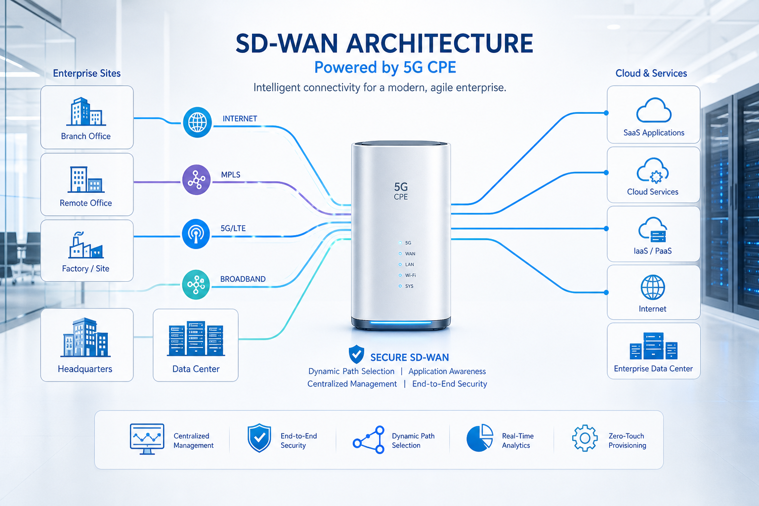
  • A Technical Buyer’s Guide to Multi-WAN SD-WAN Integrated 5G CPE: Link Aggregation, Intelligent Failover Architecture, and Enterprise Branch Deployment Planning

    A Technical Buyer’s Guide to Multi-WAN SD-WAN Integrated 5G CPE: Link Aggregation, Intelligent Failover Architecture, and Enterprise Branch Deployment Planning

    As enterprise branch networks evolve beyond the traditional MPLS-and-backup-4G model, multi-WAN SD-WAN integrated 5G CPE is emerging as the primary connectivity platform for distributed organizations in 2026. This technical buyer’s guide examines the architecture, key evaluation criteria, and deployment planning considerations for operators and enterprises procuring next-generation multi-WAN CPE.

    The Architectural Shift: From Backup to Active-Active Multi-Path

    The legacy model treated cellular WAN as a cold standby — a 4G LTE dongle that activated only when the primary MPLS or broadband circuit failed. Modern multi-WAN 5G CPE fundamentally changes this paradigm. With 5G delivering fiber-class throughput (500 Mbps to 2+ Gbps) and sub-20ms latency, the cellular path is now a viable primary or active-active link alongside wired WAN connections.

    This architectural shift demands CPE with:

    • Hardware-Accelerated SD-WAN Forwarding: Multi-gigabit IPsec throughput with AES-256-GCM encryption offloaded to dedicated silicon. Software-only forwarding on a general-purpose CPU will bottleneck at sub-500 Mbps under real-world traffic conditions with small packets and concurrent tunnel termination.
    • Application-Aware Path Selection: Dynamic per-packet or per-flow steering based on application signatures (DPI), real-time link quality metrics (jitter, loss, latency), and administrator-defined policies. A VoIP call may be steered over the lowest-jitter path while bulk file transfers use the highest-bandwidth link.
    • Sub-Second Failover with Session Persistence: True hitless failover requires BFD (Bidirectional Forwarding Detection) at sub-100ms intervals combined with connection tracking that preserves established TCP sessions and VPN tunnels across path transitions. Anything slower than 500ms total failover time will disrupt real-time applications and trigger application-layer timeouts.

    WAN Interface Portfolio: What to Look For

    A production-grade multi-WAN CPE should support a flexible combination of WAN interfaces:

    | Interface Type | Typical Use Case | Key Specification |

    |—|—|—|

    | 5G NR (SA/NSA) | Primary or active-active cellular path | 3GPP Release 17, 4×4 MIMO, carrier aggregation up to 8CC |

    | 4G LTE Cat 20 | Fallback cellular path | Multi-operator SIM support, eSIM ready |

    | 2.5GbE / 10GbE WAN | Fiber/FTTx handoff | SFP+ cage for optical modules |

    | 1GbE / 2.5GbE LAN | Local switching, PoE for APs/cameras | 802.3at PoE+ (30W per port) |

    | Wi-Fi 7 (802.11be) | On-site wireless access, wireless WAN backup | 4×4 MIMO, MLO, 320 MHz channels |

    The CPE should expose each WAN interface independently to the SD-WAN policy engine, with per-interface health probes (ICMP, HTTP, DNS) and configurable SLA thresholds that trigger automated path reassignment.

    SD-WAN Overlay Technologies: Standards-Based vs. Proprietary

    Buyers face a critical architectural choice between standards-based overlay protocols and vendor-proprietary SD-WAN fabrics:

    • Standards-Based (IPsec/IKEv2 + VXLAN/Geneve): Maximizes interoperability with existing enterprise infrastructure and multi-vendor environments. However, it may lack advanced features like forward error correction (FEC) and per-packet duplication that proprietary protocols offer.
    • Vendor-Proprietary SD-WAN (Cisco vEdge, VMware VeloCloud, Fortinet Secure SD-WAN): Delivers tightly integrated security, FEC, and cloud on-ramp optimizations, but can create vendor lock-in and complicate multi-vendor CPE strategies.

    The emerging best practice among large enterprises is to select CPE hardware that supports both paradigms — running standards-based tunnels for general connectivity while integrating with a proprietary SD-WAN fabric for latency-sensitive and high-security workloads.

    Security Architecture: Zero Trust at the Branch Edge

    Multi-WAN CPE sits at the boundary between the enterprise LAN and multiple untrusted WAN paths, making it a critical security enforcement point. Key security capabilities to evaluate:

    • NGFW Integration: Layer 7 application identification, intrusion prevention (IPS), and TLS 1.3 decryption at line rate. The CPE should not become a security bottleneck when performing deep packet inspection on multi-gigabit 5G links.
    • Zero Trust Network Access (ZTNA): The CPE should act as a ZTNA enforcement point, authenticating every flow against the enterprise identity provider before granting access to internal applications — regardless of which WAN path the traffic arrives on.
    • SASE / SSE Integration: Native integration with cloud-delivered security services (SWG, CASB, DLP) via GRE/IPsec tunnels or API-driven service chaining, enabling consistent security policy across all branch locations without backhauling traffic through a central data center.

    Centralized Management and Zero-Touch Provisioning

    For deployments spanning hundreds or thousands of branch locations, the CPE management plane is as important as the data plane:

    • Zero-Touch Provisioning (ZTP): The CPE should bootstrap from a factory-default state upon first power-on — authenticating to the orchestrator via TPM-stored device certificates, downloading configuration, and establishing SD-WAN tunnels without any on-site technician intervention.
    • Template-Based Configuration Management: Hierarchical configuration models that allow global policy definition with local overrides for region-specific parameters (cellular bands, regulatory domain, SSID naming).
    • Telemetry and Analytics: Streaming telemetry (gNMI, NETCONF/YANG) that feeds into the enterprise observability stack, providing per-application, per-path performance metrics for capacity planning and SLA monitoring.

    Deployment Planning Checklist

    For operators and enterprises planning a multi-WAN SD-WAN CPE rollout:

    Site Survey: Verify 5G coverage (signal strength, RSRP, SINR) at each branch location, not just at street level but at the precise CPE installation point — indoor attenuation at higher 5G frequencies (n77/n78) can be significant.

    SIM Strategy: Multi-IMSI or eSIM profiles that allow failover between mobile operators without physical SIM swaps. Evaluate roaming agreements for cross-border branch deployments.

    IP Addressing and Routing: Plan for the SD-WAN overlay’s impact on existing IP addressing schemes. Dynamic routing protocol redistribution (BGP, OSPF) from CPE to LAN core switches.

    Power and Environmental: For branch locations without dedicated IT rooms, the CPE must tolerate ambient temperatures up to 50°C, operate fanless for dust-sensitive environments, and support PoE-powered operation for flexible placement.

    Lifecycle and Support: Evaluate vendor commitments to firmware update cadence (monthly security patches, quarterly feature releases), hardware warranty (minimum 3-year with advanced replacement), and 24/7 TAC support coverage across all deployment time zones.

    The Bottom Line

    Multi-WAN SD-WAN integrated 5G CPE is not a commodity product — it is a strategic infrastructure decision that shapes branch network architecture for a 5-7 year lifecycle. Buyers should prioritize hardware-accelerated forwarding, standards-based overlay flexibility, integrated zero-trust security, and centralized ZTP management as table-stakes requirements. The CPE that delivers all four will provide the foundation for enterprise branch connectivity well into the 6G era.

  • A Technical Buyer’s Guide to QoS and Network Slicing in 5G CPE: End-to-End Slice-Aware Architecture, 5QI Mapping, and Multi-Service Deployment Planning for Operators

    A Technical Buyer’s Guide to QoS and Network Slicing in 5G CPE: End-to-End Slice-Aware Architecture, 5QI Mapping, and Multi-Service Deployment Planning for Operators

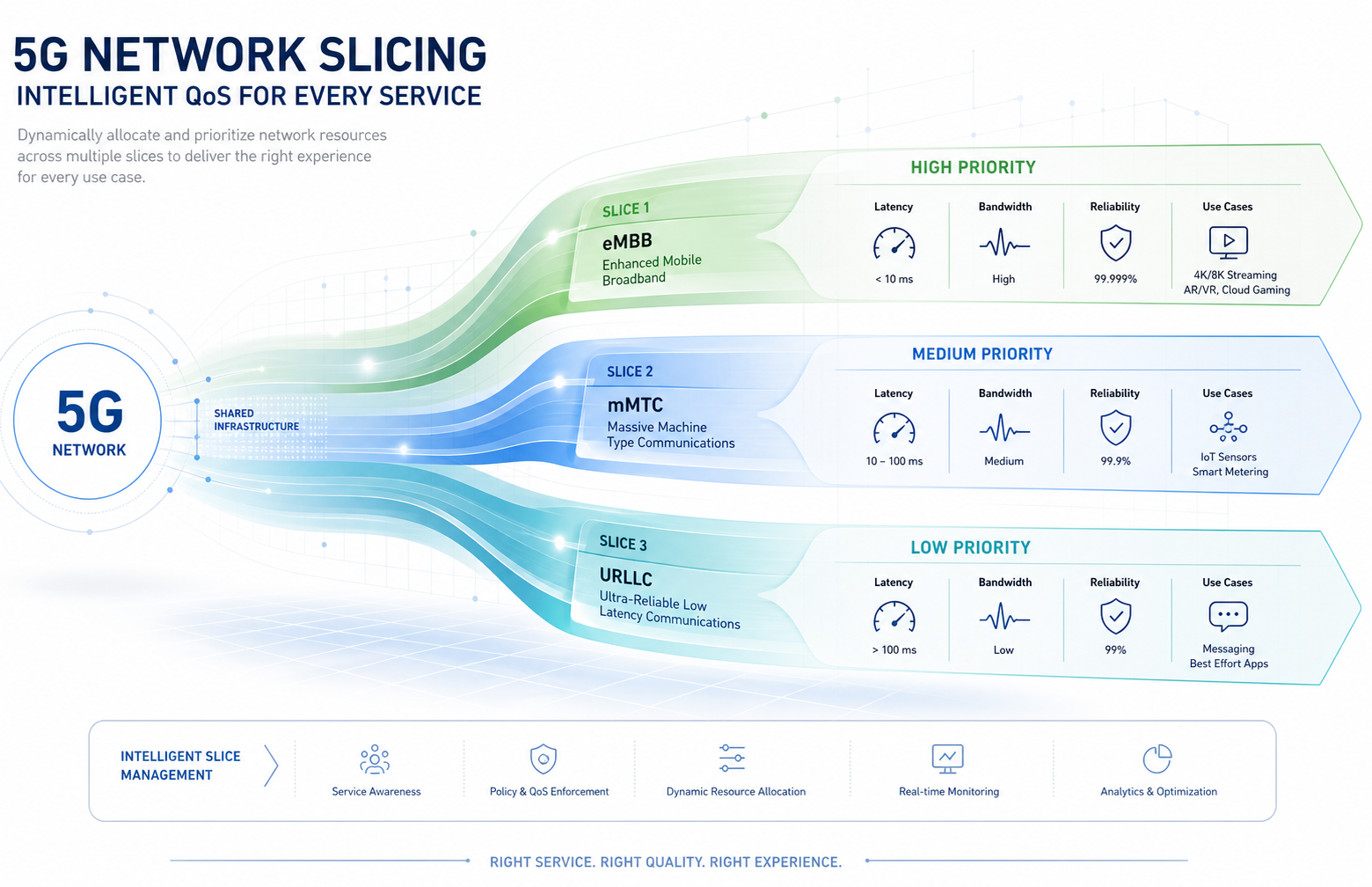
    Network slicing is one of the defining architectural features of 5G Standalone (SA), enabling operators to deliver multiple virtualized networks over a shared physical infrastructure — each with its own performance characteristics, security policies, and service guarantees. For CPE buyers, understanding how network slicing is implemented at the subscriber endpoint is essential to making informed procurement decisions. This guide examines the QoS framework, slice identification, and CPE-level architecture that operators need to evaluate when selecting 5G CPE for multi-service deployments.

    The 5G QoS Model: Beyond 4G Bearer Architecture

    5G introduces a fundamentally more flexible QoS framework than 4G LTE. The 5G QoS Identifier (5QI) replaces the QCI model with finer granularity and standardized packet delay budgets across 33 defined 5QI values (versus 9 QCIs in LTE). Key 5QI characteristics that CPE must handle include:

    • GBR (Guaranteed Bit Rate) QoS Flows for services requiring committed throughput, such as enterprise VPN tunnels, real-time video conferencing, and industrial control traffic
    • Non-GBR QoS Flows with standardized priority levels, suitable for general internet access and best-effort enterprise traffic
    • Delay-Critical GBR (5QI 82-85) for ultra-reliable low-latency applications requiring sub-5ms packet delay budgets
    • Reflective QoS — where the CPE derives uplink QoS rules from downlink packet markings, reducing signaling overhead for dynamic traffic patterns

    A properly designed 5G CPE must maintain independent QoS flow state for multiple concurrent PDU sessions, each potentially carrying multiple QoS flows with different 5QI profiles. This is a non-trivial requirement that separates enterprise-grade CPE from consumer-grade devices.

    Network Slice Identification: NSSAI and S-NSSAI

    Network slicing in 5G is identified through the Single Network Slice Selection Assistance Information (S-NSSAI), composed of a Slice/Service Type (SST) and an optional Slice Differentiator (SD). Standardized SST values include eMBB (SST=1), URLLC (SST=2), and MIoT (SST=3), with operator-defined values available for custom slice types.

    The CPE receives a Configured NSSAI from the core network during registration, which defines the slices the device is authorized to access. Critically, the CPE must then be capable of establishing separate PDU sessions on different slices simultaneously — a capability known as multi-slice support. For enterprise CPE deployments, this means one device might concurrently maintain:

    • A URLLC slice PDU session for factory automation traffic (SST=2, latency <5ms)
    • An eMBB slice PDU session for office internet access (SST=1, high throughput)
    • A custom MIoT slice for sensor aggregation (SST=3, low power, massive connectivity)

    URSP: The Traffic-to-Slice Routing Engine

    The UE Route Selection Policy (URSP) is the mechanism by which the 5G core instructs the CPE on how to route application traffic to specific network slices. URSP rules consist of traffic descriptors (IP tuples, FQDN, DNN, application IDs) mapped to route selection descriptors (S-NSSAI, DNN, SSC mode).

    For enterprise buyers, URSP support in CPE translates to a practical capability: the ability to enforce slice-based traffic steering without per-application configuration on end-user devices behind the CPE. A well-implemented CPE can, for example, automatically route all traffic destined for a manufacturing execution system to the URLLC slice while directing office productivity traffic to the eMBB slice — transparently to the LAN devices.

    Multi-Slice CPE Architecture: VLAN-to-Slice Mapping

    Enterprise-grade 5G CPE typically implements slice-to-VLAN mapping as the bridge between the 5G WAN and the local area network. Each PDU session (one per slice) is mapped to a distinct VLAN on the CPE’s LAN ports, allowing downstream switches and routers to segregate traffic by slice without 5G awareness.

    A reference multi-slice CPE architecture includes:

    • Multi-PDU Session Engine — supporting 4-8 concurrent PDU sessions with independent IP stacks per session
    • URSP Client — processing URSP rules from the 5G core and maintaining a local traffic-to-slice routing table
    • VLAN Translation Layer — mapping each PDU session to a configurable 802.1Q VLAN tag on the LAN side
    • Per-Slice QoS Enforcement — maintaining independent QoS flow state per PDU session with hardware-accelerated packet scheduling

    Performance and Isolation Guarantees

    A critical procurement consideration is the degree of resource isolation between slices at the CPE level. While the 5G core guarantees slice isolation within the network, the CPE itself must not become a bottleneck through shared buffer contention, CPU oversubscription, or inadequate packet scheduling. Buyers should verify:

    • Per-slice throughput floors that are maintained regardless of traffic load on other slices
    • Hardware queue separation — dedicated hardware queues per slice rather than software-based prioritization
    • Slice-specific latency budgets measured end-to-end from LAN ingress to 5G air interface
    • Fail-open behavior — documented behavior when a slice becomes unavailable (traffic fallback policies)

    Buyer’s Verification Checklist

    When evaluating 5G CPE for multi-slice deployment, procurement teams should request:

    1. Documented multi-PDU session support with a minimum of 4 concurrent sessions
    2. URSP rule capacity (minimum 8 traffic descriptor + route selection descriptor pairs)
    3. VLAN-to-slice mapping configuration interface (GUI and TR-069/TR-369 manageable)
    4. Per-slice throughput and latency test reports under simultaneous multi-slice load
    5. Interoperability test results with the operator’s specific 5G SA core vendor (Ericsson, Nokia, Huawei, Samsung, Mavenir)
    6. Software upgrade path for 3GPP Release 17/18 slice enhancements including slice-level authentication and authorization (NSSAA)

    Conclusion: Slice-Aware CPE as a Competitive Requirement

    As 5G SA networks mature through 2026, network slicing is transitioning from a standards capability to a commercial service differentiator. Operators launching enterprise slicing services need CPE that translates core-network slice intelligence into practical LAN-side traffic management. CPE without robust multi-slice support, URSP processing, and per-slice QoS enforcement will increasingly limit an operator’s ability to monetize their 5G SA investment. For procurement teams, slice-aware CPE is not a future consideration — it is a present requirement for any 5G SA deployment targeting enterprise, industrial, or multi-service consumer markets.

  • A Technical Buyer’s Guide to eSIM and Multi-IMSI Architecture in 5G CPE: eUICC Integration, GSMA Compliance, and Remote SIM Provisioning for Global Operator Deployments

    A Technical Buyer’s Guide to eSIM and Multi-IMSI Architecture in 5G CPE: eUICC Integration, GSMA Compliance, and Remote SIM Provisioning for Global Operator Deployments

    As 5G fixed wireless access deployments scale globally, a seemingly simple component — the SIM — is undergoing a transformation that has far-reaching implications for CPE procurement, logistics, and operational efficiency. The embedded SIM (eSIM) and its multi-IMSI architecture, governed by GSMA’s SGP.22 and SGP.32 specifications, enable operators to provision, swap, and manage operator profiles on CPE devices without physical SIM card handling. For ISPs, MVNOs, and enterprise operators managing fleets of thousands of distributed CPE units, eSIM technology is not a convenience feature — it is a strategic procurement requirement that directly impacts total cost of ownership, supply chain agility, and subscriber churn.

    This technical buyer’s guide examines the eSIM and multi-IMSI architecture as it applies to 5G CPE, covering the GSMA compliance framework, hardware integration considerations, remote SIM provisioning workflows, and practical vendor evaluation criteria for procurement teams specifying next-generation FWA devices.

    eSIM Architecture Fundamentals: eUICC, Profiles, and the LPA

    At the hardware level, an eSIM implementation in a 5G CPE device consists of an embedded UICC (eUICC) — a soldered, tamper-resistant secure element that conforms to the GSMA SGP.02 (M2M) or SGP.22 (consumer) architecture. Unlike a traditional removable SIM card, the eUICC supports multiple operator profiles stored simultaneously, with secure over-the-air (OTA) profile download, activation, and deletion managed through a Local Profile Assistant (LPA) component integrated into the CPE’s baseband or application processor.

    The key architectural choice for CPE procurement teams is between the M2M eUICC architecture (GSMA SGP.02) and the consumer eUICC architecture (GSMA SGP.22):

    M2M eUICC (SGP.02). Designed for device-to-device and IoT use cases, the M2M architecture uses a “push” model where the operator’s Subscription Manager-Data Preparation (SM-DP) server pushes profiles to the eUICC through a Subscription Manager-Secure Routing (SM-SR) intermediary. This architecture is well-suited to fixed-location CPE with predictable network attachment patterns, but it requires operator-side SM-SR infrastructure that not all MVNOs maintain.

    Consumer eUICC (SGP.22). The consumer architecture uses a “pull” model where the CPE’s LPA initiates profile download from the SM-DP+ server — the operator-controlled platform that prepares and delivers encrypted profiles. SGP.22 is the dominant architecture for smartphones and is increasingly adopted in FWA CPE because it enables end-user or installer-initiated profile switching, supports QR-code-based activation workflows, and integrates naturally with operator mobile apps and self-service portals.

    For most FWA and enterprise CPE deployments, SGP.22 consumer eUICC is the recommended architecture due to broader ecosystem support, simpler operator onboarding, and alignment with GSMA SGP.32 — the emerging IoT eSIM standard that extends consumer architecture capabilities to constrained devices.

    Multi-IMSI Architecture: Enabling Operator Flexibility at the CPE Level

    While eSIM enables profile portability, multi-IMSI capability enables profile concurrency. A multi-IMSI CPE device stores multiple International Mobile Subscriber Identities — each associated with a distinct operator profile — and can switch between them based on network availability, cost optimization rules, or geographic location without requiring a profile download.

    In a 5G CPE context, multi-IMSI architecture serves three primary deployment scenarios:

    Multi-Carrier Failover for SLA-Grade Deployments. Enterprise CPE deployed at branch offices, retail locations, or remote industrial sites can maintain active IMSIs from two or more operators. If the primary operator’s network experiences congestion or an outage, the CPE’s connection manager — typically implemented in the modem firmware or an SDK-provided middleware layer — triggers an IMSI switch to the secondary operator within seconds, maintaining session continuity for critical applications.

    Cross-Border Roaming Optimization. For logistics, transportation, and maritime CPE deployments that cross national boundaries, multi-IMSI with pre-loaded regional operator profiles eliminates roaming charges by enabling the CPE to attach as a local subscriber in each country. The eUICC’s profile management logic, combined with a steering-of-roaming application, selects the lowest-cost profile for the current geographic region — a capability that can reduce connectivity costs by 40–70% compared to international roaming.

    MVNO and Wholesale Operator Multi-Tenancy. MVNOs that resell connectivity from multiple host operators can deploy a single CPE SKU with pre-provisioned MNO profiles, activating the appropriate IMSI at subscriber onboarding based on the subscriber’s service plan and coverage area. This eliminates the logistical complexity of stocking operator-specific CPE variants and enables dynamic MNO switching if the MVNO renegotiates wholesale agreements.

    Remote SIM Provisioning Workflow: From Factory to Field Deployment

    The GSMA-defined RSP (Remote SIM Provisioning) workflow for consumer eUICC CPE follows a four-phase lifecycle:

    Phase 1: Factory Provisioning. During CPE manufacturing, the eUICC is loaded with a provisioning profile — a bootstrap connectivity profile that enables the device to attach to a cellular network for the sole purpose of downloading its operational profile. The eUICC’s EID (eUICC ID) is registered with the SM-DP+ server that will manage the device’s profile lifecycle.

    Phase 2: Subscriber Onboarding. When a subscriber activates the CPE, the operator provides an activation code — typically delivered as a QR code, a deep link in an operator app, or an SM-DP+ address string in the device’s zero-touch provisioning payload. The CPE’s LPA uses this activation code to establish a secure TLS session with the SM-DP+ server, authenticate via the eUICC’s certificate chain, and download the encrypted operational profile.

    Phase 3: Operational Profile Activation. The downloaded profile is installed into an available profile slot on the eUICC, the CPE detaches from the provisioning network, and re-attaches using the operational IMSI. From this point forward, the CPE operates as a standard subscriber device on the selected MNO network.

    Phase 4: Lifecycle Management. The operator can remotely enable, disable, or delete profiles through SM-DP+ commands. Profile switching between multiple downloaded profiles (e.g., primary to backup MNO) is managed locally by the LPA based on policy rules configured by the operator or enterprise administrator. The GSMA SGP.32 specification, currently in advanced draft, extends this lifecycle model with bulk profile management capabilities tailored to IoT and CPE fleets.

    Hardware Integration Considerations for CPE OEMs and ODMs

    For procurement teams evaluating CPE with eSIM capability, the following hardware integration factors should be verified against deployment requirements:

    eUICC Chip Selection. The two dominant eUICC secure element vendors — Thales (formerly Gemalto) and G+D (Giesecke+Devrient) — supply GSMA SAS-certified eUICCs with support for both SGP.02 and SGP.22 architectures. STMicroelectronics and Infineon also offer eUICC silicon for cost-optimized IoT and CPE applications. Buyers should verify that the selected eUICC supports the number of concurrent profiles required for the deployment scenario — typically 2–5 profiles for multi-IMSI CPE — and that profile switching latency (measured from IMSI detach to re-attach) meets the service-level requirements for failover applications.

    LPA Integration Model. The LPA can be implemented in the modem baseband processor (modem-resident LPA), in the CPE’s application processor (AP-resident LPA), or as a hybrid implementation. Modem-resident LPAs (e.g., Qualcomm’s eSIM framework on Snapdragon X-series modems, MediaTek’s eSIM stack on T-series modems) offer tighter integration with radio state management and lower profile-switching latency. AP-resident LPAs offer greater flexibility for custom operator management UIs and integration with TR-069/TR-369 ACS platforms for remote profile lifecycle management.

    Antenna and RF Path Considerations. The provisioning profile bootstrapping phase requires the CPE to achieve network attachment using only the eUICC’s default provisioning IMSI — typically associated with a partner MNO or a global connectivity provider. CPE procurement teams should confirm that the device’s antenna configuration and supported bands cover the provisioning partner’s spectrum in all target deployment geographies, and that the provisioning data path (typically limited to a few megabytes for profile download) does not exhaust a metered bootstrap data allowance.

    GSMA Compliance and Security Certification

    Any CPE claiming eSIM support should hold GSMA SAS (Security Accreditation Scheme) certification for both the eUICC silicon (SAS-UP) and the SM-DP+ platform (SAS-SM). Additionally, the CPE’s LPA implementation should comply with GSMA SGP.22 v2.4 or later, which includes mandatory support for TLS 1.2 profile delivery encryption and the profile interoperability testing framework defined in GSMA TS.48.

    Buyers should request SAS certification documentation from CPE vendors and verify that the eUICC vendor’s SM-DP+ integration has been validated against the operator’s profile delivery infrastructure. In multi-operator deployments, the CPE’s eUICC must support profile policy rules (PPR) as defined in SGP.22 section 3.1.3, enabling the primary operator to control which secondary profiles can coexist on the device.

    eSIM vs. iSIM: The Next Integration Step

    Looking beyond eSIM, the integrated SIM (iSIM) — where the UICC functionality is embedded directly into the modem’s system-on-chip (SoC) silicon, eliminating the discrete eUICC component — is beginning to appear in cost-optimized CPE designs. Qualcomm’s Snapdragon X80 modem-RF platform and Sony Semiconductor’s Altair ALT1350 chipset both support iSIM architectures compliant with GSMA SGP.31/32 specifications.

    iSIM reduces BOM cost (approximately $0.40–0.80 per unit versus discrete eUICC), decreases PCB footprint, and lowers power consumption — advantages that become significant in high-volume CPE deployments. However, the iSIM ecosystem is less mature than eSIM, and operator certification timelines for iSIM-based CPE can extend 3–6 months longer than equivalent eSIM designs. For procurement decisions in 2026, eSIM remains the recommended architecture for mainstream FWA CPE, with iSIM as a forward-looking option for cost-optimized SKUs targeting 2027-2028 volume deployments.

    Vendor Selection Criteria: What to Ask CPE Suppliers

    When evaluating 5G CPE with eSIM and multi-IMSI capability, procurement teams should include the following requirements in RFQ documentation:

    1. GSMA SAS certification status for the eUICC component and the SM-DP+ integration path.
    2. Supported number of concurrent eSIM profiles and measured profile switching latency (detach-to-attach time) under representative network conditions.
    3. LPA integration model (modem-resident, AP-resident, or hybrid) and compatibility with standard ACS platforms (TR-069/TR-369) for remote lifecycle management.
    4. Multi-IMSI failover behavior — including automatic vs. policy-driven IMSI switching, and support for steering-of-roaming applications — with documented performance under network degradation scenarios.
    5. Provisioning profile coverage in target deployment geographies, including bootstrap data allowance sufficient for operational profile download.
    6. SM-DP+ platform compatibility with the buyer’s existing or planned operator partners, including multi-tenant SM-DP+ support for MVNO and wholesale deployments.
    7. Firmware OTA (FOTA) update capability for the eSIM LPA stack, ensuring future GSMA specification updates can be deployed without field returns.

    For operators building large-scale FWA deployments — particularly those spanning multiple countries or serving enterprise SLA-grade subscribers — eSIM and multi-IMSI capability in CPE is not an optional feature. It is a foundational requirement that determines the speed of subscriber onboarding, the cost of ongoing profile management, and the ability to deliver carrier-grade reliability through multi-operator redundancy. By incorporating these technical evaluation criteria into the CPE procurement process, operators can future-proof their device fleet against profile management complexity and position their FWA services for sustainable growth through 2027 and beyond.

  • A Technical Buyer’s Guide to 5G NR-U and CBRS Shared Spectrum CPE: Architecture, Spectrum Access Systems, and Enterprise Private Network Deployment Planning

    A Technical Buyer’s Guide to 5G NR-U and CBRS Shared Spectrum CPE: Architecture, Spectrum Access Systems, and Enterprise Private Network Deployment Planning

    As enterprise demand for private wireless networks accelerates, telecom operators and system integrators are increasingly looking beyond traditional licensed spectrum. Shared and unlicensed spectrum frameworks — specifically 5G NR-U (NR in Unlicensed spectrum) and CBRS (Citizens Broadband Radio Service) — offer a compelling middle ground: carrier-grade performance without the multi-million-dollar spectrum auction costs. For ISPs, MVNOs, and enterprise network architects evaluating CPE for private network deployments, understanding the architectural differences between NR-U, CBRS, and licensed spectrum is critical to making informed procurement decisions.

    Spectrum Frameworks Compared: Licensed, Shared, and Unlicensed

    Before evaluating specific CPE requirements, buyers should understand the three spectrum access models:

    Spectrum Type Access Model Key Bands Interference Management Best For
    Licensed Exclusive, auctioned n77, n78, n79, n257–n261 Operator-controlled MNO macro coverage, guaranteed SLA
    CBRS (Shared) 3-tier: Incumbent, PAL, GAA n48 (3550–3700 MHz) SAS coordinates spectrum access Enterprise private 5G, neutral host
    NR-U (Unlicensed) Shared, listen-before-talk n46 (5 GHz), n96 (6 GHz) LBT + channel access priority Indoor enterprise, industrial IoT

    5G NR-U Architecture: How It Works

    5G NR-U, standardized in 3GPP Release 16, extends 5G NR operation into unlicensed spectrum — primarily the 5 GHz (n46) and 6 GHz (n96) bands. Unlike Wi-Fi, which uses CSMA/CA contention, NR-U implements a more sophisticated channel access mechanism based on Listen-Before-Talk (LBT) with configurable channel access priority classes.

    NR-U supports two deployment modes:

    • Standalone NR-U (SNPN): The 5G network operates entirely in unlicensed spectrum without any licensed anchor. This mode is ideal for isolated enterprise deployments — factory floors, warehouse automation, campus networks — where the enterprise controls the physical RF environment and doesn’t need MNO integration.
    • License-Assisted Access (LAA/NR-U LAA): A licensed carrier serves as the primary cell (PCell) for control-plane signaling and mobility, while NR-U carriers provide additional data-plane capacity. This mode suits operators offering hybrid enterprise solutions that combine MNO-grade reliability with unlicensed capacity expansion.

    CBRS: The Three-Tier Spectrum Sharing Model

    The CBRS framework in the 3.5 GHz band (3550–3700 MHz, 3GPP band n48) operates under a three-tier access hierarchy managed by Spectrum Access Systems (SAS):

    1. Incumbent Access (Tier 1): U.S. Navy radar systems and fixed satellite service (FSS) earth stations receive absolute protection. SAS dynamically reallocates spectrum away from CBRS devices when incumbents are active in a given geographic area.
    2. Priority Access License (PAL, Tier 2): 10 MHz channels auctioned by county (U.S.). PAL holders receive interference protection from GAA users but must yield to incumbents. Up to 7 PAL licenses per county (70 MHz total).
    3. General Authorized Access (GAA, Tier 3): Open access to any FCC-certified CBRS device. GAA users operate opportunistically on whatever spectrum remains after incumbent and PAL allocations. No interference protection guaranteed.

    For CPE procurement, the critical takeaway is that CBRS CPE must include SAS client functionality — the device must register with an FCC-approved SAS provider (Google, Federated Wireless, Amdocs, Sony, Key Bridge, or Comsearch) and receive spectrum grants before transmitting. This adds a layer of complexity to device provisioning and fleet management.

    CPE Hardware Requirements for NR-U and CBRS

    Radio Front-End Considerations

    NR-U and CBRS CPE require radio front-end modules (FEMs) designed for the respective bands. For CBRS (n48), the 3550–3700 MHz range requires FEMs with adequate linearity and filtering to coexist with adjacent DoD radar systems. For NR-U in 5 GHz (n46), the CPE must coexist with Wi-Fi 6/6E/7 devices — requiring advanced filtering and dynamic channel selection to avoid adjacent-channel interference from existing Wi-Fi infrastructure.

    SAS Client Integration (CBRS-Specific)

    CBRS CPE must embed a SAS client (or CBSD — Citizens Broadband Radio Service Device) that:

    • Reports device geolocation (±50m horizontal, ±3m vertical accuracy) to SAS
    • Requests spectrum grants (frequency range + max EIRP) from SAS
    • Complies with SAS-initiated spectrum relinquishment commands within 60 seconds (for incumbent protection)
    • Supports CPI (Certified Professional Installer) registration for Category B CBSDs (higher-power outdoor deployments)

    Buyers should verify that CPE vendors have completed FCC Part 96 certification and interoperability testing with at least two major SAS providers.

    Channel Bandwidth and Carrier Aggregation

    CBRS supports carrier bandwidths up to 20 MHz per channel (up to 40 MHz with carrier aggregation of two PAL channels or 80 MHz with GAA aggregation). NR-U in 5 GHz supports 20/40/80 MHz channels. For enterprise applications requiring 200+ Mbps throughput, CPE should support at least 2×CA (component carrier aggregation) in CBRS mode or 80 MHz single-carrier in NR-U mode with 4×4 MIMO.

    Enterprise Deployment Scenarios

    Manufacturing and Industry 4.0

    NR-U standalone is well-suited for factory deployments where the enterprise owns the RF environment. A single NR-U CPE gateway on n46 (5 GHz) can serve as a local breakout point for AGV (Automated Guided Vehicle) control, machine vision data backhaul, and IIoT sensor aggregation — all without spectrum licensing costs or MNO dependency.

    Neutral Host and Multi-Operator Venues

    CBRS GAA is increasingly used for neutral host deployments in stadiums, airports, and enterprise campuses. CBRS-capable CPE can connect to multiple MNO core networks through a neutral host RAN, simplifying multi-operator indoor coverage. Buyers should look for CPE supporting Multi-Operator Core Network (MOCN) gateway functionality for neutral host use cases.

    Rural and Regional ISP Deployments

    For WISPs (Wireless ISPs) and regional operators, CBRS GAA offers a path to 5G-grade fixed wireless access without licensed spectrum. CBRS CPE deployed as FWA terminals can deliver 100–300 Mbps to rural subscribers using GAA spectrum, with the option to upgrade to PAL for guaranteed capacity in high-demand areas.

    Procurement Checklist for Shared Spectrum CPE

    When evaluating NR-U and CBRS CPE for enterprise or operator deployments, verify the following:

    • FCC Part 96 certification — mandatory for CBRS CPE sold in the U.S. market
    • SAS interoperability — tested with ≥2 SAS vendors (Google, Federated Wireless, etc.)
    • Band n48 support — full 3550–3700 MHz with 20/40/80 MHz channel bandwidths
    • Band n46 and/or n96 support — for NR-U operation in 5 GHz and 6 GHz
    • GNSS geolocation accuracy — ±50m horizontal / ±3m vertical for CBRS Category B
    • Listen-Before-Talk compliance — 3GPP TS 37.213 channel access procedures
    • 4×4 MIMO support — for sustained multi-gigabit throughput
    • Dual-mode NR-U + CBRS support — future-proofing for multi-spectrum deployments
    • TR-369 USP / TR-069 management — remote SAS grant management and spectrum analytics
    • OTA firmware upgrade capability — SAS protocol updates, regulatory compliance patches

    Market Outlook

    The shared and unlicensed spectrum CPE market is poised for significant growth. ABI Research projects that CBRS device shipments will exceed 15 million units annually by 2028, driven by enterprise private 5G adoption and WISP FWA deployments. The global NR-U CPE market is expected to reach $2.8 billion by 2028, fueled by industrial IoT and indoor enterprise use cases.

    For telecom buyers and system integrators, NR-U and CBRS represent a strategic opportunity to deliver private 5G solutions at a fraction of the cost of licensed spectrum — without compromising on performance, security, or reliability. Selecting the right CPE partner with comprehensive shared spectrum capabilities is the critical first step.

    Frequently Asked Questions

    What is the difference between NR-U and CBRS?

    NR-U operates in fully unlicensed spectrum (5 GHz and 6 GHz bands) using Listen-Before-Talk for coexistence with Wi-Fi and other technologies. CBRS operates in shared spectrum (3.5 GHz) under a three-tier access framework managed by Spectrum Access Systems (SAS), which provides coordinated interference protection. CBRS offers more predictable performance due to SAS coordination, while NR-U is fully opportunistic and requires coexistence with Wi-Fi.

    Do I need a spectrum license for CBRS CPE?

    For GAA (General Authorized Access) tier — no license required. CPE devices connect to SAS and receive dynamic spectrum grants at no cost. For PAL (Priority Access License) tier, which provides guaranteed interference protection for 10 MHz channels, a county-level auction license is required (U.S. only). Most enterprise deployments use GAA initially and add PAL if capacity guarantees become necessary.

    Can NR-U and CBRS CPE coexist in the same deployment?

    Yes. Dual-mode CPE supporting both n48 (CBRS) and n46/n96 (NR-U) is available and represents the most flexible procurement strategy. This allows enterprises to use CBRS GAA for primary coverage with SAS-coordinated reliability, while NR-U provides additional capacity expansion in 5 GHz or 6 GHz unlicensed spectrum. Some advanced CPE platforms also support LTE-LAA (License Assisted Access) alongside 5G NR-U for backward compatibility with existing LTE-based private networks.

    What throughput can I expect from shared spectrum CPE?

    With 80 MHz channel bandwidth, 4×4 MIMO, and 256 QAM, CBRS CPE can deliver approximately 600–900 Mbps downlink in GAA mode (CPE Category B, indoor). NR-U CPE in 6 GHz (n96) with 160 MHz channel can achieve 1.5–2.5 Gbps downlink under favorable RF conditions. These figures assume clean spectrum with minimal interference — actual throughput depends on SAS grant parameters (for CBRS), Wi-Fi coexistence (for NR-U), and deployment density.

    To discuss your private network CPE requirements and explore Honlly Telecom’s 4G/5G NR-U and CBRS-compatible solutions, contact our engineering team.

  • CPE Predictive Maintenance and AI-Driven Fault Detection: A Technical Buyers Guide to Embedded Analytics and Self-Healing Networks for ISPs and Operators

    CPE Predictive Maintenance and AI-Driven Fault Detection: A Technical Buyers Guide to Embedded Analytics and Self-Healing Networks for ISPs and Operators

    As fixed wireless access networks scale to millions of subscriber devices, the operational economics of truck rolls — sending a field technician to diagnose and replace faulty CPE — becomes one of the largest line items in an ISP’s operational expenditure budget. Industry data suggests that a single unnecessary truck roll costs between $150 and $350 in direct expenses, not including subscriber churn risk from prolonged service disruption. Predictive maintenance powered by embedded AI and machine learning is emerging as the most effective strategy for operators to slash these costs while improving subscriber satisfaction.

    The Economics of Reactive vs. Predictive CPE Maintenance

    Traditional CPE support follows a reactive model: the subscriber calls when service degrades, the help desk runs through scripted diagnostics, and if Layer 1 troubleshooting fails, a technician is dispatched — often carrying a replacement unit preemptively. By contrast, a predictive maintenance architecture enables the CPE itself to detect degradation patterns days or weeks before service impact occurs, allowing operators to resolve issues remotely or schedule proactive replacements during low-impact maintenance windows.

    The financial case is compelling. A mid-sized operator with 500,000 CPE units in the field can expect approximately 2-4% annual failure rates, translating to 10,000-20,000 truck rolls per year. Even a 40% reduction through predictive maintenance — a conservative target based on early commercial deployments — yields annual savings of $600,000 to $2.8 million, depending on per-roll costs. When factoring in reduced churn (subscribers experiencing multiple outages churn at 3-5x the baseline rate), the ROI typically exceeds 300% within 18 months.

    Embedded AI Architecture: What to Look for in CPE Hardware

    Not all CPE hardware is equally capable of supporting predictive maintenance workloads. Telecom buyers evaluating devices for AI-driven fleet analytics should prioritize the following hardware specifications:

    On-Device Processing Capability: The CPE SoC should include a dedicated NPU (Neural Processing Unit) or DSP capable of running lightweight inference models locally. Qualcomm’s Networking Pro series, MediaTek’s Filogic line, and Broadcom’s StrataXGS platforms all now include embedded ML accelerators suitable for CPE-class anomaly detection models. Look for at least 1 TOPS (Tera Operations Per Second) of ML inference performance.

    Telemetry Granularity: Effective predictive models require rich data inputs. The CPE should expose per-interface statistics (including RF parameters like RSRP, RSRQ, SINR, and CQI for cellular WAN links), CPU/memory utilization, temperature sensors at multiple board locations, flash wear metrics, and packet error rate trending at sub-minute intervals.

    Local Model Execution with OTA Updates: The architecture should support containerized ML model deployment via OTA firmware updates, allowing operators to deploy and iterate on detection models without replacing hardware. TR-369 USP (User Services Platform) provides standardized object models for ML model management, making it the preferred management protocol.

    Key Predictive Maintenance Use Cases

    1. RF Link Degradation Prediction

    Machine learning models trained on historical RSRP/RSRQ/SINR telemetry can detect the subtle signal degradation patterns that precede link failure — often 7-14 days in advance. Common root causes identified by these models include: antenna connector corrosion (detected through gradual RSRP decline correlated with humidity/temperature data), foliage growth obstructing fixed wireless links (seasonal SINR degradation patterns), and neighboring cell interference (CQI degradation without corresponding signal strength decline).

    2. Thermal Anomaly Detection

    CPE operating in unconditioned spaces — attics, outdoor enclosures, equipment closets — frequently experiences thermal stress that accelerates component aging. Embedded temperature sensors combined with ML-based anomaly detection can identify abnormal thermal signatures before they cause hardware failure. For example, a gradual increase in idle temperature of 3-5°C above the device’s baseline often signals dust accumulation blocking ventilation, while rapid temperature cycling may indicate failing thermal interface material between the SoC and heatsink.

    3. Flash Storage Wear Prediction

    CPE devices with frequent configuration writes, logging, or caching workloads experience NAND flash wear that eventually leads to read-only filesystem failure. ML models tracking write amplification, bad block count growth, and wear-leveling efficiency can predict flash failure within a 30-day window with >85% accuracy, enabling proactive replacement before the device bricks.

    4. Power Supply Health Monitoring

    Voltage rail monitoring combined with current draw trending can detect failing power adapters or onboard power regulation circuitry. ML models trained on normal operating envelopes can flag deviations as small as 2-3% from baseline — anomalies invisible to threshold-based alerting — enabling preemptive adapter replacement that prevents intermittent reboot loops and subscriber frustration.

    Cloud-Edge Architecture Considerations

    Predictive maintenance architectures typically employ a split-compute model: lightweight anomaly detection models run on the CPE itself (edge inference), while more computationally intensive training and fleet-wide pattern analysis execute in the operator’s cloud or NOC environment. Key architectural decisions include:

    Telemetry Data Volume Management: A fleet of 500,000 CPE units generating telemetry at 5-minute intervals produces approximately 144 million data points per day. Efficient data pipelines using time-series databases (InfluxDB, TimescaleDB) with downsampling and retention policies are essential. Consider Apache Kafka or NATS for telemetry ingestion at scale.

    Model Training Cadence: Initial models should be trained on at least 6-12 months of historical telemetry data correlated with known failure events. Ongoing retraining should occur weekly or bi-weekly as new failure signatures are captured. Federated learning approaches — where model updates are computed on subsets of CPE devices and aggregated centrally — can reduce cloud compute costs while preserving data privacy.

    Alert Prioritization and Integration: Predictive alerts must integrate with existing NOC workflows (ServiceNow, PagerDuty, Opsgenie) and should include confidence scores, predicted time-to-failure windows, and recommended remediation actions. Without this integration, prediction alerts risk being ignored as low-priority noise.

    Vendor Evaluation Checklist

    When evaluating CPE suppliers for predictive maintenance capabilities, telecom buyers should verify:

    • Does the CPE platform expose the required telemetry interfaces (TR-369 USP, NETCONF/YANG, or MQTT-based telemetry)?
    • Are ML models deployable via OTA firmware updates without factory intervention?
    • Does the SoC include sufficient on-device ML compute capacity (minimum 1 TOPS)?
    • Can the supplier provide reference ML model implementations or partner with analytics platform vendors?
    • Is telemetry data formatted using open standards (e.g., Protobuf, Avro) to avoid vendor lock-in?
    • Does the CPE firmware support configurable telemetry intervals and selective metric enablement to manage data volume?
    • What is the supplier’s roadmap for on-device AI capabilities in the next 12-24 months?

    The Bottom Line

    Predictive maintenance for CPE is not a futuristic concept — it is a commercially available capability that operators are deploying today. The combination of affordable on-device ML accelerators, mature time-series anomaly detection algorithms, and standardized telemetry protocols (particularly TR-369 USP) has created a readiness inflection point. For ISPs and operators managing fleets of 50,000 or more CPE units, the business case for embedded AI-driven predictive maintenance is clear: reduce truck rolls by 40-60%, cut subscriber churn by 20-30%, and transform field operations from reactive firefighting to proactive fleet health management.

  • Thermal Design and Environmental Hardening for Outdoor 5G CPE: Engineering Reliability, IP Rating Standards, and Field Deployment Strategies for Telecom Operators

    Thermal Design and Environmental Hardening for Outdoor 5G CPE: Engineering Reliability, IP Rating Standards, and Field Deployment Strategies for Telecom Operators

    When a telecom operator deploys 50,000 outdoor 5G CPE units across Southeast Asia, the first engineering question isn’t about throughput — it’s about whether those devices will survive 45°C ambient temperatures, monsoon humidity, and direct solar radiation for five years without failing. Thermal design and environmental hardening are not afterthoughts in outdoor CPE engineering; they are the foundation of field reliability and total cost of ownership.

    The Thermal Challenge: Why Outdoor CPE Runs Hotter Than You Think

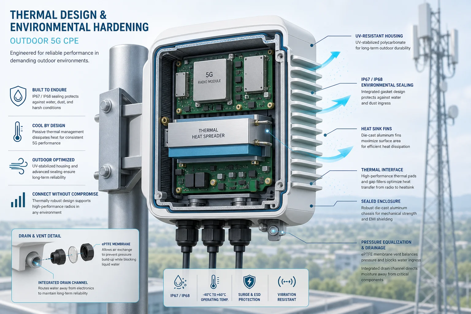
    An outdoor 5G CPE operates in a fundamentally hostile thermal environment. Unlike indoor gateways that sit in air-conditioned rooms, outdoor units face three compounding heat sources simultaneously: solar radiation loading on the enclosure surface (up to 1,000 W/m² at peak), internal heat dissipation from the 5G modem and RF front-end (typically 8–15 W for a Cat 19 modem plus mmWave IF), and ambient air temperatures that can exceed 50°C in direct-sun installations across the Middle East, Africa, and South Asia.

    The result is a junction temperature (Tj) at the modem chipset that can spike well above 105°C — past the safe operating threshold for most commercial 5G SoCs — if thermal management isn’t designed properly from the silicon up. Qualcomm’s X65/X70 modem families specify a maximum Tj of 105°C, while MediaTek’s T750 recommends staying below 100°C for sustained operation. Exceeding these limits triggers automatic CPU throttling, which reduces throughput — sometimes by 40% or more — and accelerates electromigration-related degradation in the chip interconnects over time.

    Passive Cooling Architecture: The Gold Standard for Zero-Maintenance Deployments

    For outdoor CPE, passive cooling is the dominant design choice — and for good reason. Active cooling (fans) introduces a single point of mechanical failure: fan bearings wear out, dust ingress clogs airflow paths, and fan failure in a sealed enclosure often goes undetected until the modem overheats and the subscriber calls support. For a carrier deploying at scale, every active cooling fan in the field is a future truck roll waiting to happen.

    A well-engineered passive cooling system for outdoor 5G CPE relies on four interconnected design elements:

    1. Die-Cast Aluminum Enclosure as Heat Spreader. The enclosure itself becomes the primary heat sink. High-thermal-conductivity die-cast aluminum alloys (ADC12 or A380, with thermal conductivity ~96 W/m·K) are used to spread heat from the internal PCB hot spots — primarily the modem SoC, PMIC, and PA — across the entire enclosure surface. A finned exterior increases the convective surface area by 3× to 5× compared to a smooth wall, dramatically improving passive heat dissipation to ambient air.

    2. Thermal Interface Materials (TIM). The critical interface between the chipset heat spreader and the aluminum enclosure wall. High-performance gap fillers and thermal pads — typically silicone-based materials with 3–6 W/m·K conductivity — bridge the air gap between PCB-mounted components and the enclosure. In best-in-class designs, graphite sheets or vapor chambers are used for hotspot spreading before the heat reaches the enclosure, reducing the thermal resistance by 20–30% compared to direct pad-only coupling.

    3. Internal Air Convection Optimization. Even in a sealed enclosure, internal air circulation matters. Strategic placement of internal baffles and component layout that avoids stagnant air pockets can improve heat transfer to the outer walls by 15–25%. CFD simulation during the mechanical design phase is now standard practice for serious CPE OEMs — it’s the difference between a design that works on paper and one that works in the field.

    4. Solar Radiation Management. The enclosure surface finish matters enormously. A white or light-colored powder-coated aluminum enclosure can reflect 80–85% of incident solar radiation, reducing the solar heat load by over 500 W/m² compared to a dark-colored enclosure. For rooftop and pole-mounted units that cannot avoid direct sun exposure, solar radiation shields — essentially a secondary roof above the main enclosure with an air gap — can reduce internal temperature rise by an additional 8–12°C.

    IP Rating Selection: Matching Protection Level to Deployment Environment

    The IP (Ingress Protection) rating is the most commonly cited environmental specification for outdoor CPE — but it’s also one of the most misunderstood. An IP rating is not a single number and choosing the wrong rating for a given deployment environment can lead to premature field failures.

    IP65 (Dust-tight + Water Jets). Suitable for sheltered outdoor installations — under eaves, in weatherproof cabinets, or pole-mounted with a rain hood. IP65 protects against low-pressure water jets from any direction. It is the minimum acceptable rating for any outdoor CPE deployment, but it is not sufficient for fully exposed installations in high-rainfall regions.

    IP67 (Dust-tight + Temporary Immersion). The sweet spot for most outdoor 5G CPE deployments. IP67 guarantees survival during temporary immersion in up to 1 meter of water for 30 minutes — which covers the worst monsoon flooding scenarios that fixed wireless access operators face in tropical deployment zones. Most carrier RFPs for outdoor CPE now specify IP67 as the baseline requirement.

    IP68 (Dust-tight + Continuous Immersion). Required for deployments in flood-prone areas or installations below ground level. IP68 testing conditions are specified by the manufacturer (not the standard), so procurement teams should verify the exact test parameters — depth and duration — rather than accepting “IP68” at face value. Typical outdoor CPE IP68 ratings specify 1.5–2 meters for 30–60 minutes.

    A critical procurement note: IP rating tests are performed on brand-new units in laboratory conditions. Real-world IP performance degrades over time as gaskets age, UV exposure embrittles seals, and thermal cycling stresses the enclosure. Operators should request accelerated aging test data — specifically 1,000-hour UV exposure and 500-cycle thermal shock testing (-40°C to +85°C) — from CPE vendors before large-scale procurement.

    Conformal Coating and PCB-Level Protection

    Even with an IP67-rated enclosure, condensation remains a threat. Daily thermal cycling — cool nights followed by hot days — causes internal humidity to condense on PCB surfaces. This is where conformal coating becomes essential.

    Conformal coating — typically acrylic, silicone, or parylene — is applied as a thin protective film (25–75 μm) over the PCB assembly. It prevents moisture-induced dendritic growth (electrochemical migration) between adjacent solder pads, which is a leading cause of latent field failures in outdoor electronics.

    For outdoor 5G CPE, silicone-based conformal coatings (SR-type) are preferred over acrylic (AR-type) for three reasons: higher operating temperature tolerance (up to 200°C vs. 125°C), better flexibility during thermal cycling, and superior hydrophobicity that prevents water film formation on coated surfaces. Leading CPE OEMs apply conformal coating using selective robotic spray systems that achieve 100% coverage on both sides of the PCB while leaving connectors and test points masked.

    Field Failure Analysis: What Actually Kills Outdoor CPE

    Field return data from multiple carrier deployments reveals a consistent pattern of outdoor CPE failure modes, ranked by frequency:

    1. Water Ingress (35–40% of field failures). Not catastrophic flooding — slow, cumulative moisture ingress through degraded gaskets, cable gland seals, or UV-damaged enclosure seams. Failures typically appear 18–36 months into deployment, after multiple wet seasons. The root cause is almost always gasket compression set: silicone O-rings that permanently deform under sustained compression and fail to rebound during thermal cycling.
    2. Thermal Throttling-Related Degradation (20–25%). Modems that repeatedly hit Tj limits experience accelerated NBTI (Negative Bias Temperature Instability) in their silicon, leading to gradual timing margin erosion and eventual intermittent failures. These are the hardest failures to diagnose because the unit often works normally when tested in a cooler lab environment.
    3. Lightning-Induced Surge Damage (15–20%). Even with Ethernet surge protection, nearby lightning strikes induce voltage transients on outdoor cabling. IEC 61000-4-5 Class 4 surge immunity (4 kV line-to-ground) is the minimum standard for outdoor CPE in lightning-prone regions. Units with only Class 2 protection (1 kV) show 3× higher field failure rates in tropical deployment zones.
    4. UV Degradation of External Components (10–15%). Plastic radome covers, cable glands, and external antenna connectors degrade under years of UV exposure. Polycarbonate radomes without UV stabilizers can lose 50% of their impact strength within 3 years of tropical sun exposure. Specification of UV-stabilized materials (UV rating F1 per UL 746C) should be mandatory in CPE procurement RFPs.
    5. Connector Corrosion (5–10%). SIM card contacts, Ethernet jack pins, and DC power connectors corrode when even trace amounts of moisture combined with industrial pollutants (sulfur dioxide, hydrogen sulfide) create acidic micro-environments. Gold-flashed contacts with 30 μ” minimum gold thickness over nickel underplate provide the best corrosion resistance for outdoor applications.

    Procurement Checklist: What Operators Should Demand from CPE Vendors

    When evaluating outdoor 5G CPE for large-scale fixed wireless access deployments, procurement teams should require the following environmental qualification data from vendors — not just a datasheet IP rating:

    • Thermal design validation report including CFD simulation results and measured Tj at 55°C ambient under sustained full-load operation (minimum 4-hour soak test)
    • IP rating test certificates from an ISO 17025 accredited laboratory (not self-certified)
    • Accelerated life test data: 1,000-hour damp heat (85°C/85% RH), 500-cycle thermal shock (-40°C to +85°C), 1,000-hour salt spray (ASTM B117)
    • Conformal coating specification with coating type, coverage percentage, and IPC-CC-830 certification
    • Surge immunity test reports per IEC 61000-4-5 at required protection class level
    • UV resistance qualification per UL 746C for all external non-metallic components
    • Gasket material datasheet with compression set values after thermal aging (per ASTM D395 Method B)
    • Field failure rate data from existing deployments in comparable climatic zones, with mean time between failures (MTBF) calculated per Telcordia SR-332 Issue 4

    Deployment Best Practices: Engineering the Installation for Reliability

    Even the best-designed outdoor CPE will fail prematurely if installed incorrectly. Operator field teams should follow these deployment guidelines:

    Cable Drip Loops. Every cable entering the CPE enclosure — Ethernet, DC power, external antenna — must include a drip loop: a U-shaped bend that hangs below the cable entry point. Without a drip loop, rainwater tracks along the cable jacket directly into the gland seal, accelerating moisture ingress. This single practice reduces water-related field failures by an estimated 30–40% across multiple operator deployment audits.

    Orientation and Sun Exposure. Where possible, mount outdoor CPE on north-facing walls (in the northern hemisphere) or with a sun shield. Enclosure surface temperatures on south-facing installations can be 15–20°C higher than north-facing installations at the same ambient temperature. For rooftop deployments where orientation flexibility is limited, specify a solar radiation shield as a mandatory accessory.

    Vented vs. Sealed Installation. Some operators have experimented with Gore-Tex vent plugs that allow pressure equalization while blocking liquid water ingress. These vents reduce the internal pressure differential during thermal cycling, which in turn reduces the mechanical stress on gaskets and seals. Field data suggests vented enclosures show 20–25% lower gasket degradation rates over 3-year deployments, though the vent membrane itself needs periodic replacement in high-dust environments.

    Conclusion: Thermal Design as a Procurement Differentiator

    In the race to deploy 5G fixed wireless access at scale, operators increasingly recognize that outdoor CPE reliability is not a secondary specification — it’s a primary driver of subscriber satisfaction and operational cost. A CPE unit that fails after two rainy seasons costs far more in truck rolls, support calls, and churn than any upfront price saving on the hardware itself. For telecom procurement teams evaluating outdoor 5G CPE, thermal design quality and environmental hardening credentials should carry as much weight in the RFP scoring matrix as throughput, band support, and unit price. Ask for the test data. Visit the reliability lab. Because in outdoor CPE, what’s inside the enclosure determines whether the subscriber stays connected when it matters most.

    Frequently Asked Questions

    Q: What is the minimum IP rating for outdoor 5G CPE in high-rainfall tropical regions?
    A: IP67 is the recommended minimum for fully exposed outdoor installations in tropical and monsoon regions. IP65 is only suitable for sheltered outdoor locations with overhead protection. Operators deploying in flood-prone areas should specify IP68 with documented test parameters (minimum 1.5 m depth for 30 minutes).

    Q: How much does passive cooling add to the unit cost vs. active (fan-based) cooling?
    A: A well-designed die-cast aluminum passive cooling enclosure typically adds $3–7 USD to the BOM cost compared to a stamped sheet metal enclosure with active fan cooling. However, the elimination of fan-related field failures (which account for 15–20% of returns in fan-cooled designs) yields a net TCO reduction of $12–25 per unit over a 5-year deployment lifecycle when truck rolls, replacements, and support costs are factored in.

    Q: Can outdoor CPE be deployed in desert environments with 55°C+ ambient temperatures?
    A: Yes, with proper thermal engineering. Desert-rated outdoor CPE requires enhanced passive cooling surface area (30–50% larger fin area than standard designs), solar radiation shields as mandatory accessories, and chipset-level thermal throttling profiles calibrated for sustained high-ambient operation. Procurement should verify vendor test data at 60°C ambient with 1,000 W/m² simulated solar load — not just 55°C ambient without solar loading.

    Q: What conformal coating type is best for coastal/marine deployment environments?
    A: Parylene (Type XY) coating provides the best protection for coastal and marine environments due to its superior moisture barrier properties, pinhole-free coverage at 5–10 μm thickness, and excellent salt spray resistance. However, parylene is 3–5× more expensive than silicone conformal coating. For most non-marine outdoor deployments, silicone (SR) conformal coating provides adequate protection at a more economical cost point.

  • Edge Computing on 5G CPE: A Technical Guide to MEC Integration, Local Breakout Architecture, and Enterprise Application Hosting for ISPs and System Integrators

    Edge Computing on 5G CPE: A Technical Guide to MEC Integration, Local Breakout Architecture, and Enterprise Application Hosting for ISPs and System Integrators

    As enterprise networks evolve toward distributed architectures and latency-sensitive applications proliferate, the traditional model of backhauling all traffic to a centralized data center or cloud region is reaching its limits. Multi-access Edge Computing (MEC) integrated with 5G CPE represents a paradigm shift — moving compute, storage, and application logic closer to the point of data generation. For ISPs, system integrators, and enterprise telecom buyers, understanding how to architect, deploy, and manage edge-enabled CPE is rapidly becoming a core competency.

    What Is Edge-Enabled 5G CPE?

    Edge-enabled 5G CPE combines the wireless WAN connectivity of a 5G NR modem with onboard compute resources capable of hosting containerized or virtualized application workloads at the network edge. Unlike a traditional CPE that functions purely as a Layer 2/3 forwarding device, edge-enabled CPE includes a general-purpose application processor, local storage, and a software execution environment — typically a lightweight Kubernetes distribution, Docker runtime, or vendor-specific application hosting framework.

    The architectural distinction matters: this is not simply a more powerful router. It is a converged platform where WAN termination, LAN switching, security functions, and third-party application workloads coexist on a single device — managed through orchestration frameworks that span thousands of distributed nodes.

    Key Architectural Components

    1. Local Breakout and Traffic Steering

    Local breakout (also called Local Data Network or LDN in 5G terminology) enables the CPE to route selected traffic flows directly to on-premise or nearby edge infrastructure without traversing the mobile core. This is achieved through ULCL (Uplink Classifier) functionality at the UPF (User Plane Function) level in 5G SA architectures, or through application-level traffic steering policies configured on the CPE.

    The practical benefit is dramatic for latency-sensitive workloads: industrial automation control loops that require sub-5ms round-trip time, real-time video analytics that process multiple 4K streams locally, and AR/VR rendering workloads that cannot tolerate the 20-50ms latency of backhaul to a regional cloud data center.

    2. MEC Application Enablement Platform

    The ETSI MEC reference architecture defines the framework for deploying applications at the network edge. For CPE-level implementation, the MEC platform is often a lightweight software stack that provides:

    • Service Registry and Discovery: Enables edge applications to register their availability and discover peer services without centralized DNS or load balancer dependencies.
    • Radio Network Information Service (RNIS): Exposes real-time RAN-level metrics — signal quality, cell load, UE mobility state — to edge applications, enabling radio-aware application optimization.
    • Location Service: Provides geolocation data without GPS dependency, using cell-ID and NR positioning reference signals.
    • Bandwidth Management Service: Allows applications to request guaranteed throughput allocations from the CPE’s traffic scheduler for deterministic performance.

    3. Container Orchestration at the Far Edge

    Deploying containerized workloads on thousands of distributed CPE devices requires orchestration tooling fundamentally different from data center Kubernetes. Lightweight distributions such as K3s, MicroK8s, and the Linux Foundation’s EdgeX Foundry are purpose-built for resource-constrained edge nodes. Key operational considerations include:

    • Image Distribution Efficiency: P2P image distribution protocols (Dragonfly, Kraken) reduce the bandwidth impact of pushing container images to large CPE fleets over WAN links.
    • Graceful Degradation Under Connectivity Loss: The orchestration layer must maintain application availability during WAN link failures, with local image caches and autonomous scheduling decisions.
    • Resource Quotas and Isolation: Applications must operate within strict CPU, memory, and storage bounds to prevent resource starvation of the CPE’s core networking functions.

    Enterprise Use Cases and Deployment Patterns

    Manufacturing and Industry 4.0

    In smart factory deployments, edge-enabled 5G CPE hosts protocol translation gateways (Modbus TCP to OPC UA, PROFINET to MQTT), local SCADA visualization dashboards, and predictive maintenance inference models running on the device NPU. The CPE becomes the converged connectivity-plus-compute node that bridges operational technology (OT) and information technology (IT) networks without requiring separate industrial PCs at each cell.

    Retail and Branch Office

    Multi-site retail operators deploy edge CPE to host local inventory management applications, real-time video analytics for footfall counting and loss prevention, and digital signage content management — all running locally on the CPE device that also provides the store’s primary WAN connectivity. This eliminates the server closet footprint at each location while improving application responsiveness during WAN congestion or outage events.

    Smart Grid and Utility Networks

    Distribution network operators deploy edge CPE at substations to host local phasor measurement unit (PMU) data aggregation, fault detection algorithms, and demand-response logic. The ultra-low latency of local processing — combined with 5G URLLC connectivity to the central SCADA system — enables grid protection schemes that operate within the IEC 61850 4ms transfer time requirement for GOOSE messages.

    Procurement and Integration Considerations for ISPs

    For ISPs and managed service providers evaluating edge-enabled CPE platforms, the following decision criteria should inform RFP specifications:

    Compute Headroom: Specify minimum available CPU cores and RAM for third-party workloads after accounting for baseline CPE functions (routing, firewall, VPN termination). A 4-core ARM Cortex-A78 with 4GB available RAM for applications is a practical minimum for 2026 enterprise deployments.

    NPU/Accelerator Availability: For AI inference workloads at the edge, integrated neural processing units delivering 6-15 TOPS provide sufficient headroom for common models (object detection, anomaly detection, natural language processing). Verify that the NPU SDK supports common model formats (ONNX, TensorFlow Lite, OpenVINO) and that inference pipelines can coexist with networking workloads without QoS degradation.

    Orchestration Platform Compatibility: The CPE platform should integrate with the operator’s existing device management framework (TR-069 ACS or TR-369 USP controller) for base device lifecycle management, while exposing a separate API or agent for application lifecycle management. Avoid vendor-proprietary application orchestration that locks the operator into a single CPE supplier’s ecosystem.

    Security Isolation: Edge applications must execute in a Trusted Execution Environment (TEE) or hardware-enforced container sandbox that prevents compromised applications from accessing CPE networking functions, subscriber credentials, or other tenants’ data in multi-tenant deployment scenarios. Require vendors to document the security isolation architecture and provide penetration test results for the application hosting environment.

    Zero-Touch Application Provisioning: The ability to deploy, update, and decommission edge applications across a fleet of thousands of CPE devices without manual intervention is critical to operational viability. Evaluate the platform’s support for GitOps-style declarative application state management, canary deployment strategies, and automated rollback on health check failure.

    The ETSI MEC Federation Model

    A emerging architectural pattern is MEC federation, where edge computing resources across multiple administrative domains — operator edge, enterprise on-premise, and hyperscaler edge zones (AWS Wavelength, Azure Edge Zones, Google Distributed Cloud Edge) — are federated into a unified application deployment surface. In this model, the edge-enabled 5G CPE functions as the on-premise node in a hierarchical edge architecture, with workloads able to migrate between CPE, operator MEC, and cloud edge tiers based on latency requirements, resource availability, and cost policies.

    This federation model is particularly relevant for system integrators building multi-site enterprise solutions, where the application deployment topology must flex across hundreds or thousands of locations with heterogeneous edge infrastructure.

    The Road Ahead: 3GPP Release 19 and Beyond

    The 3GPP Release 19 study on “Edge Computing Enhancements” — expected to conclude in Q4 2026 — will introduce standardized APIs for edge application enablement at the 5G system level. Key features under study include:

    • AF-influenced Edge Relocation: Standardized procedures for application function-triggered relocation of edge application contexts between CPE and network edge nodes during UE mobility events.
    • Edge Enabler Client (EEC) on CPE: A standardized client module on the CPE that handles edge service discovery, application context transfer, and capability exposure toward the 5G core network.
    • QoS Monitoring for Edge Applications: Real-time per-flow QoS metrics exposed to edge applications via standardized APIs, enabling adaptive bitrate streaming, dynamic compression level adjustment, and application-level traffic engineering.

    For telecom buyers planning multi-year CPE procurement cycles, selecting platforms with a documented migration path to Release 19 edge computing features — and a silicon roadmap that supports the anticipated compute requirements — is a forward-looking procurement strategy that protects investment in edge-enabled CPE fleets.