Author: openclaw-Lisa-New

  • WiFi 7 for Enterprise Networks: A Telecom Buyer’s Complete Guide to Next-Generation Wireless Infrastructure

    WiFi 7 for Enterprise Networks: A Telecom Buyer’s Complete Guide to Next-Generation Wireless Infrastructure

    The ratification of IEEE 802.11be — commercially known as WiFi 7 — marks the most significant leap in wireless LAN technology in over a decade. With theoretical throughput of up to 46 Gbps, deterministic low-latency operation, and native multi-link aggregation, WiFi 7 is poised to reshape how enterprises, campus environments, and multi-dwelling units (MDUs) approach wireless infrastructure.

    For telecom operators, ISPs, and system integrators, the transition to WiFi 7 is not merely an incremental upgrade. It represents a strategic opportunity to differentiate managed service offerings, reduce wired backhaul dependency, and support high-density applications that WiFi 6 and 6E could not practically deliver. This guide provides a structured evaluation framework for buyers procuring WiFi 7 access points (APs) and converged gateways in 2026.

    What Makes WiFi 7 Different: Technical Foundations

    Before evaluating specific hardware, buyers must understand the three architectural innovations that distinguish WiFi 7 from its predecessors:

    1. 320 MHz Channel Bandwidth

    WiFi 7 doubles the maximum channel width from 160 MHz (WiFi 6/6E) to 320 MHz, available exclusively in the 6 GHz band. This doubling of spectral capacity translates directly to higher throughput, provided sufficient spectrum is available. In regions where regulators have allocated the full 1200 MHz of 6 GHz spectrum (such as the United States, Canada, and South Korea), operators can deploy multiple non-overlapping 320 MHz channels within a single location.

    2. 4K-QAM Modulation

    Quadrature Amplitude Modulation at 4096 points (4K-QAM) packs 12 bits per symbol, compared to 10 bits (1024-QAM) in WiFi 6. This 20% improvement in spectral efficiency requires excellent signal-to-noise ratio (SNR) conditions — typically achievable within 5–8 meters of the AP in open-plan office environments. Enterprise deployments targeting 4K-QAM performance benefit from higher AP density and careful RF planning.

    3. Multi-Link Operation (MLO)

    MLO is arguably WiFi 7’s most transformative feature. It allows a single client device to simultaneously transmit and receive data across multiple frequency bands (2.4 GHz, 5 GHz, and 6 GHz) and channels. This delivers three compounding benefits: aggregate throughput scaling, ultra-low latency through redundant link paths, and seamless band steering without the connection interruption typical of WiFi 6 band steering mechanisms.

    Buyer Evaluation Checklist: 12 Criteria for WiFi 7 AP Selection

    When evaluating WiFi 7 access points and gateways for enterprise or carrier-managed deployments, procurement teams should assess the following dimensions:

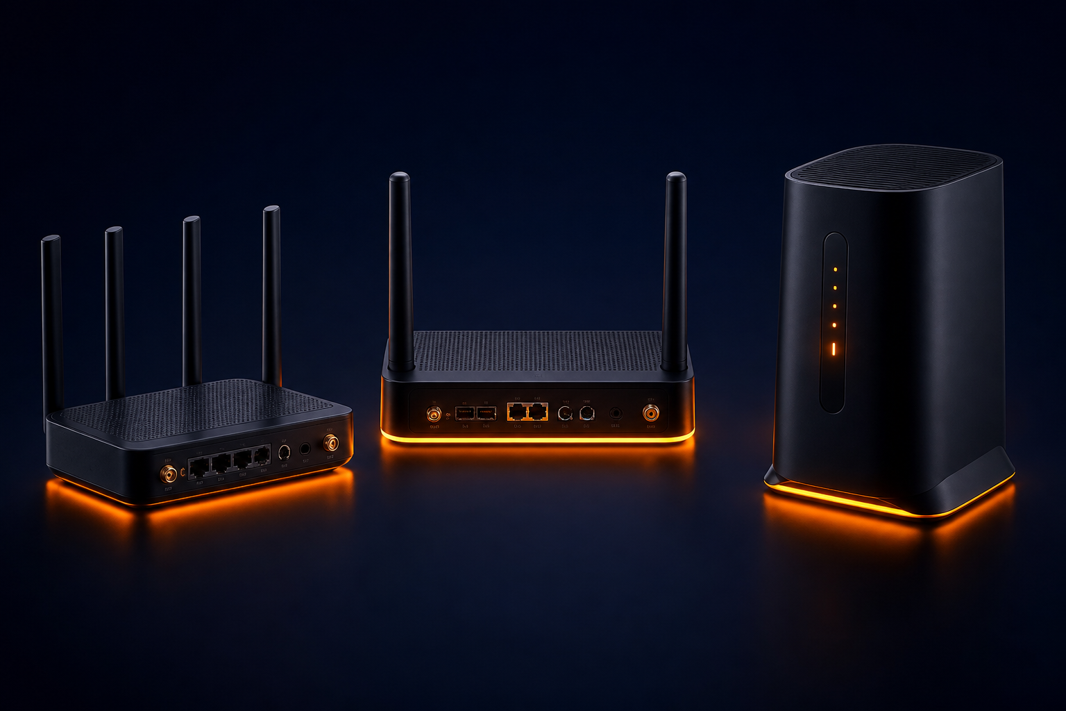
    1. Radio Configuration: Minimum tri-band (2.4 + 5 + 6 GHz) with at least 4×4 MIMO on the 5 GHz and 6 GHz radios. Single-band or dual-band WiFi 7 devices are cost-optimized consumer products unsuitable for enterprise environments.
    2. MLO Implementation: Confirm support for both STR (Simultaneous Transmit and Receive) and NSTR (Non-Simultaneous Transmit and Receive) MLO modes. STR MLO provides the highest throughput; NSTR MLO is simpler to implement but offers fewer latency benefits.
    3. Backhaul Interfaces: Enterprise APs should offer at least one 10G Ethernet port (RJ45 or SFP+) for uplink. 2.5G Ethernet is acceptable for SME-focused products but will become a bottleneck in high-density deployments.
    4. Power over Ethernet (PoE): PoE++ (802.3bt, Type 4, up to 90W) is strongly recommended for tri-band 4×4 WiFi 7 APs. PoE+ (802.3at, 30W) may force the AP to reduce transmit power or disable a radio, negating WiFi 7 benefits.
    5. Channel Planning Tools: Built-in or cloud-managed automatic frequency coordination (AFC) for 6 GHz operation is essential in regions requiring AFC compliance for standard-power APs.
    6. Client Density Support: Look for vendor-published metrics on concurrent client capacity (minimum 512 clients per radio) and airtime fairness algorithms validated for mixed WiFi 6/6E/7 client environments.
    7. Security: WPA3-Enterprise with 192-bit encryption is mandatory. Additional features such as Protected Management Frames (PMF), RADIUS CoA support, and DPP (WiFi Easy Connect) for headless IoT onboarding add enterprise value.
    8. Management Platform: Evaluate on-premises controller vs. cloud-managed options. For ISP-managed services, cloud platforms with multi-tenancy, zero-touch provisioning, and REST API integration into existing OSS/BSS systems are strongly preferred.
    9. Spectrum Intelligence: Real-time spectrum analysis, interference classification, and automated channel optimization using AI/ML models are differentiators in dense urban deployments.
    10. IoT Radio Coexistence: Integrated Zigbee, Thread, or Bluetooth 5.4 radios for IoT gateway functionality reduce the need for separate IoT infrastructure.
    11. Regulatory Certification: Verify FCC (US), CE (EU), MIC (Japan), and SRRC (China) certifications for the target deployment region. WiFi 7 certification from the Wi-Fi Alliance should be current.
    12. Vendor Roadmap and Supply Assurance: Assess the manufacturer’s commitment to firmware updates, security patch SLAs, and component sourcing resilience. For ODM-sourced hardware, validate that the design is under active development rather than a one-time reference design adaptation.

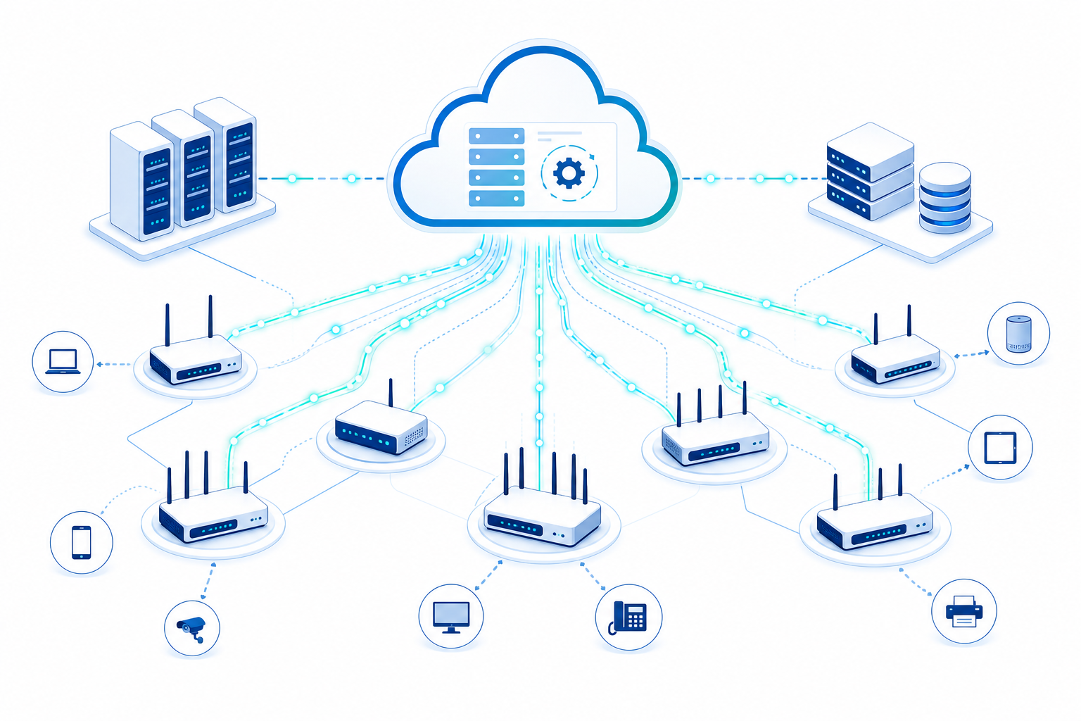
    Deployment Architecture: Converged Gateway vs. Distributed AP

    A key architectural decision for telecom buyers is whether to deploy converged CPE gateways with integrated WiFi 7 or separate wired gateway + distributed AP topologies. The right choice depends on the deployment scenario:

    • Converged Gateway (CPE + WiFi 7): Best suited for SOHO, SME, and MDU deployments where simplicity, single-vendor support, and reduced cabling are priorities. Modern 5G FWA + WiFi 7 converged gateways can serve as the sole connectivity appliance for small offices.
    • Distributed AP Topology: Preferred for campus, hospitality, and large enterprise deployments requiring uniform coverage across thousands of square meters. A wired gateway (or SD-WAN appliance) serves as the network edge, with multiple WiFi 7 APs providing access-layer connectivity.

    For operators offering managed WiFi services to business customers, a hybrid approach is increasingly common: a WiFi 7 mesh system with wired backhaul between APs, managed through a single cloud controller, with the gateway function located at the primary AP or a dedicated edge device.

    Cost Considerations and ROI

    WiFi 7 enterprise AP pricing in mid-2026 typically ranges from $350 to $1,200 USD per unit, depending on radio configuration, MLO capability, and management platform licensing. While this represents a 25–40% premium over equivalent WiFi 6E APs, the total cost of ownership (TCO) analysis should consider:

    • AP Density Reduction: The 320 MHz channel width and improved spectral efficiency of WiFi 7 can reduce required AP count by 15–25% compared to WiFi 6 in equivalent coverage areas, partially offsetting the per-unit premium.
    • Future-Proofing: Deploying WiFi 7 in 2026 provides a 5–7 year technology lifecycle, avoiding a costly mid-cycle upgrade from WiFi 6E to WiFi 7 in 2028–2029.
    • Service Revenue Upside: Operators offering managed WiFi 7 as a premium tier can command 20–30% higher monthly recurring revenue per subscriber compared to WiFi 6 managed services.

    FAQ

    Is WiFi 7 backward compatible with WiFi 6 and WiFi 5 clients?

    Yes. WiFi 7 access points are fully backward compatible with 802.11a/b/g/n/ac/ax (WiFi 6) clients. However, to realize WiFi 7 benefits (320 MHz, 4K-QAM, MLO), both the AP and client device must support WiFi 7. Mixed-client environments operate in compatibility mode, which may reduce peak throughput for WiFi 7 clients.

    When should an operator begin deploying WiFi 7 instead of WiFi 6E?

    Operators should begin WiFi 7 procurement and lab testing in Q3 2026 for production deployments starting Q4 2026. WiFi 6E remains a cost-effective choice for budget-sensitive deployments where 6 GHz spectrum access is the primary requirement, but the performance and efficiency advantages of WiFi 7 justify the premium for greenfield enterprise deployments.

    What is the realistic throughput of WiFi 7 in enterprise deployments?

    While the theoretical maximum is 46 Gbps, real-world enterprise throughput for a tri-band 4×4 WiFi 7 AP with MLO enabled typically ranges from 8–15 Gbps aggregate across all bands, depending on client count, distance, and RF environment. Single-client peak throughput under optimal conditions (320 MHz channel, 4K-QAM, MLO) can reach 5–7 Gbps.

    Does WiFi 7 require new cabling infrastructure?

    For most deployments, existing Cat 6A cabling is sufficient, as 10GBASE-T operates reliably over Cat 6A at distances up to 100 meters. Sites with older Cat 5e cabling may require upgrades to support multi-gigabit backhaul. Power delivery via PoE++ (802.3bt) requires Cat 6A or better cabling for full-power operation at extended distances.

    Planning a WiFi 7 deployment for your enterprise or managed service customers? Honlly Telecom supplies carrier-grade WiFi 7 access points, converged 5G FWA + WiFi 7 gateways, and custom ODM solutions for operators worldwide. Get in touch with our engineering team to discuss your requirements.

  • eSIM Technology Reshapes Fixed Wireless Access: How eUICC-Enabled CPE Is Simplifying Global Operator Deployments in 2026

    eSIM Technology Reshapes Fixed Wireless Access: How eUICC-Enabled CPE Is Simplifying Global Operator Deployments in 2026

    The fixed wireless access (FWA) market has matured rapidly over the past three years, with global 5G FWA subscriptions now exceeding 20 million. Behind this growth lies a less visible but equally significant shift: the transition from traditional removable SIM cards to embedded SIM (eSIM) and eUICC (embedded Universal Integrated Circuit Card) technology in customer premises equipment (CPE).

    For telecom operators, ISPs, and MVNOs managing multi-country deployments, eUICC-enabled CPE represents more than a hardware simplification. It is a logistics multiplier that can reduce time-to-market, eliminate physical SIM handling, and enable remote subscriber provisioning (RSP) across different mobile network operators (MNOs).

    The eUICC Advantage in FWA Deployments

    Traditional FWA CPE relies on physical SIM cards that must be manufactured, shipped, inserted, and activated for each device. In a large-scale deployment involving tens of thousands of units across multiple countries, the operational friction is substantial. eUICC technology eliminates this physical dependency.

    With GSMA-compliant RSP, operators can provision SIM profiles over-the-air (OTA) after the CPE has been installed at the end-user location. This means a single SKU can serve multiple markets, with the appropriate operator profile downloaded based on geographic location, signal quality, or commercial agreement. For distributors and system integrators managing inventory across regions, this dramatically simplifies warehousing and logistics.

    Key Deployment Scenarios

    Several operators in Europe and Asia-Pacific have begun deploying eUICC FWA CPE in production networks. The primary use cases include:

    • Multi-IMSI Roaming: CPE devices pre-loaded with multiple international mobile subscriber identities (IMSI) can switch between partner networks based on signal strength or cost optimization, ensuring service continuity for enterprise customers.
    • Cross-Border Deployments: For operators serving border regions or multinational enterprise clients, eSIM allows a single device model to connect to different MNOs on either side of a border without hardware changes.
    • MVNO Enablement: Mobile virtual network operators can rapidly onboard subscribers by remotely provisioning their own profiles onto eUICC CPE without negotiating physical SIM distribution agreements.
    • IoT and Private 5G Integration: Fixed wireless gateways serving industrial IoT or private 5G networks benefit from eSIM flexibility when transitioning between public and private network identities.

    Market Momentum and Standards

    The GSMA SGP.22 (M2M) and SGP.32 (IoT) specifications have matured to support consumer and industrial eSIM profiles. In parallel, chipset vendors including Qualcomm and MediaTek have integrated eUICC support into their 5G modem platforms — the same platforms powering modern FWA CPE from OEM/ODM manufacturers in Asia.

    According to industry data, eSIM-capable device shipments are projected to exceed 3.5 billion units annually by 2027, with FWA CPE comprising a growing share. The GSMA estimates that over 400 mobile operators worldwide now support eSIM services, creating a broad ecosystem for eUICC-enabled fixed wireless equipment.

    OEM Readiness and Supply Chain Implications

    For the OEM/ODM manufacturing sector — particularly in Shenzhen and Xiamen, where a significant portion of global FWA CPE is produced — eUICC integration is becoming a standard requirement in RFQs from tier-1 operators. Manufacturers that have pre-certified their designs with major eUICC platform providers (such as Thales, G+D, and IDEMIA) hold a competitive advantage in operator tenders.

    Honlly Telecom has observed a 40% increase in operator inquiries specifying eSIM-ready CPE over the past twelve months, with particular demand from European operators preparing for multi-country 5G FWA rollouts under the Digital Decade 2030 framework. The ability to ship a single hardware variant configurable for any target market is becoming a procurement requirement rather than a nice-to-have feature.

    Challenges and Considerations

    Despite clear advantages, eUICC adoption in FWA is not without challenges. Interoperability testing between eUICC profiles and modem firmware requires close collaboration between chipset vendors, CPE manufacturers, and SIM platform providers. Regulatory frameworks for permanent roaming and cross-border profile switching vary by jurisdiction, and operators must navigate these carefully.

    Additionally, the per-unit BOM cost increase for eUICC integration — typically $2–5 USD depending on the secure element implementation — must be weighed against logistics savings and operational flexibility. For large-scale deployments exceeding 100,000 units, the logistics savings alone typically justify the hardware premium within the first year of operation.

    FAQ

    What is the difference between eSIM and eUICC?

    eSIM refers to the physical embedded SIM hardware soldered onto the device PCB. eUICC is the software architecture that enables remote SIM profile management — downloading, enabling, disabling, and deleting operator profiles OTA. A device can have an eSIM that is not eUICC-compliant, though most modern implementations combine both.

    Can existing FWA CPE be retrofitted with eSIM?

    Generally no. eSIM requires dedicated hardware (soldered secure element) and modem firmware support. Retrofitting would require hardware redesign. However, some manufacturers offer dual-SIM designs (one physical SIM slot + one eSIM) for transitional deployments.

    How does eUICC affect certification timelines?

    eUICC CPE must undergo additional GCF/PTCRB certification for the eSIM component. However, because a single hardware design can serve multiple operators, the total certification burden across markets is often lower compared to maintaining separate SKUs with different physical SIM configurations.

    Which operators are leading eSIM FWA deployments?

    European operators including Deutsche Telekom, Vodafone, and Orange have active eSIM FWA programs. In North America, T-Mobile has deployed eSIM-capable FWA CPE for its 5G Home Internet service. Multiple operators in Japan, Australia, and the Middle East are following with commercial launches planned for late 2026.

    Looking for eSIM-ready 5G FWA CPE for your network deployment? Honlly Telecom offers eUICC-enabled fixed wireless access devices with multi-IMSI support and GSMA-compliant remote SIM provisioning. Contact our team today to discuss your requirements.

  • Spectrum Refarming Economics for Regional Operators: CPE Compatibility Planning and Migration Strategies for the 3G Sunset to 5G NR Transition

    Spectrum Refarming Economics for Regional Operators: CPE Compatibility Planning and Migration Strategies for the 3G Sunset to 5G NR Transition

    As the global 3G sunset accelerates and 4G spectrum is progressively refarmed for 5G New Radio (NR), regional telecom operators face complex decisions about CPE fleet compatibility, investment timing, and subscriber migration strategy. With over 90 operators worldwide having announced 3G shutdowns and many now planning 4G spectrum refarming in low and mid-bands, understanding the CPE implications is critical for network planners and procurement teams.

    The Spectrum Refarming Landscape in 2026

    Spectrum refarming — the reallocation of frequency bands from legacy technologies to newer ones — is accelerating across three dimensions in 2026:

    • 3G Sunset Completion: With 2100 MHz (Band 1) and 900 MHz (Band 8) now fully refarmed to 4G LTE or 5G NR in most of Europe, Asia-Pacific, and North America, operators are redirecting these bands for 5G low-band coverage layers. CPE that only supports 3G on these bands is no longer deployable.
    • 4G LTE Spectrum Reallocation: A growing number of operators are refarming 1800 MHz (Band 3) and 2600 MHz (Band 7) from LTE-only to dynamic spectrum sharing (DSS) between 4G and 5G NR. In markets with mature 5G adoption, entire LTE carriers are being converted to 5G NR-only operation.
    • Sub-1 GHz 5G Expansion: The 600 MHz (Band 71) and 700 MHz (Band 28) bands — historically reserved for broadcast or LTE coverage — are increasingly allocated to 5G NR for deep indoor and rural coverage, requiring CPE with extended low-band NR support.

    CPE Compatibility Risks During Spectrum Transitions

    Operators managing heterogeneous CPE fleets face several compatibility risks during spectrum refarming transitions:

    Band Support Gaps

    Legacy LTE Cat-4 CPE devices often support a limited band set — typically B1/B3/B7/B8/B20 in EMEA markets. When an operator refarms B3 for 5G NR, these devices lose their primary capacity band and may fall back to congested B20 (800 MHz), resulting in severe throughput degradation. Operators should audit CPE fleet band support against their 3-5 year spectrum roadmap before bulk purchasing decisions.

    DSS Interoperability

    Dynamic Spectrum Sharing allows 4G and 5G to coexist on the same frequency band, but CPE modem firmware must correctly handle DSS scheduling. Older LTE chipsets — particularly those based on Qualcomm X5/X7 or MediaTek T750 platforms — may exhibit reduced throughput or connection instability in DSS environments. Operators should require DSS interoperability test reports from CPE suppliers for any device intended for DSS-deployed bands.

    5G SA vs. NSA Dependency

    Non-Standalone (NSA) 5G CPE requires an LTE anchor band for control plane signaling. If an operator refarms the LTE anchor band (typically B3 or B7) to 5G NR-only operation, NSA CPE loses connectivity entirely. The transition path is to 5G Standalone (SA) CPE that operates independently of LTE — but SA-capable chipsets carry a BOM cost premium, and many early 5G CPE deployments were NSA-only. Operators with NSA-dominant fleets must plan SA migration before refarming LTE anchor bands.

    Economic Decision Framework for Regional Operators

    The decision to proactively replace CPE ahead of spectrum refarming versus waiting for natural device churn involves trade-offs:

    • Subscriber Experience Risk: Allowing CPE to degrade to a single low-band carrier after refarming can increase churn. The cost of subscriber acquisition typically exceeds CPE replacement cost by a factor of 3-5x in competitive markets.
    • Bulk Procurement Economics: Ordering CPE in volumes of 10,000+ units reduces per-unit cost by 15-25% versus smaller replenishment orders. Operators with upcoming spectrum changes should time bulk purchases to coincide with refarming milestones.
    • Trade-In Programs: Several operators in Europe and Southeast Asia have successfully implemented CPE trade-in programs, offering subscribers a discounted 5G CPE upgrade in exchange for returning legacy 4G devices. The returned devices can be refurbished for markets with later refarming timelines or sold into secondary markets.
    • Multi-Band Future-Proofing: Selecting CPE with broad band support — covering B1/B3/B5/B7/B8/B20/B28/B38/B40/B41 as a minimum for global deployment — reduces spectrum refarming risk. The incremental BOM cost for additional band support in modern RF front-end modules is modest, typically $1.50-3.00 per device.

    Migration Strategy Recommendations

    For regional operators planning spectrum refarming within the next 12-24 months, we recommend a phased approach:

    Phase 1 — Fleet Audit (Months 1-3): Inventory all deployed CPE by model, chipset generation, and band support. Identify devices that will lose their primary capacity band after planned refarming. Map each device model to a migration action: retain, firmware-upgrade for DSS, or replace.

    Phase 2 — New Procurement Specification (Months 3-6): Update CPE procurement specifications to require 5G SA support, broad sub-6 GHz band coverage including all planned NR bands, DSS interoperability certification, and eSIM support for flexible operator profile management during transition periods.

    Phase 3 — Subscriber Migration (Months 6-18): Execute targeted CPE replacement for at-risk subscribers, prioritizing those in areas where LTE capacity bands are being refarmed first. Use ACS-based remote management to push configuration updates to DSS-capable devices. Implement trade-in programs to accelerate voluntary upgrades.

    Frequently Asked Questions

    How do I know if my existing CPE fleet will be affected by spectrum refarming?

    Conduct a fleet audit cross-referencing each CPE model’s supported frequency bands against your spectrum refarming roadmap. Devices that rely on bands scheduled for refarming as their primary capacity layer are at risk. Your CPE supplier should provide band support matrices and modem firmware capabilities for each model.

    Can firmware updates extend CPE compatibility with refarmed spectrum?

    Firmware updates can improve DSS interoperability and enable new band combinations on modems that already have the necessary RF hardware support. However, firmware cannot add frequency band support that the RF front-end hardware does not physically support. Hardware band support is determined by the RF filters, power amplifiers, and antenna matching circuitry designed into the device.

    What is the typical lead time for CPE orders during a spectrum transition?

    Standard CPE orders typically require 4-8 weeks for production and shipping, but customized SKUs with specific band combinations or firmware requirements may require 10-14 weeks. Operators should plan procurement at least 4-6 months ahead of planned refarming dates to avoid supply chain delays during industry-wide transition periods.

    Planning a spectrum refarming transition? Honlly Telecom provides multi-band, future-proofed CPE with broad sub-6 GHz coverage and DSS-validated firmware. Request a consultation with our engineering team →

  • Zero-Touch Provisioning Architecture for ISP CPE Rollouts: A Technical Guide to Automated Device Onboarding, ACS Integration, and Fleet Management at Scale

    Zero-Touch Provisioning Architecture for ISP CPE Rollouts: A Technical Guide to Automated Device Onboarding, ACS Integration, and Fleet Management at Scale

    For ISPs and telecom operators managing thousands of customer premises equipment (CPE) units, the manual configuration of each device represents one of the largest operational cost centers. Zero-touch provisioning (ZTP) — the ability to automatically configure and activate CPE upon first connection without any field technician or end-user intervention — has evolved from a nice-to-have feature to a competitive necessity in 2026. This guide examines the architecture, protocols, and vendor selection criteria for deploying ZTP at scale.

    What Is Zero-Touch Provisioning for CPE?

    Zero-touch provisioning is an automated device onboarding workflow where a CPE unit, upon initial power-up and internet connectivity, automatically discovers its management server, authenticates itself, downloads configuration parameters, and becomes operational without human intervention. The process typically completes within minutes and covers firmware version verification, WAN/LAN interface configuration, Wi-Fi SSID and security setup, VoIP SIP account provisioning, and service-specific VLAN assignments.

    The ZTP Architecture: Core Components

    A production-grade ZTP system for ISP-scale CPE deployments consists of four integrated components:

    1. Auto-Configuration Server (ACS)

    The ACS is the central management platform that communicates with CPE devices. Modern deployments use TR-069 (CWMP) for legacy fleet management and TR-369 (User Services Platform/USP) for new device onboarding. USP offers significant advantages: WebSocket-based always-on connections replacing periodic TR-069 Inform messages, support for MQTT message brokers for IoT-scale deployments, and a more efficient data model based on the Broadband Forum’s Device:2.16 root data model. When selecting an ACS, operators should verify multi-vendor CPE support, horizontal scalability for 100,000+ device fleets, and API-driven integration with existing OSS/BSS systems.

    2. Bootstrapping and Device Identity

    Every ZTP workflow begins with device identity. CPE must present a unique, cryptographically verifiable identity to the ACS before receiving configuration. Common approaches include: X.509 device certificates burned into factory firmware, IMEI-based identification with pre-provisioned ACS URL via DHCP Option 43, and SZTP (RFC 8572) bootstrapping for secure zero-touch onboarding in multi-vendor environments. Manufacturers that pre-load device certificates and ACS URLs into firmware significantly reduce operator integration effort — a key differentiator in CPE supplier selection.

    3. Configuration Template Engine

    Rather than configuring each device individually, ZTP systems use parameterized configuration templates. A single template defines the standard configuration for a device class (e.g., “Residential FWA CPE — Region A”), with variables populated from the subscriber management database during provisioning. Template variables typically include WAN IP assignment mode, PPPoE credentials or DHCP settings, Wi-Fi SSID and WPA3 passphrase, VoIP SIP credentials, and QoS policy references. Operators should require that CPE vendors support the Broadband Forum’s TR-181 Device Data Model to ensure template portability across hardware generations.

    4. Firmware Lifecycle Management

    ZTP extends beyond initial configuration to ongoing firmware management. During provisioning, the ACS should verify the device firmware version against a defined minimum baseline template. If the firmware is outdated, the ZTP workflow pauses configuration, triggers a firmware upgrade, reboots the device, and then resumes provisioning. This ensures every deployed CPE runs a known-good firmware version before entering service — critical for security compliance and feature consistency across the fleet.

    Vendor Selection Criteria for ZTP-Ready CPE

    When evaluating CPE suppliers for ZTP-enabled deployments, ISP procurement teams should assess these capabilities:

    • TR-069/TR-369 Protocol Support: Does the CPE support both CWMP and USP? Is the USP agent conformant with Broadband Forum TP-469 Conformance Test Plan?
    • Factory Certificate Provisioning: Can the manufacturer pre-load device certificates and ACS bootstrap URLs during production?
    • TR-181 Data Model Coverage: What percentage of the TR-181 Device:2 root data model is implemented? Critical objects include Device.WiFi., Device.Ethernet., Device.IP., and Device.QoS.
    • ACS Interoperability Testing: Has the supplier tested interoperability with leading ACS platforms (Axiros, Friendly Technologies, AVSystem, Incognito)?
    • Customization Flexibility: Can the manufacturer customize the default configuration file, firmware splash page, and bootstrap URL per operator requirements?
    • Bulk Provisioning API: Does the supplier provide tools or APIs for bulk device pre-provisioning — uploading IMEI/Serial-to-subscriber mappings before shipment?

    Deployment Best Practices

    Operators implementing ZTP at scale should follow these practices: begin with a staged rollout — a small pilot fleet of 500-1,000 devices to validate the full ZTP workflow before scaling. Define clear provisioning state machines with timeout and retry logic for each step. Monitor provisioning success rates by device model, firmware version, and geographic region to identify patterns in failures. Maintain a fallback manual provisioning path for edge cases — approximately 2-5% of devices will require human intervention even in mature ZTP deployments. Finally, require that CPE vendors provide a dedicated engineering contact for ZTP integration support during the initial deployment phase.

    Frequently Asked Questions

    What is the difference between TR-069 and TR-369 for ZTP?

    TR-069 (CWMP) uses periodic HTTP-based inform messages initiated by the CPE, creating a polling-based communication model. TR-369 (USP) uses persistent WebSocket connections initiated by the CPE agent, allowing the ACS to push configuration changes and firmware updates in real time. USP also supports MQTT as a transport protocol for IoT-scale device fleets and provides a more granular, efficient data model.

    How long does a typical ZTP process take?

    A well-optimized ZTP workflow typically completes within 3-8 minutes from device power-on to operational service, including DHCP acquisition, ACS discovery, configuration download, and service activation. Firmware upgrades during provisioning add 2-5 minutes depending on image size and connection speed.

    Can ZTP work without an ACS?

    Lightweight ZTP can be achieved without a full ACS using DHCP options to deliver a configuration file URL or by pre-loading configuration into device firmware. However, these approaches lack the ongoing management, monitoring, and firmware lifecycle capabilities of an ACS-managed deployment and are suitable only for small-scale or single-purpose deployments.

    Planning a large-scale CPE deployment? Honlly Telecom offers ZTP-ready devices with pre-loaded certificates, ACS interoperability testing, and dedicated integration support. Contact our engineering team →

  • Global MVNO Market Surpasses $100 Billion Valuation in 2026: CPE Customization Requirements for Virtual Network Operators Scaling Enterprise Services

    Global MVNO Market Surpasses $100 Billion Valuation in 2026: CPE Customization Requirements for Virtual Network Operators Scaling Enterprise Services

    The global Mobile Virtual Network Operator (MVNO) market has crossed the $100 billion valuation threshold in 2026, driven by enterprise digital transformation, IoT connectivity demand, and the expanding 5G wholesale access market. For CPE manufacturers, this milestone signals a fundamental shift in device requirements: MVNOs need customizable, brand-ready customer premises equipment that can be rapidly deployed across multiple host operator networks.

    The MVNO Growth Trajectory: $100B and Accelerating

    According to GSMA Intelligence and multiple industry analyst reports, the global MVNO market reached an estimated $102 billion in revenue during the first half of 2026, with a compound annual growth rate exceeding 8.5% since 2023. Key growth drivers include:

    • Enterprise MVNOs: Large corporations launching private-branded mobile services for employees and IoT fleets, requiring customized CPE with enterprise-grade management features.
    • IoT-Focused MVNOs: Specialized operators serving smart metering, fleet telematics, and industrial sensor networks, demanding ruggedized routers with low-power wide-area connectivity.
    • 5G Wholesale Expansion: MNOs increasingly opening 5G Standalone (SA) cores to MVNO partners, enabling differentiated network slicing and QoS-tiered CPE offerings.
    • Regulatory Support: Markets including the EU, Southeast Asia, and Latin America continue mandating MVNO access as a competition-enhancing measure.

    CPE Implications: What MVNO Buyers Need from Device Suppliers

    Unlike traditional MNOs that order CPE in standardized, carrier-branded configurations, MVNOs present distinct device requirements that CPE manufacturers must address:

    1. Multi-IMSI and Multi-PLMN Support

    MVNOs frequently operate across multiple host networks and geographies. CPE must support multi-IMSI profiles — ideally with eSIM/eUICC capability — allowing devices to switch between host operator profiles based on coverage, cost, or service-level agreements. This requires modem firmware flexibility and GSMA SGP.02/SGP.22 compliant eSIM architectures.

    2. White-Label Branding and Customizable UI

    MVNOs sell under their own brand identity, not the host MNO’s. CPE must support white-label device firmware with customizable web UI branding, logo placement, SSID defaults, and packaging design. Manufacturers offering OEM/ODM flexibility with low minimum order quantities for branded firmware gain significant competitive advantage in the MVNO segment.

    3. Remote Provisioning and Zero-Touch Deployment

    MVNOs typically lack the field engineering resources of MNOs. CPE must support TR-069/TR-369 auto-configuration server (ACS) integration, allowing subscriber devices to be provisioned remotely upon first power-on. Zero-touch onboarding reduces operational costs and subscriber churn — critical metrics for margin-sensitive MVNOs.

    4. Flexible APN and PDP Context Configuration

    MVNOs often use their own Access Point Name (APN) configurations that route traffic through MVNO core network elements before reaching the host MNO’s packet gateway. CPE must support multiple APN profiles, dynamic PDP context activation, and VLAN tagging for service differentiation — features that enable MVNOs to offer tiered data plans and managed SD-WAN services.

    5. Cost-Optimized Hardware Platforms

    MVNOs operate on thinner margins than facility-based operators. CPE hardware must balance performance with aggressive BOM cost targets. Cat-4 and Cat-6 LTE platforms remain dominant in MVNO deployments, with Cat-12 gaining traction in markets where 5G wholesale access remains cost-prohibitive. Modular RF design — allowing the same enclosure to serve 4G and 5G variants — is increasingly valued.

    Regional Hotspots for MVNO CPE Demand

    • Europe: Mature MVNO ecosystem; eSIM-capable CPE demand driven by cross-border IoT and roaming-intensive enterprise services.
    • Southeast Asia: Rapidly growing MVNO segment in Indonesia, Philippines, and Thailand; demand for affordable LTE Cat-4/Cat-6 fixed wireless CPE.
    • Latin America: Regulatory-driven MVNO expansion in Brazil and Mexico; need for multi-band LTE routers supporting regional frequency bands (B2, B4, B5, B7, B28).
    • Middle East & Africa: MVNOs serving migrant communities and enterprise connectivity; demand for portable MiFi and desktop CPE with long battery life.

    Strategic Outlook for CPE Manufacturers

    The MVNO segment represents a high-volume, recurring-revenue opportunity for CPE suppliers. To capture this market, manufacturers should invest in: flexible firmware platforms supporting multi-tenant branding, eSIM-ready hardware designs, simplified TR-069/TR-369 provisioning profiles, and SKU rationalization that serves both MNO and MVNO requirements from common hardware platforms. As 5G SA wholesale access matures through 2027-2028, MVNOs will increasingly demand 5G CPE with network slicing awareness — a capability that early-moving manufacturers can build into their product roadmaps today.

    Frequently Asked Questions

    What types of CPE do MVNOs typically purchase?

    MVNOs primarily purchase LTE Cat-4 and Cat-6 fixed wireless CPE, portable MiFi devices, and USB dongles. Enterprise-focused MVNOs also procure industrial-grade routers with multi-WAN failover. The common requirement across all categories is support for multiple host operator profiles and remote device management.

    How does MVNO CPE differ from standard MNO CPE?

    The key differences are: white-label branding capability, multi-IMSI/eSIM support for host operator switching, simplified zero-touch provisioning, and cost-optimized hardware designs. MVNOs also require more flexible APN and data routing configurations than single-operator MNOs.

    What is the minimum order quantity for MVNO-branded CPE?

    Minimum order quantities vary by manufacturer. Honlly Telecom offers flexible OEM/ODM programs with competitive MOQs for MVNO customers, including customized firmware branding and packaging. Contact our sales team for a project-specific quotation.

    Looking for MVNO-optimized CPE solutions? Contact Honlly Telecom to discuss your device requirements — from customized firmware to flexible order quantities. Get in touch with our team →

  • 5G FWA and Wi-Fi 7 Convergence: Architectural Strategies for Multi-Gigabit Indoor Coverage in MDU and Enterprise Deployments

    5G FWA and Wi-Fi 7 Convergence: Architectural Strategies for Multi-Gigabit Indoor Coverage in MDU and Enterprise Deployments

    The convergence of 5G Fixed Wireless Access and Wi-Fi 7 represents the most significant architectural shift in broadband CPE design since the introduction of integrated DOCSIS-Wi-Fi gateways. For operators deploying FWA services to multi-dwelling units (MDUs), enterprise campuses, and dense urban environments, the end-to-end interaction between the 5G WAN link and the Wi-Fi 7 indoor distribution layer determines whether subscribers experience the multi-gigabit performance that 5G-Advanced networks can deliver. This analysis examines the architectural considerations, trade-offs, and deployment strategies for converged 5G FWA + Wi-Fi 7 CPE platforms.

    The Bottleneck Problem: Why Wi-Fi 6E Is Not Enough for 5G-Advanced FWA

    5G-Advanced networks based on 3GPP Release 18 specifications are delivering peak downlink speeds of 5-8 Gbps in commercial FWA deployments, with 10 Gbps expected as carrier aggregation configurations expand to 6-8 component carriers and 256-QAM modulation becomes standard on the downlink. However, the indoor distribution layer — traditionally a Wi-Fi 6E access point operating in 160 MHz channels with 1024-QAM — caps per-client throughput at approximately 1.2-1.8 Gbps under ideal conditions. For a single-user scenario where the subscriber’s primary device needs to access the full WAN capacity, Wi-Fi 6E becomes the binding constraint.

    Wi-Fi 7 addresses this bottleneck through three mechanisms working in concert: 320 MHz channel bandwidth (doubling the spectral resource), 4K-QAM modulation (20% more bits per symbol), and Multi-Link Operation (aggregating throughput across frequency bands). A triband Wi-Fi 7 CPE with STR-MLO can deliver 4.5-5.2 Gbps to a single Wi-Fi 7 client — approaching parity with the 5G-Advanced downlink capacity and effectively removing the indoor distribution bottleneck for all current and near-term FWA deployment scenarios.

    Architectural Models for Converged 5G FWA + Wi-Fi 7 CPE

    Model 1: Integrated Single-Box CPE

    The integrated single-box approach combines the 5G modem, Wi-Fi 7 access point, and Ethernet switch in a single enclosure. This is the dominant architecture for residential and SMB FWA deployments, accounting for approximately 85% of operator CPE shipments in 2026 according to Omdia.

    Advantages: Lowest BOM cost, simplest installation (single power supply, single device to provision), unified device management via TR-369 USP or TR-069, and simplified subscriber support. The integrated thermal design can share heatsink and ventilation resources between the 5G modem and Wi-Fi 7 subsystems.

    Disadvantages: Fixed physical placement — the optimal location for 5G reception (typically near a window with line-of-sight to the gNodeB) may not be the optimal location for Wi-Fi coverage (typically central to the living or working space). Single-box designs also face thermal density challenges, with combined modem + Wi-Fi 7 power consumption reaching 35-45W in premium implementations, requiring active cooling in some form factors.

    Model 2: Split Architecture (Outdoor CPE + Indoor Wi-Fi 7 Unit)

    The split architecture places the 5G modem and high-gain directional antenna in an outdoor unit (ODU), typically IP67-rated and pole or wall-mounted, connected to an indoor Wi-Fi 7 unit via Power over Ethernet (PoE) or fiber. This architecture is increasingly specified for MDU and enterprise FWA deployments where outdoor antenna placement significantly improves 5G signal quality.

    Advantages: The ODU can be placed at the optimal 5G reception point (rooftop, balcony, exterior wall) while the Wi-Fi 7 indoor unit can be centrally located for optimal coverage. Outdoor antenna placement typically improves RSRP by 8-15 dB and SINR by 5-10 dB compared to indoor antenna placement — a difference that can translate to 2-4x throughput improvement in cell-edge scenarios. Thermal design is simplified as the 5G modem and Wi-Fi 7 subsystem have separate thermal budgets.

    Disadvantages: Higher total solution cost (two enclosures, two power subsystems, interconnect cable), more complex installation requiring external cable routing, and additional points of potential failure. The interconnect between ODU and indoor unit becomes a new specification requirement: operators must ensure adequate bandwidth (typically 2.5G or 5G Ethernet, or 10G SFP+ for future-proofing) and power delivery.

    Model 3: Distributed Mesh Architecture

    For larger MDU and enterprise deployments, a distributed mesh architecture uses a primary 5G FWA gateway (which may be outdoor-mounted) feeding multiple Wi-Fi 7 mesh nodes throughout the premises via wired or wireless backhaul. This architecture is gaining traction for garden-style MDU complexes, multi-floor enterprise offices, and hospitality deployments where a single Wi-Fi 7 access point cannot provide adequate coverage.

    Advantages: Scalable coverage — additional mesh nodes can be added to eliminate dead zones without replacing the primary gateway. Wi-Fi 7’s MLO capability significantly improves mesh backhaul performance compared to Wi-Fi 6E mesh systems, with STR-MLO enabling simultaneous 5 GHz front-haul and 6 GHz backhaul operation without time-sharing penalties.

    Disadvantages: Highest total solution cost and complexity. Wireless mesh backhaul introduces additional latency (typically 2-5 ms per hop) and throughput degradation (15-30% per hop in real-world conditions). Co-channel interference between mesh nodes requires careful channel planning and automatic frequency coordination.

    Key Engineering Considerations for Converged Deployments

    Thermal Design in High-Density Enclosures

    The thermal challenge of converged 5G + Wi-Fi 7 CPE is substantial. A typical premium implementation with a Qualcomm X75 5G modem (approximately 5-7W under sustained load), a Qualcomm Networking Pro 1620 Wi-Fi 7 platform (approximately 12-15W), and associated RF front-ends, Ethernet PHYs, and power management can generate 25-35W of continuous heat dissipation in a compact enclosure. Without adequate thermal design, sustained throughput under load can degrade by 20-40% as the SoC throttles to manage junction temperature.

    Best practices for thermal management in converged CPE include: die-cast aluminum enclosures with integrated heatsink fins rather than plastic enclosures with internal heatsinks; vertical orientation for natural convection; separation of 5G modem and Wi-Fi 7 thermal zones with thermal barriers to prevent heat migration; and, for premium outdoor/indoor split architectures, separate thermal budgets for ODU and indoor unit.

    WAN-to-LAN Data Path Optimization

    The internal data path between the 5G modem and the Wi-Fi 7 subsystem must be engineered to avoid introducing a new bottleneck. Key considerations:

    • PCIe lane allocation: PCIe Gen3 x2 (approximately 1.9 GB/s effective) is sufficient for current 5G-Advanced peak rates. For future-proofing against 10+ Gbps 5G WAN speeds, specify PCIe Gen4 x2 or Gen3 x4 interfaces.
    • Hardware flow control and QoS mapping: The CPE should map 5G QoS flows (5QI values) to Wi-Fi 7 QoS mechanisms (802.11be TID-to-link mapping) to ensure end-to-end quality of service. Voice and video flows from the 5G network should maintain priority through the Wi-Fi distribution layer.
    • Buffer management: Adequate packet buffer memory (typically 512 MB to 1 GB DDR4 for premium CPE) prevents bufferbloat and maintains low latency under concurrent high-throughput and latency-sensitive traffic scenarios.

    Antenna Coexistence: 5G and Wi-Fi 7 in the Same Enclosure

    In integrated single-box CPE, the proximity of 5G antennas (operating at 600 MHz to 6 GHz for sub-7 GHz 5G bands, or 24-47 GHz for mmWave) and Wi-Fi 7 antennas (operating at 2.4 GHz, 5 GHz, and 6 GHz) creates significant coexistence challenges. Without adequate isolation, 5G transmission can desensitize Wi-Fi receivers, and vice versa, leading to throughput degradation on both links.

    Key coexistence strategies include: physical antenna separation of at least 50-70 mm between 5G and Wi-Fi antenna elements; polarization diversity (using orthogonal polarizations for 5G and Wi-Fi antennas); frequency-domain filtering with high-Q bandpass filters on both 5G and Wi-Fi RF paths; and time-domain coexistence coordination through the SoC’s shared coexistence manager — a feature increasingly integrated into platforms from both Qualcomm and MediaTek.

    Deployment Scenarios and Architecture Recommendations

    Single-Family Residential FWA: Integrated single-box CPE with STR-MLO Wi-Fi 7 is the optimal architecture. The subscriber expects a simple, self-installable device. Window or wall placement near the optimal 5G reception point is typically acceptable for indoor Wi-Fi coverage in apartments and small homes. Operators should include a companion smartphone app for optimal placement guidance using real-time RSRP and SINR readings.

    MDU (Apartment Buildings): Split architecture with rooftop or balcony-mounted ODU and central indoor Wi-Fi 7 unit is recommended. For buildings with 4-8 units, a single ODU serving a Wi-Fi 7 mesh system distributed across common areas or individual units via Ethernet backhaul provides the best cost-performance ratio. The ODU should support carrier aggregation across all available 5G bands to maximize backhaul capacity for multi-tenant scenarios.

    Enterprise/SME Deployment: Distributed mesh architecture with outdoor 5G modem as primary WAN, optionally combined with wireline failover (fiber or DOCSIS) in a multi-WAN configuration. Wi-Fi 7 mesh nodes with wired Ethernet backhaul where structured cabling exists, wireless mesh backhaul for legacy buildings. The CPE platform must support enterprise-grade features including VLAN segmentation, RADIUS authentication, and centralized management via TR-369 USP.

    The Path Forward: Wi-Fi 7 as the Universal Indoor Distribution Layer

    As 5G-Advanced FWA deployments scale through 2026-2027 and the first 6G FWA trials begin in 2028-2029, Wi-Fi 7 is positioned to become the universal indoor distribution layer for all fixed broadband access technologies — FWA, fiber, cable, and satellite. The architectural decisions operators make today in specifying converged 5G FWA + Wi-Fi 7 CPE platforms will define subscriber quality of experience for the next 5-7 years.

    For procurement teams, the key strategic principle is straightforward: the indoor Wi-Fi layer should never be the bottleneck. With Wi-Fi 7 silicon now price-competitive and carrier-certified platforms available from established ODMs, there is no technical or economic justification for deploying 5G-Advanced FWA services behind anything less than a Wi-Fi 7 indoor distribution layer.


    Frequently Asked Questions

    What is the optimal CPE architecture for 5G FWA + Wi-Fi 7 convergence?

    The optimal architecture depends on the deployment scenario. Single-family residential FWA is best served by integrated single-box CPE. MDU and enterprise deployments benefit from split architecture (outdoor 5G modem + indoor Wi-Fi 7 unit) which optimizes both 5G reception and Wi-Fi coverage. Large enterprise deployments may require distributed mesh with multiple Wi-Fi 7 nodes.

    Does Wi-Fi 7 eliminate the indoor bottleneck for 5G FWA?

    Yes, for all current and near-term 5G-Advanced FWA deployments. A triband Wi-Fi 7 CPE with STR-MLO can deliver 4.5-5.2 Gbps to a single client, matching or exceeding the peak downlink capacity of current 5G-Advanced networks. Wi-Fi 7’s theoretical maximum of 46 Gbps provides headroom for future 5G and 6G FWA evolution.

    What are the thermal challenges of integrated 5G + Wi-Fi 7 CPE?

    Premium integrated CPE can generate 25-35W of continuous heat, requiring careful thermal design including die-cast aluminum enclosures, integrated heatsink fins, thermal zone separation, and in some cases active cooling. Without adequate thermal management, sustained throughput can degrade 20-40% under load.

    How does outdoor 5G antenna placement improve FWA + Wi-Fi 7 performance?

    Outdoor antenna placement typically improves 5G RSRP by 8-15 dB and SINR by 5-10 dB compared to indoor placement. Combined with centralized Wi-Fi 7 indoor unit placement, split architecture can deliver 2-4x total end-to-end throughput improvement in cell-edge FWA scenarios compared to integrated single-box CPE.


    Deploying 5G FWA with Wi-Fi 7 for your subscriber base? Honlly Telecom offers integrated and split-architecture 5G FWA + Wi-Fi 7 CPE solutions with STR-MLO, outdoor ODU options, and full TR-369 USP device management. Contact our engineering team to discuss your convergence architecture requirements and schedule a technical consultation.

  • A Telecom Operator’s Guide to Wi-Fi 7 CPE Specifications: Evaluating Multi-Link Operation, 320 MHz Channels, and 4K-QAM for Next-Generation Gateways

    A Telecom Operator’s Guide to Wi-Fi 7 CPE Specifications: Evaluating Multi-Link Operation, 320 MHz Channels, and 4K-QAM for Next-Generation Gateways

    As telecom operators and ISPs plan their next-generation CPE procurement cycles, Wi-Fi 7 (IEEE 802.11be) has moved from an emerging technology to a deployment-ready standard. With silicon shipments tripling in H1 2026 and Tier-1 operators across Europe and North America actively deploying Wi-Fi 7 gateways, the procurement question has shifted from “if” to “how.” This guide provides a structured framework for evaluating Wi-Fi 7 CPE specifications, helping procurement teams and network engineering departments make informed vendor selection decisions.

    1. Multi-Link Operation (MLO): The Architecture Decision That Defines Performance

    Multi-Link Operation is the signature feature of Wi-Fi 7 and the single most important specification to evaluate when comparing CPE platforms. However, not all MLO implementations are equal. Operators must understand the architectural trade-offs between different MLO modes.

    MLO Modes: STR vs. NSTR vs. EMLSR

    Simultaneous Transmit and Receive (STR-MLO) represents the highest-performance MLO implementation, where the CPE can simultaneously transmit and receive on multiple frequency bands without any scheduling constraints. STR-MLO requires independent RF chains per band and is typically found in premium triband (2.4 GHz + 5 GHz + 6 GHz) CPE platforms based on Qualcomm Networking Pro 1620 or Broadcom BCM6765 silicon. STR-MLO delivers the full throughput aggregation and latency reduction benefits of Wi-Fi 7, with typical operator lab results showing 4.8-5.2 Gbps aggregate throughput under realistic multi-client conditions.

    Non-Simultaneous Transmit and Receive (NSTR-MLO) is a lower-cost implementation where the CPE can receive on multiple links simultaneously but can only transmit on one link at a time. NSTR-MLO is common in dual-band (5 GHz + 6 GHz) CPE designs using MediaTek Filogic 380 or entry-level Qualcomm platforms. While NSTR-MLO still provides latency benefits through redundant link availability, aggregate throughput gains are limited to approximately 15-25% over equivalent single-link operation.

    Enhanced Multi-Link Single Radio (EMLSR) is a transitional implementation where a single radio dynamically switches between bands. EMLSR provides the reliability benefits of multi-link operation without the cost of multiple RF chains, but throughput is limited to single-link performance. This mode is primarily found in cost-optimized CPE targeting emerging markets.

    Procurement Recommendation: For carrier-grade FWA and fiber gateways serving premium subscriber tiers, specify STR-MLO capability as a mandatory requirement. For mid-tier and entry-level CPE, NSTR-MLO represents a reasonable cost-performance balance. EMLSR-only implementations should be limited to ultra-low-cost segments where Wi-Fi 6E represents the primary competitive alternative.

    2. Channel Bandwidth: 320 MHz Support and Spectrum Strategy

    Wi-Fi 7 doubles the maximum channel bandwidth from 160 MHz (Wi-Fi 6E) to 320 MHz, theoretically doubling peak throughput. However, the practical availability of 320 MHz channels varies significantly by regulatory domain and deployment scenario.

    In the 6 GHz band, 320 MHz channel operation requires access to the full 5925-7125 MHz range. In the United States, the FCC has made the entire 1200 MHz of 6 GHz spectrum available for unlicensed use, enabling three non-overlapping 320 MHz channels. In Europe, where only the lower 500 MHz (5925-6425 MHz) is currently available for unlicensed Wi-Fi under the European Commission’s harmonized framework, operators are limited to a single 320 MHz channel. The UK’s Ofcom and Germany’s BNetzA have both indicated potential expansion to the upper 6 GHz band (6425-7125 MHz) in 2027, but this remains uncertain for near-term CPE procurement decisions.

    Key Specification Questions for Vendors:

    • Does the CPE support 320 MHz channel operation in the target regulatory domain?
    • If 320 MHz operation is not available (e.g., European deployments limited to 5925-6425 MHz), can the CPE operate in 160+80 MHz or 240 MHz modes?
    • What is the AFC (Automated Frequency Coordination) implementation for 6 GHz standard-power operation, and has it been certified by the relevant regulatory body?

    3. 4K-QAM Modulation: Real-World Gains and SNR Requirements

    Wi-Fi 7 introduces 4096-QAM (4K-QAM) modulation, up from 1024-QAM in Wi-Fi 6/6E. This represents a 20% increase in theoretical data rate per spatial stream. However, 4K-QAM requires significantly higher signal-to-noise ratio (SNR) — approximately 35-36 dB compared to 30-31 dB for 1024-QAM — which limits its practical range to approximately 5-8 meters in typical indoor environments with consumer-grade antennas.

    For carrier CPE deployment, the pragmatic benefit of 4K-QAM is most pronounced in “same-room” scenarios where the CPE and client device are in close proximity — for example, an FWA CPE placed near a home office desk serving a single primary laptop. In multi-room deployments where the CPE serves clients through walls and floors, the SNR typically drops below the 4K-QAM threshold, and the modulation rate falls back to 1024-QAM or 256-QAM.

    Procurement Consideration: While 4K-QAM support is a checkbox requirement for most operator RFPs, procurement teams should not weight it heavily in vendor evaluation. The real-world throughput improvement from 4K-QAM in typical residential and SMB deployment scenarios is 5-10% at most. MLO implementation quality, antenna design, and RF front-end performance have far greater impact on end-user experience.

    4. Spatial Streams and Antenna Architecture

    Wi-Fi 7 CPE antenna configurations typically fall into three tiers that directly correlate with target subscriber segments:

    Triband 10-Stream (4×4 + 4×4 + 2×2): The premium configuration specified by European Tier-1 operators for high-end FWA gateways. Typically configured as 4×4 MIMO on 6 GHz, 4×4 MIMO on 5 GHz, and 2×2 MIMO on 2.4 GHz. This configuration maximizes MLO throughput and multi-client capacity but requires significant PCB real estate, antenna isolation engineering, and power budget (typically 25-30W for the Wi-Fi subsystem alone).

    Dual-Band 6-Stream (4×4 + 2×2 or 2×2 + 2×2 + 2×2): The mainstream configuration for mid-tier operator gateways. Provides good MLO performance at accessible price points, with platform cost approximately 40-50% below triband 10-stream designs.

    Dual-Band 4-Stream (2×2 + 2×2): Entry-level Wi-Fi 7 configuration suitable for cost-sensitive markets and SOHO deployments. While technically Wi-Fi 7 compliant, the limited spatial stream count constrains both MLO throughput and multi-user MIMO (MU-MIMO) capacity.

    5. Backhaul Interface and WAN Integration

    For FWA CPE, the integration between the 5G modem and the Wi-Fi 7 subsystem is architecturally critical. Key considerations include:

    Internal Interface Bandwidth: PCIe Gen3 x2 (8 GT/s, approximately 1.9 GB/s effective throughput) is sufficient for most 5G-Advanced FWA deployments with peak downlink speeds up to 5-7 Gbps. For future-proofing against 5G-Advanced Release 18 enhancements that may deliver 10+ Gbps, PCIe Gen4 x2 or USB 3.2 Gen2x2 interfaces should be specified.

    Integrated vs. Discrete Architecture: Integrated platforms combining the 5G modem and Wi-Fi 7 on a single SoC (e.g., Qualcomm’s upcoming “FWA Fusion” platform) can reduce BOM cost by 15-20% and simplify thermal design compared to discrete modem + Wi-Fi designs. However, discrete architectures offer greater flexibility for operators with multi-modem or multi-WAN requirements.

    6. Testing and Certification: Beyond the Datasheet

    Datasheet specifications tell only part of the story. For operator procurement, real-world testing under representative deployment conditions is essential. Key test scenarios should include:

    • Multi-client throughput under load: Test with 16-32 simultaneous clients representing a typical household or SMB deployment, measuring both aggregate throughput and per-client fairness.
    • MLO stability over time: Run sustained 24-hour throughput tests to verify MLO link stability — early Wi-Fi 7 implementations exhibited MLO link drops under thermal load that required firmware updates.
    • Interference coexistence: Test in environments with neighboring Wi-Fi 6/6E networks to verify that Wi-Fi 7 preamble puncturing and coordinated OFDMA scheduling work effectively.
    • 6 GHz AFC compliance: For standard-power 6 GHz operation, verify AFC geolocation database integration and automatic power reduction in protected-frequency scenarios.

    Procurement Checklist Summary

    When evaluating Wi-Fi 7 CPE for carrier deployment, operators should prioritize the following specifications in order of impact on subscriber experience:

    1. MLO implementation quality — STR-MLO for premium tiers, NSTR-MLO minimum for mid-tier
    2. Antenna and spatial stream configuration — Match to target deployment density and range requirements
    3. WAN backhaul interface bandwidth — Ensure no bottleneck between 5G modem and Wi-Fi subsystem
    4. 6 GHz regulatory compliance — Verify AFC and channel availability in target markets
    5. Thermal design robustness — Sustained throughput under thermal load, not just peak benchmarks

    By focusing on these architectural specifications rather than marketing-driven peak throughput numbers, operator procurement teams can select Wi-Fi 7 CPE platforms that deliver measurable improvements in subscriber quality of experience across real-world deployment conditions.


    Frequently Asked Questions

    What is the most important Wi-Fi 7 specification for carrier CPE?

    Multi-Link Operation (MLO) implementation quality is the single most impactful specification. STR-MLO with independent RF chains per band delivers 2-3x throughput improvement over Wi-Fi 6E under real-world multi-client conditions. Operators should prioritize MLO architecture over peak throughput numbers.

    How much more does Wi-Fi 7 CPE cost compared to Wi-Fi 6E?

    As of H1 2026, Wi-Fi 7 CPE platforms carry approximately 15-20% BOM cost premium over equivalent Wi-Fi 6E designs at volume. This gap is expected to narrow to 5-10% by 2027 as silicon volumes scale and reference designs mature. For new service launches, the performance improvement justifies the marginal cost increase.

    Do operators need 6 GHz spectrum access to deploy Wi-Fi 7 CPE?

    Wi-Fi 7 can operate on 2.4 GHz and 5 GHz bands without 6 GHz access, but the most impactful features — 320 MHz channels and STR-MLO across wide channel pairs — require 6 GHz spectrum. Operators in markets without 6 GHz availability should evaluate whether Wi-Fi 7’s 5 GHz-only benefits (4K-QAM, improved OFDMA) justify the upgrade from Wi-Fi 6E.

    What is AFC and why does it matter for Wi-Fi 7 CPE?

    Automated Frequency Coordination (AFC) is a spectrum management system required for standard-power (36 dBm EIRP) Wi-Fi 7 operation in the 6 GHz band. AFC queries a geo-location database to ensure Wi-Fi devices do not interfere with incumbent fixed microwave links. CPE must integrate AFC client functionality and obtain regulatory certification for each target market.


    Procuring Wi-Fi 7 CPE for your operator network? Honlly Telecom provides carrier-grade Wi-Fi 7 gateways with STR-MLO, triband 10-stream antenna architecture, and full AFC certification for European and North American markets. Contact our solutions team to discuss your Wi-Fi 7 CPE requirements and request engineering samples.

  • Wi-Fi 7 SoC Shipments Surge in H1 2026: CPE Manufacturers Accelerate Multi-Link Operation Integration for Carrier-Grade Gateways

    Wi-Fi 7 SoC Shipments Surge in H1 2026: CPE Manufacturers Accelerate Multi-Link Operation Integration for Carrier-Grade Gateways

    The Wi-Fi 7 silicon market is experiencing an extraordinary growth trajectory in the first half of 2026, with system-on-chip (SoC) shipments more than tripling compared to the same period in 2025. Industry analysts at ABI Research and Counterpoint report that combined shipments from Qualcomm, Broadcom, MediaTek, and MaxLinear exceeded 180 million units in H1 2026, driven primarily by carrier-grade CPE (Customer Premises Equipment) design wins and enterprise access point refresh cycles.

    The Silicon Race: Qualcomm, Broadcom, and MediaTek Battle for CPE Design Wins

    Qualcomm’s Networking Pro 1620 and 1220 platforms have secured over 400 CPE design wins globally as of Q2 2026, according to the company’s latest earnings disclosures. The San Diego-based chipmaker has seen particularly strong traction in the North American FWA (Fixed Wireless Access) segment, where operators including T-Mobile and Verizon have begun qualifying Wi-Fi 7-capable CPE for their 5G Home Internet services. Qualcomm’s multi-link operation (MLO) implementation supports simultaneous 5 GHz + 6 GHz link aggregation, delivering sustained throughput exceeding 5 Gbps in real-world operator trials.

    Broadcom’s BCM6765 and BCM4777 platforms, announced at CES 2026, have captured significant share in the European carrier CPE market. Deutsche Telekom and BT Group have both included Wi-Fi 7 as a mandatory requirement in recent FWA CPE RFPs. Broadcom’s strength lies in its integrated PON + Wi-Fi 7 SoC solutions, which allow operators to deploy a single gateway platform across both fiber and FWA access technologies.

    MediaTek’s Filogic 880 and Filogic 380 chipsets continue to gain ground in the Asia-Pacific and Latin American markets, where cost-optimized Wi-Fi 7 CPE is critical for price-sensitive operator deployments. MediaTek’s reference designs have enabled second-tier CPE ODMs to bring Wi-Fi 7 gateways to market at price points approximately 25-30% below comparable Qualcomm-based solutions.

    Multi-Link Operation: The Killer Feature Driving Carrier Adoption

    Multi-Link Operation (MLO) — the defining technical feature of the IEEE 802.11be standard — has emerged as the primary differentiator driving operator interest in Wi-Fi 7 CPE. MLO enables simultaneous transmission and reception across multiple frequency bands (2.4 GHz, 5 GHz, and 6 GHz), delivering both aggregate throughput gains and latency reductions critical for carrier-grade service delivery.

    In operator lab testing conducted by the Broadband Forum in Q1 2026, Wi-Fi 7 CPE with MLO enabled demonstrated a 72% reduction in 99th-percentile latency compared to Wi-Fi 6E devices under multi-client load conditions. For operators delivering latency-sensitive services such as cloud gaming, enterprise VPN, and real-time video conferencing over FWA, this improvement represents a compelling business case for accelerated Wi-Fi 7 CPE deployment.

    Operator Deployment Momentum in Europe and North America

    The European telecommunications landscape has seen several significant Wi-Fi 7 CPE announcements in 2026. Vodafone Group launched its “Pro II” Wi-Fi 7 gateway across seven European markets in February 2026, with the device manufactured by Sagemcom using a Qualcomm Networking Pro 1220 platform. Proximus Belgium and KPN Netherlands followed with similar announcements in March and April respectively, both selecting Broadcom-based Wi-Fi 7 gateways for their fiber and FWA subscriber bases.

    In North America, the cable MSO segment has been particularly aggressive in Wi-Fi 7 adoption. Comcast’s XB10 gateway, powered by Broadcom’s Wi-Fi 7 silicon, began volume deployment in January 2026 and has now reached over 4 million households. Charter Communications and Cox Communications have both announced Wi-Fi 7 gateway roadmaps with expected volume shipments commencing in Q3 2026.

    The FWA segment presents a particularly interesting Wi-Fi 7 CPE opportunity. As 5G-Advanced networks with downlink speeds approaching 10 Gbps come online in 2026-2027, Wi-Fi 6E gateways become the bottleneck in the end-to-end service delivery chain. Wi-Fi 7’s theoretical maximum throughput of 46 Gbps ensures that the indoor access link no longer constrains the 5G WAN connection — an architectural requirement that is increasingly being written into operator CPE specifications.

    ODM Manufacturing Implications: Time-to-Market Pressure Intensifies

    For CPE ODMs, the Wi-Fi 7 transition presents both opportunity and challenge. Reference designs from Qualcomm and Broadcom have matured significantly since the initial Wi-Fi 7 silicon launched in 2024, reducing typical design-to-production cycles from 18 months to approximately 9-12 months. However, the complexity of MLO antenna design, 6 GHz regulatory compliance testing, and thermal management for multi-radio platforms continue to require significant RF engineering investment.

    Honlly Telecom’s engineering team reports that Wi-Fi 7 CPE designs with 4×4 MIMO on 6 GHz, 4×4 MIMO on 5 GHz, and 2×2 MIMO on 2.4 GHz — a triband 10-stream configuration increasingly specified by European operators — require approximately 40% more PCB real estate and 35% higher power budget compared to equivalent Wi-Fi 6E designs. Effective thermal design, including heatsink engineering and ventilation optimization, has become a critical competency for ODM partners seeking Wi-Fi 7 CPE design wins.

    Industry Outlook: H2 2026 and Beyond

    Looking ahead, industry analysts project that Wi-Fi 7 SoC shipments will exceed 500 million units for the full year 2026, representing approximately 12% of total Wi-Fi chipset shipments. The Wi-Fi Alliance reports that over 1,200 devices have received Wi-Fi 7 certification as of May 2026, up from approximately 400 devices at the end of 2025.

    For telecom operators and ISPs evaluating their CPE roadmaps, the key strategic question is no longer whether to adopt Wi-Fi 7, but how quickly to transition. With Wi-Fi 7 silicon pricing now within 15-20% of comparable Wi-Fi 6E solutions at volume, the economic case for direct-to-Wi-Fi-7 CPE procurement is compelling — particularly for operators launching new FWA services where the CPE represents the subscriber’s primary broadband experience.

    The convergence of 5G-Advanced WAN capacity with Wi-Fi 7 indoor coverage represents a generational shift in fixed wireless broadband architecture. CPE manufacturers and ODMs that can deliver production-ready, carrier-certified Wi-Fi 7 gateways today are positioned to capture significant market share as the operator upgrade cycle accelerates through 2026 and into 2027.


    Frequently Asked Questions

    What is driving Wi-Fi 7 SoC shipment growth in 2026?

    Three primary factors are driving growth: (1) Carrier CPE refresh cycles as operators upgrade from Wi-Fi 6/6E to Wi-Fi 7 gateways for FWA and fiber services; (2) enterprise access point replacement cycles with Wi-Fi 7 models supporting Multi-Link Operation; and (3) declining silicon costs making Wi-Fi 7 economically viable for mid-range CPE segments.

    How does Multi-Link Operation (MLO) improve CPE performance?

    MLO enables simultaneous data transmission across multiple frequency bands (2.4 GHz, 5 GHz, and 6 GHz), providing three key benefits: higher aggregate throughput by combining bandwidth across bands; reduced latency through simultaneous link redundancy; and improved reliability via dynamic band switching when interference is detected on one channel.

    Which chipset vendors lead the Wi-Fi 7 CPE market?

    Qualcomm (Networking Pro series) leads in FWA and premium operator gateway designs; Broadcom (BCM6765/BCM4777) dominates in cable MSO and integrated PON+Wi-Fi gateways; MediaTek (Filogic 880/380) captures share in cost-optimized and APAC-focused CPE designs.

    When should operators transition CPE procurement from Wi-Fi 6E to Wi-Fi 7?

    Operators launching new FWA or fiber services in 2026 should procure Wi-Fi 7 CPE directly, as silicon pricing is now within 15-20% of Wi-Fi 6E equivalents and the performance gap is substantial. Operators with existing large Wi-Fi 6E installed bases may adopt a phased transition, prioritizing Wi-Fi 7 for premium service tiers and new subscriber acquisitions.


    Looking for Wi-Fi 7 CPE solutions for your operator network? Honlly Telecom offers carrier-grade Wi-Fi 7 gateways with Qualcomm and MediaTek platforms, supporting MLO, 320 MHz channels, and 4K-QAM. Contact our engineering team today to discuss your CPE requirements.

  • TR-369 User Services Platform Gains Traction in 2026 Carrier CPE Deployments: The Transition Away from TR-069 for Next-Generation Device Management

    TR-369 User Services Platform Gains Traction in 2026 Carrier CPE Deployments: The Transition Away from TR-069 for Next-Generation Device Management

    The Broadband Forum’s TR-369 User Services Platform (USP) is experiencing its steepest adoption curve to date in 2026, as telecommunications operators across Europe, North America, and Asia-Pacific accelerate their migration away from the aging TR-069 (CWMP) protocol. With over 40 million USP-capable CPE devices now in active deployment globally, the industry is reaching a decisive inflection point in device management architecture.

    TR-069 served the broadband industry capably for nearly two decades, providing basic provisioning, firmware updates, and diagnostics for residential gateways. But as operator networks evolve toward virtualized, multi-service, and AI-driven operations, CWMP’s limitations—synchronous request-response architecture, limited security model, and inability to support complex IoT and multi-tenant scenarios—have become untenable at scale.

    What Makes TR-369 Fundamentally Different

    TR-369 USP represents a complete architectural redesign rather than an incremental upgrade. Built around a microservices-oriented, event-driven architecture, USP uses a message bus paradigm where devices, controllers, and applications communicate asynchronously through a common data model derived from TR-181 Device:2. This enables operators to push configuration changes simultaneously across thousands of devices, receive real-time telemetry without polling, and implement zero-touch provisioning at wire speed.

    Key technical advantages over TR-069 include: native TLS 1.3 encryption with mutual certificate-based authentication; MQTT and WebSocket transport protocols replacing unreliable HTTP sessions; multi-controller support allowing a single CPE to be managed by both the operator and enterprise IT simultaneously; and a subscription-notification mechanism that eliminates the bandwidth overhead of periodic CWMP Inform messages.

    Carrier Adoption Milestones in 2026

    Several Tier-1 operators have made public commitments to full USP migration in 2026. Deutsche Telekom has mandated USP support in all new CPE procurement tenders for its European subsidiaries. BT Group’s Openreach network now requires USP compliance for any FTTP CPE connecting to its wholesale fiber platform. In North America, three major cable MSOs have begun USP field trials for their next-generation DOCSIS 4.0 gateways, targeting production deployment by Q4 2026.

    For CPE manufacturers, this shift carries significant implications. Devices must now support the full USP 1.3 agent specification, including the Software Module Management (SMM) service for containerized application deployment and the IoT data model extensions standardized in TR-181. Carriers are increasingly evaluating CPE vendors not just on radio performance and price, but on the maturity of their USP implementation—including certification status from BBF.067 compliance testing.

    Market Implications for CPE Procurement

    Industry analysts project that USP-capable CPE will account for 65% of all new carrier gateway shipments by 2027. The immediate procurement impact is twofold: operators must dual-stack their ACS (Auto Configuration Server) environments to support both TR-069 and TR-369 during the multi-year transition, while CPE manufacturers face increased software development costs to implement, test, and certify USP agents across their product lines.

    For operators still in the RFP stage for 5G FWA and next-gen broadband CPE, USP compliance should be a mandatory line item in technical specifications. The protocol’s support for bulk provisioning, real-time performance monitoring, and multi-tenancy directly influences operational OPEX and customer experience KPIs. Waiting until 2027 to mandate USP risks deploying a fleet of devices that will require costly software upgrades or premature replacement within 18-24 months.

    The TR-369 ecosystem continues to mature rapidly. Open-source USP agent implementations are now available from prpl Foundation and RDK-B, reducing integration barriers. Commercial ACS/controller platforms from Axiros, Friendly Technologies, and Incognito have all released production-grade USP support. The industry consensus at Broadband World Forum 2025 was unambiguous: TR-069 is in its final chapter, and the operators moving fastest on USP adoption will gain measurable operational advantages in device lifecycle management, security posture, and service agility.

    Frequently Asked Questions

    Q: What is TR-369 USP and how does it differ from TR-069?

    TR-369 User Services Platform (USP) is the Broadband Forum’s next-generation device management protocol that replaces TR-069 (CWMP). Unlike TR-069’s synchronous HTTP-based request-response model, USP uses an asynchronous message bus architecture with MQTT/WebSocket transport, TLS 1.3 encryption, multi-controller support, and real-time telemetry subscriptions. It enables operators to manage devices more efficiently at scale and supports modern use cases like IoT, multi-tenancy, and containerized application deployment.

    Q: When should operators mandate USP support in CPE RFPs?

    Operators should include USP 1.3 compliance as a mandatory requirement in all new CPE procurement tenders starting in 2026. Major carriers including Deutsche Telekom and BT Group have already done so. Delaying USP requirements until 2027-2028 risks deploying devices that will require premature replacement or costly software upgrades within the typical 3-5 year CPE lifecycle.

    Q: Can USP and TR-069 coexist during the transition period?

    Yes. Operators typically dual-stack their ACS/controller environment to support both protocols simultaneously during the multi-year migration. Many CPE vendors now offer devices with both TR-069 and USP agents, allowing gradual fleet migration. The USP specification also defines a proxy mechanism for managing legacy TR-069 devices through a USP controller.