Author: openclaw-Lisa-New

  • Carrier Aggregation in 5G CPE Explained: How Multi-Component Carrier Bonding Delivers Multi-Gigabit Throughput for Fixed Wireless Access Networks

    Carrier Aggregation in 5G CPE Explained: How Multi-Component Carrier Bonding Delivers Multi-Gigabit Throughput for Fixed Wireless Access Networks

    Carrier aggregation (CA) is not a new concept—LTE-Advanced introduced it to 4G networks over a decade ago. But in the 5G era, carrier aggregation has evolved into a fundamentally more powerful and complex technology that directly determines whether a fixed wireless access (FWA) CPE delivers 300 Mbps or 3 Gbps. For telecom operators and ISPs deploying 5G FWA at scale, understanding the mechanics and procurement implications of 5G CA is essential to making infrastructure investments that match service-level commitments.

    The Mechanics: How 5G Carrier Aggregation Works

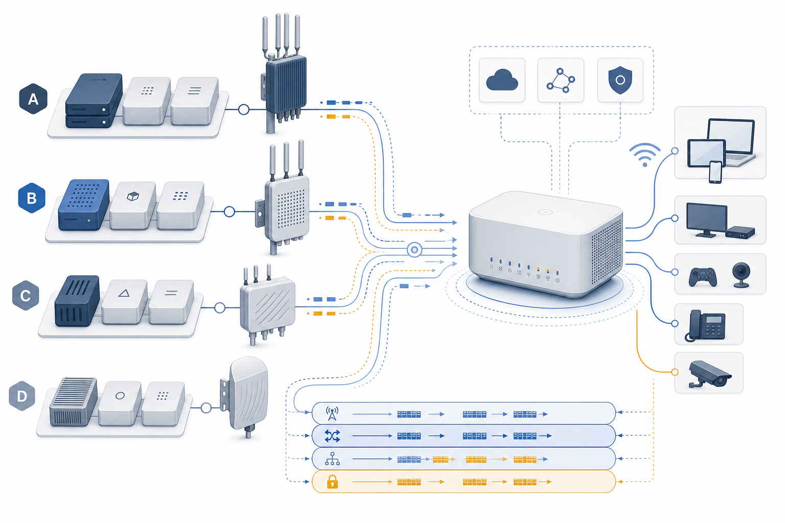
    At its core, carrier aggregation combines multiple frequency carriers—each an independent radio channel—into a single, wider logical data pipe. In 5G NR (New Radio), the aggregated bandwidth can span low-band (sub-1 GHz, e.g., n5, n28), mid-band (1–6 GHz, e.g., n77, n78, n79), and high-band/mmWave (24–47 GHz, e.g., n257, n258, n260, n261) spectrum simultaneously. A 5G CPE with robust CA capabilities can bond a 100 MHz n78 channel, a 40 MHz n5 channel, and a 400 MHz n260 mmWave carrier into a single 540 MHz effective bandwidth.

    This cross-band aggregation is what makes 5G FWA commercially viable at scale. The mid-band carrier provides the capacity layer for sustained high throughput, the low-band carrier provides the coverage layer for uplink reliability and indoor penetration, and the mmWave carrier—where available—provides the extreme-capacity layer for peak throughput. The CPE’s modem and antenna system must handle all three simultaneously, which is why CA configuration directly impacts bill of materials cost and thermal design complexity.

    CA Combinations: What Operators Should Specify in RFPs

    Not all CA combinations are created equal, and the combinations a CPE supports must match the operator’s spectrum holdings. The 3GPP specifications define hundreds of permitted CA combinations across FR1 (sub-7 GHz) and FR2 (mmWave), but practical CPE implementations support a meaningful subset. For operator procurement in 2026, the following CA configurations represent the minimum viable specification for carrier-grade FWA CPE:

    Essential FR1 CA combinations for mid-band FWA: n77+n77 (intra-band contiguous and non-contiguous) for markets with 80–100 MHz of C-band spectrum; n78+n78 for markets using the 3.3–3.8 GHz range; and n77+n5 or n78+n28 for mid-band plus low-band aggregation. These combinations ensure the CPE can aggregate the operator’s primary capacity band with supplementary low-band for uplink and coverage.

    FR1+FR2 (mmWave) CA: n77+n260 and n78+n257 combinations are critical for operators with mmWave holdings who want to deliver multi-gigabit peak speeds in dense urban and suburban deployments. The CPE modem must support EN-DC (E-UTRAN New Radio Dual Connectivity) for 4G anchor plus 5G data paths, as well as NR-CA within 5G standalone mode for future-proof SA architectures.

    Modem Selection: Qualcomm, MediaTek, and the CA Landscape

    The CPE’s modem chipset is the primary determinant of CA capability. In the current generation (2025–2026), the Qualcomm Snapdragon X75 and X80 modem-RF systems support up to 10 carrier aggregation across sub-7 GHz and mmWave, with 5× CA on sub-7 GHz alone. MediaTek’s T800 and forthcoming T830 platforms offer comparable CA density with slightly different band combination priorities—particularly strong in Asian and European band configurations where MediaTek’s market share is highest.

    For operators, the modem selection decision has cascading implications. Qualcomm-based CPE generally offers broader carrier certification coverage in North America and Europe. MediaTek-based CPE often delivers better price-performance ratios for price-sensitive markets in Southeast Asia, Africa, and Latin America. The key procurement question is not “which modem is better” but “which modem supports the CA combinations that match our deployed spectrum and target throughput.”

    Antenna Design: The Silent CA Enabler

    Carrier aggregation multiplies the antenna design challenge. Each aggregated band requires independent antenna paths with adequate isolation to prevent inter-band interference. A CPE supporting 3× CA across n77+n77+n5 needs at minimum 4×4 MIMO on n77 (four antenna elements) plus 2×2 MIMO on n5 (two elements)—a total of six independent antenna paths that must coexist within a compact enclosure while maintaining 15–20 dB of isolation between bands.

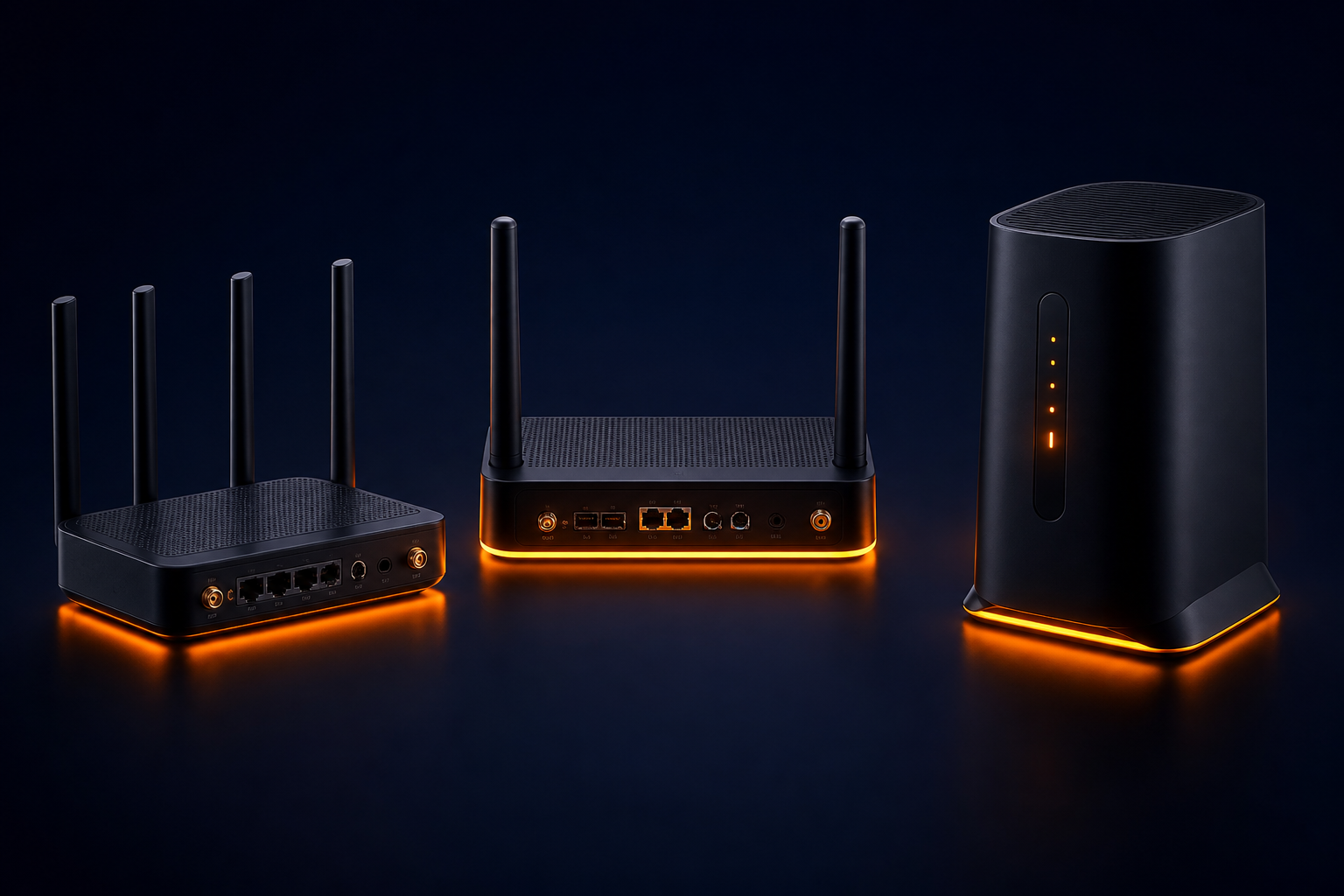
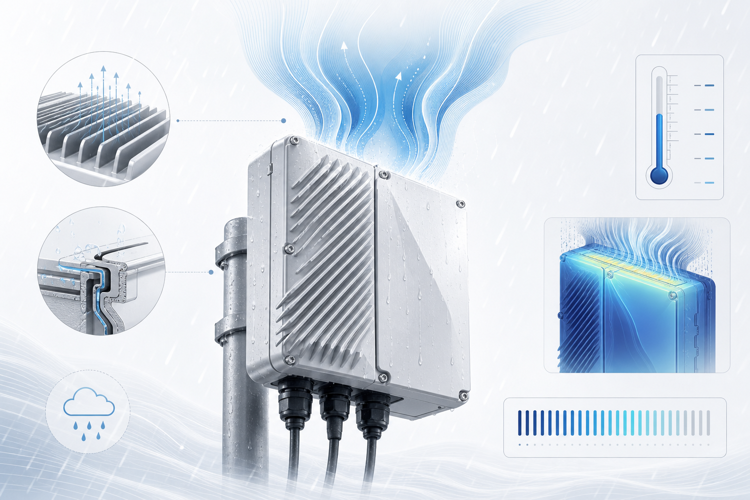
    This antenna density requirement is a key reason why outdoor CPE units consistently outperform indoor units in CA scenarios. The larger physical enclosure allows better antenna separation, while outdoor placement eliminates building penetration loss that disproportionately affects higher-frequency bands. When evaluating CPE for CA-heavy deployments, operators should strongly consider outdoor or window-mounted form factors for the primary FWA device.

    Procurement Checklist: CA Evaluation Criteria

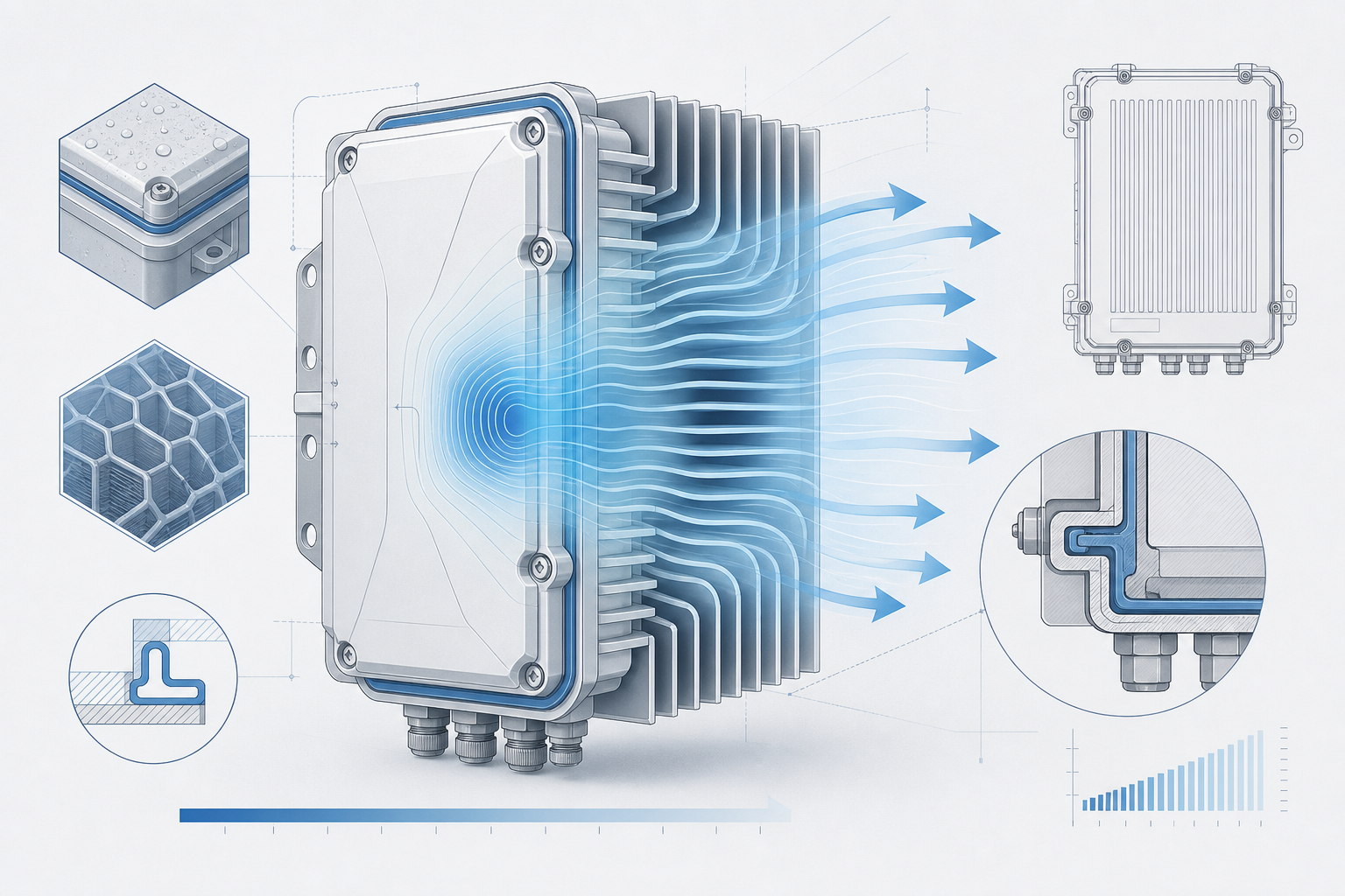
    When evaluating 5G CPE for carrier aggregation capability, operators should require vendors to provide: (1) a complete list of supported CA combinations as tested and certified, not just modem chipset theoretical capabilities; (2) throughput test results under controlled conditions for each supported CA configuration, including performance at cell edge (-115 to -120 dBm RSRP); (3) thermal performance data under sustained CA load—devices that throttle after 15–20 minutes of full CA throughput are not suitable for FWA use cases; and (4) carrier certification status for the operator’s specific network, including IOT (Interoperability Testing) completion reports.

    Carrier aggregation capability is not a binary yes/no specification—it is a multi-dimensional performance characteristic that directly determines the end-user experience, network efficiency, and service tier differentiation. Operators who invest the time to specify CA requirements precisely in their CPE RFPs will deploy FWA networks that deliver on their throughput promises, while those who treat CA as an afterthought will field a steady stream of “why is my internet slow” support tickets.

    Frequently Asked Questions

    Q: What is carrier aggregation in 5G and why does it matter for FWA CPE?

    Carrier aggregation (CA) combines multiple 5G frequency carriers into a single wider data pipe, dramatically increasing throughput. For FWA CPE, CA enables bonding low-band (coverage), mid-band (capacity), and mmWave (peak speed) simultaneously. A CPE with robust CA might deliver 1.5-3 Gbps where a non-CA device on the same network achieves 300-500 Mbps.

    Q: How many CA combinations should a carrier-grade 5G CPE support?

    A carrier-grade 5G FWA CPE should support at minimum: intra-band contiguous and non-contiguous CA on mid-band (n77+n77, n78+n78); mid-band plus low-band CA (n77+n5, n78+n28); and ideally FR1+FR2 CA (n77+n260, n78+n257) for operators with mmWave spectrum. The exact combinations must match the operator’s deployed spectrum holdings.

    Q: Does carrier aggregation affect CPE thermal design?

    Yes, significantly. Each additional aggregated carrier increases modem power consumption by 15-25%. A CPE running 3× CA with 4×4 MIMO can consume 8-12W, requiring active cooling solutions. Operators should require vendors to provide sustained throughput data (not just peak) and thermal throttling thresholds. Passive cooling is usually only adequate for 2× CA configurations.

    Q: Qualcomm vs MediaTek modems: which is better for carrier aggregation?

    Both offer comparable CA density in their 2025-2026 generation platforms. Qualcomm X75/X80 provides broader carrier certification in North America and Europe. MediaTek T800/T830 offers competitive CA at lower cost, particularly strong in Asian and European bands. The decision should be based on which modem supports the specific CA combinations that match your spectrum, not brand preference.

  • The Enterprise 4G MiFi Buyer’s Guide: Selecting Portable Broadband Solutions for Field Operations and Business Continuity

    The Enterprise 4G MiFi Buyer’s Guide: Selecting Portable Broadband Solutions for Field Operations and Business Continuity

    While 5G dominates industry headlines, 4G LTE MiFi devices remain the workhorse of enterprise mobile connectivity in 2026—and for good reason. With mature global coverage, predictable performance characteristics, aggressive price points, and a supply chain that has addressed component shortages, 4G MiFi solutions deliver reliable portable broadband that meets the needs of field service teams, emergency responders, temporary offices, and business continuity scenarios across virtually every market worldwide.

    This guide provides a structured evaluation framework for enterprise buyers—ISPs, system integrators, fleet managers, and IT procurement professionals—who need to select 4G MiFi devices at scale. Whether deploying 500 units for a utility company’s field technicians or sourcing portable hotspots for a nationwide retail chain’s backup connectivity, the criteria below will help make informed procurement decisions.

    1. Define the Deployment Profile First

    Before evaluating specific models, document operational requirements across five dimensions: (a) user count per device—typical MiFi devices support 10–32 concurrent connections, and undersizing creates helpdesk tickets; (b) daily data consumption per user—streaming, video conferencing, and large file transfers quickly exhaust consumer-grade data plans; (c) mobility pattern—stationary, pedestrian, or in-vehicle; (d) geographic coverage—urban, suburban, or rural, and across which carriers; and (e) environmental conditions—indoor office, outdoor field, or industrial.

    These five dimensions determine the essential hardware specifications: battery capacity, antenna configuration, ruggedization rating, and carrier aggregation capabilities. A field survey team mapping rural infrastructure has fundamentally different requirements than a pop-up retail kiosk in a shopping mall.

    2. Carrier Aggregation: The Single Most Important Radio Specification

    In the 4G world, carrier aggregation (CA) capability is the primary determinant of real-world throughput. Entry-level MiFi devices with no CA support (Cat 4, up to 150 Mbps theoretical) deliver 15–40 Mbps in real-world conditions—adequate for email and basic browsing but insufficient for video conferencing or cloud application access. Cat 6 devices (2× CA, up to 300 Mbps) represent the performance floor for enterprise deployment, delivering 30–80 Mbps in typical urban environments.

    For power users and primary connectivity scenarios, Cat 12 (3× CA, up to 600 Mbps) or Cat 16 (4× CA, up to 1 Gbps) devices provide the headroom needed for concurrent users, VPN tunnels, and real-time collaboration tools. The cost increment from Cat 6 to Cat 12 is typically 25–40% per unit—a premium that pays for itself in reduced user frustration within the first quarter of deployment.

    3. Battery and Power Architecture

    Battery specifications on datasheets are measured under idealized lab conditions. In the field, real-world battery life runs 50–70% of published figures. When evaluating devices, prioritize removable batteries for fleet deployments—the ability to hot-swap a depleted battery eliminates device downtime and simplifies lifecycle management. A 3000 mAh battery provides approximately 6–8 hours of active use in real-world conditions; for full-shift coverage (10–12 hours), look for 4000–5000 mAh or plan for swappable battery logistics.

    Also evaluate charging options beyond USB-C. Devices that support charging cradles with Ethernet pass-through enable fixed-location use cases (temporary office, event connectivity) where the MiFi doubles as a stationary CPE. Quick Charge 3.0 or USB-PD support reduces downtime between battery swaps.

    4. Management and Security: Non-Negotiable Enterprise Requirements

    Consumer-grade MiFi devices lack the management tooling that enterprise fleets require. At minimum, your selected device must support: (a) remote device management via TR-069 or TR-369 USP for configuration, firmware updates, and diagnostics; (b) VPN passthrough and ideally an onboard VPN client (IPsec/L2TP/WireGuard) for securing traffic at the device level; (c) customizable APN and PDP context settings for private APN and M2M SIM deployments; (d) FOTA (Firmware Over-The-Air) with scheduled update windows and rollback capability; and (e) RADIUS/Diameter AAA integration for operator-managed deployments.

    Security certifications matter. Look for devices with Wi-Fi Alliance WPA3 certification, FCC/CE compliance for target markets, and ideally PTCRB or GCF certification for carrier interoperability. For government and defense-sector deployments, FIPS 140-2 validated encryption modules may be required.

    5. Total Cost of Ownership: Beyond the Unit Price

    The per-unit hardware cost is only the starting point. A proper TCO model includes: device management platform licensing (typically $1–4 per device per year for cloud ACS); battery replacement cycles (plan for one replacement per device over a 3-year lifecycle); SIM and data plan costs (negotiate pooled data across devices rather than per-device plans); support and RMA overhead (enterprise-grade devices typically have 2–5% annual failure rates vs. 8–15% for consumer devices); and training and deployment logistics.

    When the full TCO is modeled over 36 months, the $30–50 premium for an enterprise-grade MiFi over a consumer hotspot is typically recovered within the first 6 months through reduced support tickets and lower failure rates alone. OEM/ODM partners who offer customized firmware, private labeling, and direct warranty support can further compress TCO for large-scale deployments.

    Frequently Asked Questions

    Q: What minimum 4G category (Cat) should an enterprise MiFi support?

    Cat 6 (2× carrier aggregation, up to 300 Mbps) is the minimum recommended for enterprise deployment. Cat 4 devices without CA are adequate only for light email and messaging. For teams using video conferencing, VPN, and cloud applications, Cat 12 (3× CA, up to 600 Mbps) is strongly recommended. The $30-50 premium over Cat 6 is recovered quickly through improved user productivity.

    Q: How many devices can connect to a 4G MiFi simultaneously?

    Enterprise-grade 4G MiFi devices typically support 16-32 concurrent Wi-Fi connections. However, the practical limit depends on usage patterns: 10-15 light users (email, messaging) or 5-8 heavy users (video conferencing, large file transfers). For larger groups, consider deploying multiple MiFi units or a fixed 4G CPE with higher Wi-Fi capacity.

    Q: Should I choose removable or sealed batteries for fleet deployment?

    Removable batteries are strongly recommended for fleet deployments. Hot-swappable batteries eliminate device downtime, simplify lifecycle replacement (batteries degrade after 300-500 charge cycles), and allow carrying spare batteries instead of spare devices. A charging cradle ecosystem with spare batteries reduces per-user logistics costs by approximately 30% over a 3-year lifecycle.

    Q: What management protocols should enterprise MiFi devices support?

    At minimum, enterprise MiFi devices should support TR-069 for remote management. For new deployments in 2026, TR-369 USP support is strongly recommended for future-proofing. The management platform should enable centralized configuration, scheduled firmware updates, real-time performance monitoring, and bulk operations across the device fleet.

  • TR-369 User Services Platform Gains Traction in 2026 Carrier CPE Deployments: The Transition Away from TR-069 for Next-Generation Device Management

    TR-369 User Services Platform Gains Traction in 2026 Carrier CPE Deployments: The Transition Away from TR-069 for Next-Generation Device Management

    The Broadband Forum’s TR-369 User Services Platform (USP) is experiencing its steepest adoption curve to date in 2026, as telecommunications operators across Europe, North America, and Asia-Pacific accelerate their migration away from the aging TR-069 (CWMP) protocol. With over 40 million USP-capable CPE devices now in active deployment globally, the industry is reaching a decisive inflection point in device management architecture.

    TR-069 served the broadband industry capably for nearly two decades, providing basic provisioning, firmware updates, and diagnostics for residential gateways. But as operator networks evolve toward virtualized, multi-service, and AI-driven operations, CWMP’s limitations—synchronous request-response architecture, limited security model, and inability to support complex IoT and multi-tenant scenarios—have become untenable at scale.

    What Makes TR-369 Fundamentally Different

    TR-369 USP represents a complete architectural redesign rather than an incremental upgrade. Built around a microservices-oriented, event-driven architecture, USP uses a message bus paradigm where devices, controllers, and applications communicate asynchronously through a common data model derived from TR-181 Device:2. This enables operators to push configuration changes simultaneously across thousands of devices, receive real-time telemetry without polling, and implement zero-touch provisioning at wire speed.

    Key technical advantages over TR-069 include: native TLS 1.3 encryption with mutual certificate-based authentication; MQTT and WebSocket transport protocols replacing unreliable HTTP sessions; multi-controller support allowing a single CPE to be managed by both the operator and enterprise IT simultaneously; and a subscription-notification mechanism that eliminates the bandwidth overhead of periodic CWMP Inform messages.

    Carrier Adoption Milestones in 2026

    Several Tier-1 operators have made public commitments to full USP migration in 2026. Deutsche Telekom has mandated USP support in all new CPE procurement tenders for its European subsidiaries. BT Group’s Openreach network now requires USP compliance for any FTTP CPE connecting to its wholesale fiber platform. In North America, three major cable MSOs have begun USP field trials for their next-generation DOCSIS 4.0 gateways, targeting production deployment by Q4 2026.

    For CPE manufacturers, this shift carries significant implications. Devices must now support the full USP 1.3 agent specification, including the Software Module Management (SMM) service for containerized application deployment and the IoT data model extensions standardized in TR-181. Carriers are increasingly evaluating CPE vendors not just on radio performance and price, but on the maturity of their USP implementation—including certification status from BBF.067 compliance testing.

    Market Implications for CPE Procurement

    Industry analysts project that USP-capable CPE will account for 65% of all new carrier gateway shipments by 2027. The immediate procurement impact is twofold: operators must dual-stack their ACS (Auto Configuration Server) environments to support both TR-069 and TR-369 during the multi-year transition, while CPE manufacturers face increased software development costs to implement, test, and certify USP agents across their product lines.

    For operators still in the RFP stage for 5G FWA and next-gen broadband CPE, USP compliance should be a mandatory line item in technical specifications. The protocol’s support for bulk provisioning, real-time performance monitoring, and multi-tenancy directly influences operational OPEX and customer experience KPIs. Waiting until 2027 to mandate USP risks deploying a fleet of devices that will require costly software upgrades or premature replacement within 18-24 months.

    The TR-369 ecosystem continues to mature rapidly. Open-source USP agent implementations are now available from prpl Foundation and RDK-B, reducing integration barriers. Commercial ACS/controller platforms from Axiros, Friendly Technologies, and Incognito have all released production-grade USP support. The industry consensus at Broadband World Forum 2025 was unambiguous: TR-069 is in its final chapter, and the operators moving fastest on USP adoption will gain measurable operational advantages in device lifecycle management, security posture, and service agility.

    Frequently Asked Questions

    Q: What is TR-369 USP and how does it differ from TR-069?

    TR-369 User Services Platform (USP) is the Broadband Forum’s next-generation device management protocol that replaces TR-069 (CWMP). Unlike TR-069’s synchronous HTTP-based request-response model, USP uses an asynchronous message bus architecture with MQTT/WebSocket transport, TLS 1.3 encryption, multi-controller support, and real-time telemetry subscriptions. It enables operators to manage devices more efficiently at scale and supports modern use cases like IoT, multi-tenancy, and containerized application deployment.

    Q: When should operators mandate USP support in CPE RFPs?

    Operators should include USP 1.3 compliance as a mandatory requirement in all new CPE procurement tenders starting in 2026. Major carriers including Deutsche Telekom and BT Group have already done so. Delaying USP requirements until 2027-2028 risks deploying devices that will require premature replacement or costly software upgrades within the typical 3-5 year CPE lifecycle.

    Q: Can USP and TR-069 coexist during the transition period?

    Yes. Operators typically dual-stack their ACS/controller environment to support both protocols simultaneously during the multi-year migration. Many CPE vendors now offer devices with both TR-069 and USP agents, allowing gradual fleet migration. The USP specification also defines a proxy mechanism for managing legacy TR-069 devices through a USP controller.

  • Open RAN Deployments Create New CPE Interoperability Requirements: What Telecom Buyers Need to Know in 2026

    Open RAN Deployments Create New CPE Interoperability Requirements: What Telecom Buyers Need to Know in 2026

    Open RAN Momentum Creates New CPE Interoperability Demands

    The global Open RAN market is projected to surpass $15 billion by 2027, driven by operator demand for multi-vendor radio access networks that break vendor lock-in. As this architectural shift accelerates, a critical question emerges for telecom buyers: how do CPE devices maintain seamless interoperability across heterogeneous Open RAN deployments?

    The Multi-Vendor Challenge for CPE

    Traditional RAN deployments pair a single vendor’s baseband unit (BBU), radio unit (RU), and core network — ensuring end-to-end compatibility testing. Open RAN disaggregates these components, allowing operators to mix RU from Vendor A with DU/CU from Vendor B and core from Vendor C. While this creates procurement flexibility, it introduces interoperability testing complexity at the CPE edge.

    For CPE devices, the challenge is clear: the device must reliably attach, authenticate, and maintain sessions across multi-vendor network configurations without requiring per-deployment firmware customization.

    Key Interoperability Requirements for Open RAN-Ready CPE

    1. O-RAN Alliance Compliance

    CPE devices targeting Open RAN deployments should support O-RAN Alliance fronthaul specifications (Split 7.2x) and demonstrate successful interoperability at O-RAN Global PlugFests. Third-party validation through organizations like TIP (Telecom Infra Project) provides additional assurance for operators.

    2. 3GPP Release 17/18 Feature Alignment

    Open RAN networks increasingly deploy Release 17 and 18 features — including NR-U (NR in unlicensed spectrum), multi-TRP (multiple transmission reception points), and enhanced carrier aggregation across non-co-located cells. CPE devices must support these features at both the modem and antenna system level to maintain peak performance in disaggregated architectures.

    3. Flexible Beam Management

    In Open RAN deployments, beamforming configurations may differ between vendors’ radio units even within the same network. CPE devices need robust beam acquisition and tracking algorithms that adapt to varying beam patterns, SSB periodicities, and CSI-RS configurations from different RU vendors.

    Industry Response: Certification Programs and Testbeds

    The industry is responding with dedicated testing frameworks. The O-RAN Alliance’s Open Testing and Integration Centers (OTIC) now include CPE interoperability test cases. Similarly, major operators including Vodafone, Deutsche Telekom, and Rakuten Mobile have published CPE acceptance criteria for their Open RAN networks, creating de facto industry standards for multi-vendor performance validation.

    What This Means for Telecom Buyers

    For ISPs, operators, and system integrators procuring CPE in 2026, Open RAN readiness should be a formal evaluation criterion in vendor RFPs. Key questions to ask CPE suppliers include:

    • Has the CPE been tested at an OTIC lab or O-RAN Global PlugFest?
    • Does the device support 3GPP Release 17 multi-TRP and enhanced CA across non-co-located cells?
    • What beam management fallback strategies are implemented for mixed-vendor RU environments?
    • Is a field-upgradeable firmware architecture in place to address future O-RAN specification updates?

    Conclusion

    Open RAN is transforming how mobile networks are built — and CPE procurement strategies must evolve accordingly. The operators that succeed in this new paradigm will be those who partner with CPE manufacturers that have invested in Open RAN interoperability testing, multi-vendor validation, and flexible firmware architectures designed for disaggregated network environments.

    Contact Honlly Telecom to discuss Open RAN-ready 4G/5G CPE solutions for your network — with O-RAN Alliance compliant designs and proven multi-vendor interoperability.

  • Thermal Design for Outdoor 5G CPE: Engineering IP67-Rated Enclosures for Extreme Climate Deployments

    Thermal Design for Outdoor 5G CPE: Engineering IP67-Rated Enclosures for Extreme Climate Deployments

    Introduction: Why Outdoor CPE Thermal Design Matters

    Outdoor 5G CPE devices face some of the harshest operating conditions in telecom infrastructure. Mounted on rooftops, poles, and building exteriors, these devices must maintain reliable performance across temperature extremes from -40°C desert nights to +55°C direct sunlight — all while dissipating heat from power-hungry 5G chipsets. Effective thermal management is not optional — it is the difference between a 5-year field life and a 6-month failure rate.

    This engineering guide examines the thermal design principles, materials, and testing protocols that ensure outdoor 5G CPE achieves IP67-rated protection while maintaining safe operating temperatures for internal components.

    Understanding the Thermal Challenge in 5G Outdoor CPE

    5G NR CPE devices generate significantly more heat than their 4G predecessors. The combination of multi-gigabit throughput, carrier aggregation across multiple bands, and beamforming antenna arrays pushes power consumption to 15–30W — comparable to a small laptop. In a sealed IP67 enclosure with no active fan, this heat has nowhere to go except through passive conduction and radiation.

    Key Heat Sources in Outdoor 5G CPE

    • 5G modem/baseband processor: 4–8W for sub-6 GHz; up to 12W for mmWave-capable chipsets
    • RF front-end and power amplifiers: 3–6W depending on TX power and number of antenna chains
    • WiFi 6/7 subsystem: 2–4W for dual-band concurrent operation
    • Ethernet PHY and PoE PD controller: 1–2W
    • Total thermal budget: 12–25W for typical outdoor 5G CPE

    IP67 Enclosure Requirements and Thermal Trade-offs

    IP67 certification requires complete protection against dust ingress (6) and immersion in 1 meter of water for 30 minutes (7). This means the enclosure must be hermetically sealed — no ventilation holes, no fans, no air exchange with the outside environment. Every watt of heat generated must be transferred through the enclosure walls via conduction.

    The fundamental trade-off: better sealing = worse natural cooling. Solving this requires careful material selection and enclosure geometry optimization.

    Passive Cooling Design Strategies

    1. Conductive Heat Path Optimization

    Direct thermal contact between high-power components and the enclosure body is the most efficient passive cooling method. Thermal interface materials (TIM) — typically silicone-based gap fillers with 3–6 W/mK conductivity — bridge the air gap between chip surfaces and the aluminum heatsink or enclosure wall. For 5G CPE, a 0.5–1.0 mm gap filler compressed to 30% provides optimal thermal transfer without stressing solder joints.

    2. Aluminum Die-Cast Enclosure with Integrated Fins

    Die-cast aluminum (ADC12 or A380 alloy) is the material of choice for outdoor CPE enclosures. Its thermal conductivity (96–130 W/mK) is 100× higher than plastic alternatives. External cooling fins increase surface area by 300–500%, dramatically improving convective heat transfer to ambient air. Modern designs use computational fluid dynamics (CFD) simulation to optimize fin spacing, height, and orientation for maximum natural convection at the target wind speeds for the deployment region.

    3. Phase-Change Materials for Peak Load Buffering

    For deployments in regions with extreme daily temperature swings, paraffin-based phase-change materials (PCMs) embedded in the enclosure wall can absorb heat during peak afternoon operation and release it during cooler evening hours. This thermal buffering smooths temperature peaks by 8–15°C, extending component lifespan without adding active cooling complexity.

    Testing and Validation: Beyond the Datasheet

    Real-world thermal validation goes far beyond component datasheet specifications. Reputable CPE manufacturers conduct:

    • Thermal chamber cycling: -40°C to +85°C, 500+ cycles, monitoring LTE/5G throughput stability
    • Solar load testing: 1,120 W/m² simulated solar radiation at 55°C ambient, 8-hour duration
    • Condensation testing: Rapid temperature transitions (85°C to -40°C in 15 seconds) to verify no internal moisture accumulation
    • Accelerated life testing: Continuous operation at 85°C component junction temperature for 1,000+ hours

    FAQ

    Q: Can outdoor CPE use active cooling (fans)?
    A: Not in IP67-rated enclosures. Active cooling requires air intake/exhaust, which breaks the dust and water seal. All cooling must be passive. Some industrial designs use sealed liquid cooling loops, but these add cost and complexity rarely justified for CPE.

    Q: How does solar radiation affect thermal performance?
    A: Direct sunlight adds 500–1,120 W/m² of radiative heat load to the enclosure surface. Light-colored (white or light gray) enclosures with high solar reflectance (>0.85) reduce solar absorption by 40–60% compared to dark-colored units.

    Q: What is the typical operating temperature range for outdoor 5G CPE?
    A: Industrial-grade designs achieve -40°C to +60°C ambient operation with full RF performance. Extended-temperature variants push to +70°C with graceful performance throttling above 55°C.

    Conclusion

    Thermal design is the silent differentiator between outdoor 5G CPE that survives a decade in the field and units that fail within the first summer. When evaluating CPE suppliers, buyers should request full thermal validation reports — not just spec sheets — and prioritize manufacturers with in-house environmental testing laboratories and proven field-deployment track records in target climate zones.

    Contact Honlly Telecom to discuss outdoor 5G CPE with validated IP67 thermal designs for your deployment region — backed by ISO 9001 manufacturing and full environmental test reports.

  • Untitled post 2945

    Introduction: The eSIM Revolution in Telecom CPE

    For telecom operators, ISPs, and MVNOs managing multi-country CPE deployments, the traditional plastic SIM card has long been a logistical bottleneck. Each device must be paired with a region-specific SIM, creating fragmented inventory, complex warehouse management, and delayed rollouts. eSIM (embedded SIM) technology with Remote SIM Provisioning (RSP) is changing this equation fundamentally. This article explores how eSIM integration in 4G and 5G CPE devices simplifies global operator deployment, reduces supply chain complexity, and enables new business models for telecom equipment buyers.

    What is eSIM RSP and Why It Matters for CPE

    Unlike traditional SIM cards that are physically inserted and locked to a single operator profile, eSIM RSP (GSMA SGP.22) allows operators to remotely download, activate, and switch carrier profiles over the air. For CPE devices — fixed wireless access routers, MiFi hotspots, and industrial gateways — this means:
    • Single SKU global inventory: One device model ships worldwide, with operator profiles provisioned at destination
    • Over-the-air operator switching: End users or enterprise IT can change carriers without physical SIM swaps
    • Reduced logistics costs: Eliminate per-country SIM kitting, warehousing, and regional packaging variants
    • Faster time-to-market: Deploy CPE in new markets in days, not months

    eSIM Architecture in CPE: Technical Considerations

    Integrating eSIM into CPE devices requires careful engineering across several layers:

    1. eUICC Hardware Integration

    The embedded Universal Integrated Circuit Card (eUICC) must meet GSMA SGP.02 compliance. For 5G CPE, the eUICC should support the M2M (Machine-to-Machine) profile with robust remote management capabilities. Industrial-grade eUICCs rated for -40°C to +105°C are recommended for outdoor CPE deployments.

    2. Local Profile Assistant (LPA) Implementation

    The LPA is the software component that communicates between the eUICC and the operator’s Subscription Manager Data Preparation (SM-DP+) server. For CPE devices running OpenWrt or Linux-based firmware, LPAs can be implemented as daemons that manage profile downloads, activation, and deletion automatically — without user interaction.

    3. Multi-Profile and Multi-IMSI Support

    Advanced eSIM implementations support multiple operator profiles stored simultaneously, enabling CPE devices to switch between carriers based on signal quality, cost, or contractual arrangements. Combined with multi-IMSI capabilities, a single CPE can serve subscribers across multiple MNOs and MVNOs.

    Supply Chain Transformation: From Regional to Global

    The introduction of eSIM fundamentally restructures the CPE supply chain: Before eSIM: OEM → regional SIM kitting → country-specific packaging → regional warehouse → operator → end user. Each region requires separate inventory, increasing working capital and lead times. After eSIM: OEM → global warehouse → ship anywhere → operator provisions via RSP → end user. One universal SKU covers all markets, reducing inventory by up to 70% and cutting deployment time from months to days.

    Operator Benefits: Why ISPs and MVNOs Should Prioritize eSIM CPE

    For telecom operators, eSIM-enabled CPE delivers measurable operational advantages:
    • Reduced churn: Lock-in effect through eSIM profile management; subscribers stay within operator ecosystem
    • Dynamic carrier partnerships: MVNOs can negotiate and switch wholesale agreements without touching physical devices
    • Enterprise private network deployments: Factory-floor CPE can be reconfigured remotely as network topologies change
    • Compliance and security: GSMA-certified eSIM provisioning provides end-to-end encryption and anti-cloning protection

    5G and Beyond: eSIM as a Competitive Differentiator

    As 5G Standalone networks proliferate and network slicing becomes commercialized, eSIM-capable CPE becomes a strategic asset. Operators can offer differentiated slice-based services — ultra-reliable low-latency for manufacturing, enhanced mobile broadband for offices, massive IoT for smart cities — all provisioned to eSIM CPE over the air.

    FAQ

    Q: Is eSIM more expensive than traditional SIM for CPE? A: The eUICC hardware cost is marginally higher (approximately $0.80-$1.50 per unit), but this is offset by eliminating physical SIM cards, regional kitting, and complex inventory management. Total cost of ownership typically decreases by 15–25% at scale. Q: Can eSIM CPE work with operators that don’t support RSP? A: Yes — eSIM CPE can fall back to traditional SIM operation via a physical SIM slot alongside the eSIM. This hybrid approach provides maximum compatibility during the transition period. Q: What certifications are required for eSIM CPE? A: GSMA SAS-UP certification for eUICC manufacturing, plus regional regulatory approvals (CE, FCC). Reputable OEM/ODM partners handle the full certification lifecycle.

    Conclusion

    eSIM RSP integration represents the next frontier in CPE supply chain optimization. For operators and ISPs deploying fixed wireless access at scale, the combination of global SKU simplification, over-the-air provisioning, and multi-profile flexibility makes eSIM-capable CPE a strategic procurement priority in 2026 and beyond. Contact Honlly Telecom to discuss eSIM-enabled 4G/5G CPE for your next deployment — with flexible OEM/ODM customization, GSMA-compliant integration, and global logistics support.
  • Private 5G (NPN) Deployments Accelerate in 2026: CPE Requirements for Enterprise Industrial Networks

    Private 5G (NPN) Deployments Accelerate in 2026: CPE Requirements for Enterprise Industrial Networks

    Private 5G — formally defined in 3GPP as Non-Public Network (NPN) — is moving from pilot projects to production deployments across manufacturing, logistics, mining, and utilities in 2026. According to industry analysts, the global private 5G market is projected to exceed USD 12 billion by 2027, driven by enterprises seeking deterministic wireless connectivity that Wi-Fi cannot deliver in demanding industrial environments.

    The 2026 Acceleration: What’s Driving It

    Three trends are converging in 2026 to accelerate NPN adoption:

    • Spectrum availability: Regulators in Germany (3.7\u20133.8 GHz), the UK (n77 band), Japan (4.6\u20134.9 GHz), and the US (CBRS 3.55\u20133.7 GHz) now offer dedicated enterprise spectrum, removing the dependency on mobile operator partnerships for private deployments.
    • Device ecosystem maturity: Qualcomm, MediaTek, and UNISOC now offer chipsets with native NPN support, meaning CPE vendors can deliver NPN-capable devices without expensive customization.
    • Industry 4.0 ROI cases: Early adopters in automotive manufacturing and logistics are reporting measurable outcomes — 30\u201350% reduction in production line reconfiguration time, sub-10 ms latency for AGV (Automated Guided Vehicle) control, and 99.999% reliability in harsh RF environments.

    What NPN Means for CPE Requirements

    Enterprise-grade NPN CPE must meet requirements that differ significantly from consumer or even standard carrier-grade devices:

    • Standalone NPN (SNPN) support: The CPE must operate on an isolated 5G core without connecting to a public network. This requires SNPN-capable firmware with support for Network Identifier (NID) and manual PLMN selection restricted to the enterprise designated network.
    • URLLC (Ultra-Reliable Low-Latency Communication): For industrial control applications, the CPE must support 3GPP Release 16/17 URLLC features including mini-slot scheduling, configured grant transmission, and PDCP duplication — delivering consistent sub-10 ms latency.
    • Time-Sensitive Networking (TSN) integration: In factory environments, 5G must interwork with existing IEEE 802.1 TSN Ethernet infrastructure. NPN CPE acting as a TSN bridge requires 5G-to-TSN translator functionality and support for IEEE 802.1AS timing synchronization.
    • Industrial protocol compatibility: The CPE Ethernet interface should support PROFINET, EtherCAT, and Modbus TCP pass-through without packet loss or timing jitter that industrial controllers would reject.
    • Ruggedized form factor: Unlike office CPE, industrial NPN devices operate on factory floors with vibration, dust, and temperature swings. DIN-rail mounting, IP40+ ingress protection, and extended temperature range (\u221220\u00b0C to +60\u00b0C) are baseline requirements.

    System Integrator Considerations

    For system integrators designing NPN solutions, CPE selection should prioritize three factors:

    1. Certified interoperability: The CPE must be tested against the specific 5G core (Ericsson, Nokia, Druid, or open-source platforms like free5GC) and RAN (small cell or distributed antenna system) chosen for the deployment. Interoperability gaps discovered during commissioning are expensive to fix.

    2. Centralized device management: NPN deployments often span multiple factory sites with hundreds of CPE units each. TR-369 USP or SNMP-based remote management, zero-touch provisioning, and firmware-over-the-air (FOTA) update capability are essential for ongoing operations.

    3. Security certification: Industrial NPNs carry higher security requirements than public networks. CPE should support SIM-based authentication (SUCI encryption), IPsec tunnel termination, and ideally, compliance with IEC 62443 for industrial control system security.

    Outlook

    As NPN spectrum becomes available in more markets and the CPE ecosystem matures, enterprises have a growing window of opportunity to deploy private 5G for use cases that Wi-Fi 6E/7 cannot reliably serve. The CPE — as the network edge device connecting machines, sensors, and controllers — will play a defining role in whether these deployments deliver on their performance and reliability promises.

    FAQ

    What is the difference between SNPN and PNI-NPN?

    SNPN (Standalone NPN) operates a completely independent 5G network with its own core and RAN, identified by a unique NID. PNI-NPN (Public Network Integrated NPN) is a private slice within a public operator network, identified by a CAG (Closed Access Group) ID. CPE for SNPN must support NID-based network selection, which is not required for PNI-NPN.

    Can existing 5G CPE be firmware-upgraded for NPN?

    Some existing 5G CPE with 3GPP Release 16+ chipsets can add SNPN support through firmware updates. However, URLLC and TSN features require hardware-level support in the modem — a firmware update alone cannot add them if the baseband was designed for Release 15 eMBB only.

    Planning a private 5G NPN deployment? Contact Honlly Telecom to discuss NPN-capable CPE requirements and explore our industrial-grade 5G device portfolio.

  • Thermal Design for Outdoor 5G CPE: Engineering IP67-Rated Enclosures for Extreme Environments

    Thermal Design for Outdoor 5G CPE: Engineering IP67-Rated Enclosures for Extreme Environments

    Outdoor 5G CPE units face a thermal paradox: the 5G modem and RF front-end generate significant heat during high-throughput operation, yet the IP67-rated enclosure that protects these components from rain, dust, and humidity also traps that heat inside. Solving this thermal management challenge is one of the hardest problems in outdoor CPE engineering — and one that directly determines field reliability and service life.

    Why Outdoor CPE Thermal Design Matters

    A 5G CPE operating in sub-6 GHz or mmWave bands can dissipate 8\u201315 W during sustained data transfer. In an enclosed plastic or aluminum housing under direct sunlight — where ambient temperatures can reach 55\u00b0C in Middle Eastern or South Asian deployments — internal junction temperatures can exceed 100\u00b0C if cooling is inadequate. At these temperatures, modem performance throttles, RF output power drops, and component lifespan degrades rapidly.

    For operators deploying thousands of outdoor CPE units across diverse climate zones, thermal failure is not a theoretical risk — it is a predictable source of support tickets, truck rolls, and customer churn. Engineering the thermal solution correctly at the design stage pays for itself many times over in reduced field failure rates.

    IP67 Requirements and the Sealed Enclosure Challenge

    IP67 certification requires the enclosure to withstand immersion in 1 meter of water for 30 minutes — meaning the housing must be completely sealed against liquid ingress. This eliminates the simplest cooling method: ventilation. With no airflow through the enclosure, all heat generated by the modem, RF power amplifiers, and power supply must be conducted through the enclosure walls to the external environment.

    The engineering challenge breaks into three parts:

    • Internal heat spreading: Moving heat from concentrated hot spots (SoC, PA) to the enclosure surface area.
    • Enclosure-to-air transfer: Maximizing the rate at which the enclosure surface dissipates heat to ambient air.
    • Solar load management: Minimizing solar radiation absorption that adds heat to the system.

    Passive Cooling Strategies That Work

    Thermal Interface Materials and Heat Spreading

    The most critical thermal path in an outdoor CPE is from the modem/SoC die to the enclosure wall. High-performance thermal gap pads or phase-change materials bridge the air gap between the chip package and an aluminum heat spreader plate. The spreader plate — typically 2\u20134 mm thick aluminum — distributes heat across a much larger area than the chip package alone, reducing thermal resistance by an order of magnitude.

    In well-designed units, the heat spreader is mechanically bonded to the rear enclosure wall using thermal adhesive or screw-mounted with thermal grease. This creates a direct conduction path from silicon to the outside world, bypassing the insulating air gap inside the enclosure.

    Enclosure Material Selection

    Aluminum alloy enclosures (typically ADC12 or AL6061) offer approximately 100\u2013200x the thermal conductivity of plastic (PC/ABS). For outdoor CPE targeting ambient temperatures above 45\u00b0C, an aluminum housing is often the difference between sustained gigabit throughput and thermal throttling within 30 minutes.

    Where plastic enclosures are preferred for cost or RF transparency reasons, manufacturers may embed aluminum inserts or use thermally conductive plastics with filler materials (graphite, ceramic, or boron nitride). These materials achieve 5\u201310 W/m\u00b7K — better than standard plastics (0.2 W/m\u00b7K) but still far below aluminum (150\u2013200 W/m\u00b7K).

    External Fin Design

    Adding fins to the exterior enclosure surface increases the surface area available for convective and radiative heat transfer. A finned aluminum enclosure can improve heat dissipation by 40\u201360% compared to a smooth surface of the same footprint, without compromising the IP67 seal — since the fins are part of the solid enclosure casting, not openings.

    Fin orientation matters in outdoor installations: vertical fins promote natural convection (hot air rises along the fin channels), while horizontal fins trap heat. The best outdoor CPE designs orient fins vertically regardless of mounting position.

    Solar Radiation: The Overlooked Heat Load

    An outdoor CPE installed on a rooftop or exterior wall in direct sunlight can absorb 600\u20131000 W/m\u00b2 of solar radiation. A unit with a 0.05 m\u00b2 surface area facing the sun adds 30\u201350 W of external heat load — several times the internal heat generation from the electronics.

    Mitigation strategies include:

    • High-reflectivity surface coating: White or light-colored enclosures with a solar reflectance index (SRI) above 80 reflect most solar energy. A white aluminum enclosure can operate 10\u201315\u00b0C cooler than a dark grey equivalent.
    • Sun shield design: A secondary shield mounted with an air gap above the main enclosure blocks direct radiation while allowing airflow in the gap.
    • Installation guidelines: Specifying north-facing mounting (in the northern hemisphere) or shaded locations in deployment documentation reduces solar exposure without hardware changes.

    Testing and Validation for Extreme Environments

    Responsible CPE vendors validate thermal performance through environmental stress testing:

    • Thermal chamber testing: Operating the CPE at 55\u00b0C ambient with maximum throughput load for 24+ hours, monitoring modem temperature and throughput stability.
    • Solar simulation: Exposing the CPE to calibrated solar spectrum lamps at 1000 W/m\u00b2 while measuring internal temperatures.
    • Thermal shock cycling: Rapid transitions between -20\u00b0C and +60\u00b0C to verify that thermal expansion/contraction does not compromise the IP67 seal or damage solder joints.
    • Field pilot testing: Deploying units in target climate zones (e.g., Gulf region summer, Nordic winter) for 3\u20136 month validation before volume shipment.

    Operators evaluating outdoor CPE should request thermal validation reports — not just IP rating certificates — as part of vendor qualification. A unit that passes IP67 in a lab at 25\u00b0C may fail in the field at 55\u00b0C if thermal management was an afterthought.

    FAQ

    Does passive cooling limit 5G throughput?

    A properly designed passive cooling system does not limit throughput under normal operating conditions. The thermal solution should be sized for worst-case ambient temperature and continuous maximum load. If thermal throttling occurs during sustained throughput, the cooling design is undersized for the deployment environment.

    Why not use active cooling with a fan?

    Fans create an opening in the enclosure, which breaks the IP67 seal. While fan-protected enclosures with IP55 ratings exist, they add a mechanical failure point (fan bearing), increase power consumption, and require filter maintenance. For carrier-grade outdoor CPE, passive cooling is strongly preferred for reliability.

    How do you verify thermal performance before buying?

    Ask the vendor for: (a) thermal simulation reports showing junction temperatures at maximum rated ambient, (b) environmental chamber test logs with throughput data, and (c) field trial results from deployments in climate zones similar to your own. A vendor that cannot provide these documents has not validated their thermal design.

    Deploying outdoor 5G CPE in challenging environments? Contact Honlly Telecom to discuss thermal performance data and explore our IP67-rated outdoor CPE portfolio engineered for extreme conditions.

  • eSIM Integration in 4G/5G CPE: Simplifying Global Operator Deployment and Logistics

    eSIM Integration in 4G/5G CPE: Simplifying Global Operator Deployment and Logistics

    For telecom operators and ISPs managing multi-country CPE deployments, SIM logistics have long been a cost bottleneck. Physical SIM cards require country-specific inventory, manual provisioning, and in-field replacement when roaming agreements change — each step multiplying operational overhead. eSIM technology, now maturing across 4G and 5G CPE platforms, changes this equation fundamentally.

    What eSIM Means for CPE Deployment

    An embedded SIM (eSIM) is a soldered, remotely programmable SIM chip compliant with GSMA’s Remote SIM Provisioning (RSP) specifications. Unlike a traditional plastic SIM that binds a device to one operator profile, an eSIM-enabled CPE can store multiple operator profiles and switch between them over the air — without a technician visit or hardware swap.

    For CPE devices deployed across borders, this capability removes the need to stock SKU variants per operator. One hardware SKU can serve deployments in Germany, Brazil, and Indonesia — the operator profile is loaded after the device arrives at its destination.

    Supply Chain Simplification: One SKU, Global Reach

    In a traditional physical SIM model, an operator or distributor must:

    • Forecast demand per country and per operator partner
    • Procure CPE units pre-loaded with country-specific SIM cards
    • Manage separate inventory pools for each market
    • Handle returns and re-flashing when forecasts miss

    With eSIM, the procurement team orders a single CPE variant. The device ships to any regional warehouse, and the correct operator profile is downloaded during first boot or at a staging facility. This collapses SKU count, reduces warehousing complexity, and cuts the cost of demand-forecast errors dramatically.

    Remote SIM Provisioning: How It Works

    GSMA’s RSP architecture defines two core components: the SM-DP+ (Subscription Manager Data Preparation) server, managed by the operator or a third-party RSP platform, and the eUICC (embedded UICC) inside the CPE. The provisioning flow is straightforward:

    1. Profile download: The CPE connects to any available network (including a bootstrap profile) and contacts the SM-DP+ server.
    2. Mutual authentication: The SM-DP+ verifies the eUICC certificate and the eUICC authenticates the server.
    3. Profile installation: The operator profile — containing IMSI, authentication keys, and network parameters — is encrypted and installed on the eUICC.
    4. Profile activation: The CPE switches to the new profile and attaches to the target operator’s network.

    This entire process can be triggered remotely, at scale, and without physical access to the device. For operators managing tens of thousands of CPE units across multiple markets, the operational savings are substantial.

    Multi-Operator Switching: Reducing Roaming Costs

    An eSIM-capable CPE can hold multiple operator profiles simultaneously (typically 5\u201310, depending on eUICC memory). Combined with intelligent profile switching logic, the CPE can:

    • Select the lowest-cost operator for data based on time-of-day or usage thresholds
    • Fail over to a second operator when the primary network degrades
    • Switch profiles based on geographic location (detected via network MCC/MNC)

    This multi-IMSI capability is especially valuable for IoT and enterprise CPE use cases where devices move between regions or require guaranteed uptime. It also gives operators flexibility to renegotiate roaming agreements without touching deployed hardware.

    Key Considerations for CPE Procurement

    When evaluating eSIM-capable 4G/5G CPE for operator deployment, procurement teams should verify:

    • GSMA SGP.02 / SGP.22 compliance: Ensure the eUICC supports the M2M (SGP.02) or consumer (SGP.22) RSP architecture appropriate for the deployment model.
    • Profile memory capacity: Confirm how many operator profiles the eUICC can store and whether profile deletion/replacement is supported OTA.
    • Bootstrap connectivity: Understand how the CPE gains initial network access to download its first operational profile — bootstrap IMSI, Wi-Fi provisioning, or local staging tool.
    • SM-DP+ integration: Verify that your chosen RSP platform or operator SM-DP+ is compatible with the CPE vendor’s eUICC implementation.
    • Regulatory compliance: Some markets restrict permanent roaming or require local IMSI registration. eSIM simplifies compliance by enabling local profile provisioning.

    The Logistics Advantage: Real-World Impact

    Consider a European MVNO expanding to three new markets in Southeast Asia. With physical SIMs, the roll-out requires three separate CPE shipments, three inventory pools, and on-site technicians for installation. With eSIM-capable CPE, a single shipment covers all three markets. Devices are activated remotely after customs clearance, and the operator can provision local profiles from a central NOC. Deployment time shrinks from months to days.

    For fixed wireless access (FWA) deployments at scale — where CPE installation is already a major cost driver — eliminating the SIM-handling step reduces truck rolls, simplifies installer training, and accelerates time-to-revenue.

    FAQ

    Does eSIM increase CPE hardware cost?

    The eUICC chip adds a marginal component cost — typically under USD 1 per unit at volume. This is offset many times over by supply chain simplification and reduced SIM logistics expense. Most CPE vendors now offer eSIM as a standard or optional feature with negligible price impact.

    Can eSIM CPE fall back to a physical SIM?

    Many eSIM-capable CPE designs include both an eUICC and a physical SIM slot (hybrid configuration). This gives operators flexibility: use eSIM for primary deployment and the physical SIM slot for local testing or emergency fallback.

    What happens if the provisioning server is unreachable?

    Once a profile is installed on the eUICC, the CPE operates independently of the SM-DP+. The provisioning server is needed only during initial profile download or profile updates. If the server is unreachable at first boot, the CPE typically retries or falls back to a pre-loaded bootstrap profile.

    Is eSIM secure for operator credentials?

    Yes. The GSMA Security Accreditation Scheme (SAS) certifies eUICC manufacturing sites and SM-DP+ platforms. Profile data is encrypted end-to-end using the eUICC unique private key, which never leaves the secure element. The security model is more robust than a removable physical SIM.

    Looking for eSIM-ready 4G/5G CPE for your operator deployment? Contact Honlly Telecom to discuss your requirements and explore our CPE portfolio with integrated eSIM support.