Category: Blog

Technical guides and best practices

  • A Technical Buyer’s Guide to Wi-Fi 7 Integration in 5G CPE: Multi-Link Operation, 320 MHz Channel Bonding, and 4K QAM for Next-Generation Fixed Wireless Access Gateways

    A Technical Buyer’s Guide to Wi-Fi 7 Integration in 5G CPE: Multi-Link Operation, 320 MHz Channel Bonding, and 4K QAM for Next-Generation Fixed Wireless Access Gateways

    Why Wi-Fi 7 Matters for 5G Fixed Wireless Access

    The intersection of 5G Fixed Wireless Access (FWA) and Wi-Fi 7 (IEEE 802.11be) represents one of the most significant architectural advancements in residential and enterprise broadband delivery. As 5G FWA services routinely deliver 500 Mbps to 2 Gbps at the WAN interface, the local-area wireless distribution must keep pace — and Wi-Fi 6/6E, while capable, cannot fully exploit the multi-gigabit potential that mmWave and carrier-aggregated Sub-6GHz FWA connections enable. For operators, ISPs, and enterprise buyers evaluating 5G CPE gateways in 2026, understanding Wi-Fi 7 integration is now a critical procurement competency.

    Multi-Link Operation (MLO): The Wi-Fi 7 Game-Changer

    Multi-Link Operation (MLO) is the defining innovation of Wi-Fi 7 and the feature most directly relevant to 5G CPE performance. MLO enables a single Wi-Fi 7 access point — embedded within the 5G CPE gateway — to simultaneously transmit and receive data across multiple frequency bands (2.4 GHz, 5 GHz, and 6 GHz) using multiple radio links aggregated into a single logical connection.

    For FWA deployments, MLO delivers three transformative benefits. First, throughput aggregation: by bonding a 5 GHz channel and a 6 GHz channel simultaneously, MLO can push aggregate throughput beyond 5 Gbps at the local network level, ensuring the Wi-Fi distribution never becomes the bottleneck for multi-gigabit 5G WAN connections. Second, latency reduction: MLO’s simultaneous transmit/receive capability across bands allows the CPE to select the least-congested link for latency-sensitive traffic in real time, reducing worst-case latency by 40–60% compared to single-link Wi-Fi 6 operation. Third, reliability enhancement: if one band experiences interference or congestion, MLO seamlessly shifts traffic to the alternate link without session interruption — critical for operator SLAs that guarantee 99.9% service availability.

    MLO can be implemented in two modes: STR (Simultaneous Transmit and Receive) and NSTR (Non-Simultaneous Transmit and Receive). For 5G CPE gateways, STR-mode MLO is strongly recommended, as it enables true full-duplex multi-band operation without the synchronization constraints of NSTR mode. Operators should verify that CPE vendors explicitly support STR-MLO with at least two simultaneous links (2× MLO) in their Wi-Fi 7 implementations.

    320 MHz Channel Bandwidth: Unlocking 6 GHz Capacity

    Wi-Fi 7 doubles the maximum channel bandwidth from 160 MHz (Wi-Fi 6E) to 320 MHz in the 6 GHz band, enabling single-channel throughput of up to 2.4 Gbps with a 2×2 MIMO configuration at 4K QAM modulation. For 5G CPE gateways serving multi-user households or small offices, this expanded channel capacity means multiple 4K video streams, cloud gaming sessions, and video conference calls can coexist without contention.

    The practical implications for CPE design are significant. Supporting 320 MHz channels requires wider RF front-end bandwidth, more sophisticated power amplifier linearization, and enhanced filtering to maintain signal integrity across the full 320 MHz passband. These requirements add approximately 15–25% to the Wi-Fi subsystem bill of materials compared to Wi-Fi 6E implementations — a cost that must be weighed against the tangible user experience improvements and competitive differentiation that 320 MHz support provides.

    In markets where the full 6 GHz band (5925–7125 MHz) is available for unlicensed use — including the United States, Canada, Brazil, South Korea, and Saudi Arabia — 320 MHz operation is fully viable. In regions with partial 6 GHz availability, such as the European Union (5925–6425 MHz only), Wi-Fi 7 CPE can still operate at 160 MHz in 6 GHz while leveraging MLO to aggregate with 5 GHz channels for enhanced throughput.

    4K QAM: 20% More Data in the Same Spectrum

    Wi-Fi 7 introduces 4096-QAM (4K QAM) modulation, an upgrade from the 1024-QAM used in Wi-Fi 6. This higher-order modulation scheme encodes 12 bits per symbol instead of 10, delivering a 20% throughput improvement under the same channel conditions. In practical terms, a 2×2 MIMO Wi-Fi 7 link operating at 160 MHz with 4K QAM achieves approximately 2.9 Gbps PHY rate, compared to 2.4 Gbps with 1024-QAM — a meaningful gain for 5G FWA gateways where every bit of spectral efficiency counts.

    However, 4K QAM requires higher signal-to-noise ratio (SNR) and lower error vector magnitude (EVM) than 1024-QAM, limiting its effective range to approximately 6–8 meters in typical indoor environments. For 5G CPE deployments, this means 4K QAM benefits are concentrated in same-room and adjacent-room scenarios — precisely where high-bandwidth applications like VR streaming, large file transfers, and local NAS backups occur. Operators should not expect 4K QAM to extend coverage range, but should view it as a capacity multiplier within the primary coverage zone.

    Multi-RU Puncturing and OFDMA Enhancements

    Wi-Fi 7 introduces Multi-Resource Unit (MRU) allocation and preamble puncturing, which together address one of Wi-Fi 6’s most persistent pain points: spectral inefficiency caused by narrowband interference. Under Wi-Fi 6, if a 20 MHz sub-channel within an 80 MHz or 160 MHz transmission experienced interference, the entire transmission bandwidth was forfeited. Wi-Fi 7’s preamble puncturing allows the CPE to dynamically “puncture” the interfered sub-channel and continue transmitting on the remaining clean spectrum, recovering up to 75% of throughput that would have been lost under Wi-Fi 6.

    For 5G FWA gateways deployed in dense urban or multi-dwelling environments where Wi-Fi interference from neighboring networks is endemic, this feature alone can improve real-world throughput by 20–35% compared to identically positioned Wi-Fi 6 CPE devices. Combined with MLO, MRU puncturing ensures that 5G FWA subscribers consistently experience the full benefit of their WAN connection speed regardless of local Wi-Fi congestion.

    CPE Architecture Considerations: SoC Selection and Thermal Design

    Integrating Wi-Fi 7 into 5G CPE requires careful system-on-chip (SoC) selection. The leading platforms in 2026 — including Qualcomm’s Networking Pro series (IPQ9574, IPQ9570), MediaTek’s Filogic 880/860, and Broadcom’s BCM6765/BCM4771 families — offer varying degrees of integration between the 5G modem and Wi-Fi 7 subsystem. For carrier-grade deployments, platforms that integrate the 5G modem, Wi-Fi 7 baseband, and network processor on a unified architecture offer significant advantages in power efficiency, thermal management, and software cohesion.

    Thermal design deserves particular attention. A Wi-Fi 7 tri-band (2.4 + 5 + 6 GHz) radio subsystem operating at maximum configuration (320 MHz, 4×4 MIMO, 4K QAM, MLO enabled) can dissipate 8–12 watts under sustained load — roughly double the thermal output of an equivalent Wi-Fi 6 implementation. When combined with a 5G Sub-6GHz modem (3–5W) or mmWave module (6–10W), total system power can reach 18–22W. Effective passive cooling design — including heatsink surface area optimization, thermal via placement, and enclosure ventilation — is essential to prevent thermal throttling and ensure sustained multi-gigabit performance.

    Procurement Recommendations for Operators

    When evaluating 5G CPE with Wi-Fi 7 for carrier-grade deployments, operators and enterprise buyers should prioritize the following technical specifications:

    • MLO support: Minimum STR-mode 2× MLO (5 GHz + 6 GHz simultaneous). 3× MLO (2.4 + 5 + 6 GHz) preferred for premium tier.
    • Channel bandwidth: 320 MHz support in 6 GHz band. Verify regional regulatory compliance.
    • Modulation: 4K QAM (MCS 12–13) with EVM ≤ -38 dB for reliable operation.
    • MIMO configuration: Minimum 2×2 on 6 GHz, 4×4 on 5 GHz for enterprise-grade deployments.
    • OFDMA/MU-MIMO: Support for up to 16 spatial streams and 37 RUs for efficient multi-user scheduling.
    • Security: WPA3-Enterprise with 192-bit CNSA suite, OWE (Opportunistic Wireless Encryption) for open networks.
    • QoS integration: DSCP-to-802.11be QoS mapping to preserve end-to-end traffic differentiation from 5G core to Wi-Fi client.
    • Thermal design: Validated sustained throughput at 45°C ambient without throttling.

    At Honlly Telecom, our Wi-Fi 7-enabled 5G CPE platforms are engineered from the ground up for carrier-grade FWA deployments. We offer fully customizable OEM/ODM solutions with integrated 5G modem + Wi-Fi 7 SoC architectures, field-proven thermal management, and comprehensive operator-specific firmware customization. Our engineering team works directly with your network planning and procurement teams to ensure every specification aligns with your deployment requirements.


    Contact Honlly Telecom to discuss your Wi-Fi 7 5G CPE gateway requirements. Reach us at gerard@xmhonlly.com or visit honllytelecom.com to explore our full OEM/ODM product portfolio.

  • A Technical Buyer’s Guide to 5G CPE Power over Ethernet (PoE) Architecture: IEEE 802.3bt Type 4 Integration, Remote Power Management, and Outdoor Installation Best Practices for Carrier-Grade FWA Deployments

    A Technical Buyer’s Guide to 5G CPE Power over Ethernet (PoE) Architecture: IEEE 802.3bt Type 4 Integration, Remote Power Management, and Outdoor Installation Best Practices for Carrier-Grade FWA Deployments

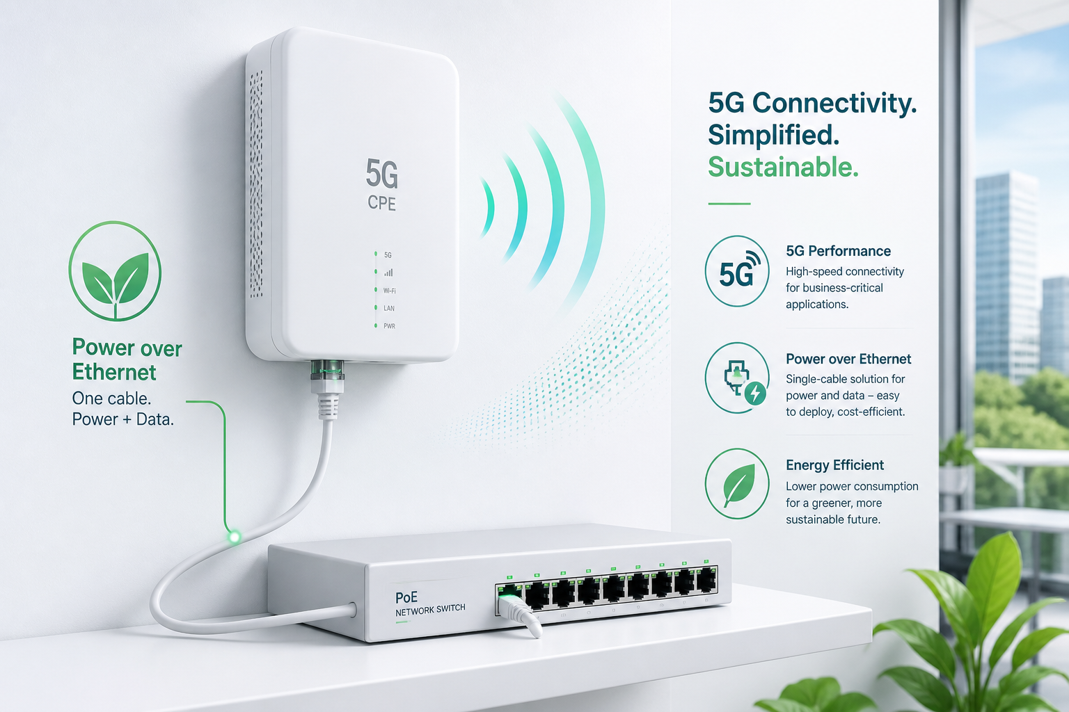
    Power over Ethernet (PoE) has evolved from a convenience feature for IP phones and cameras into a mission-critical infrastructure requirement for modern 5G Fixed Wireless Access CPE. As operators deploy outdoor and enterprise-grade CPE at scale — on rooftops, poles, building facades, and industrial sites — the ability to deliver both power and data over a single Ethernet cable dramatically reduces installation complexity, lowers total cost of ownership, and improves deployment flexibility. This guide examines the PoE architecture decisions that technical buyers must evaluate when selecting 5G CPE for large-scale FWA rollouts.

    IEEE 802.3bt Type 4: The New Baseline for 5G CPE

    The IEEE 802.3bt standard (PoE++ or 4PPoE), ratified in 2019, defines Type 3 (60W) and Type 4 (90W) power delivery over four-pair Cat6a/Cat7 cabling. For 5G CPE applications, Type 4 (90W at PSE, 71.3W guaranteed at PD over 100m) has emerged as the preferred specification for outdoor units powering high-gain antenna arrays, active beamforming modules, and multi-band RF front-ends that collectively draw 35–55W under full load.

    Key technical parameters that CPE procurement teams should verify:

    • PD Classification: The CPE should present Class 8 signature (802.3bt Type 4) during LLDP negotiation, ensuring the PSE delivers the full 90W budget. Devices misclassified as Class 4 (Type 2, 30W) will experience brownout under peak RF load.
    • Autoclass Support: Advanced CPE platforms implement Autoclass (802.3bt Annex A), which dynamically reports actual power consumption to the PSE every 30 seconds. This enables intelligent power budget management in multi-port PoE switches serving 8–24 CPE devices simultaneously.
    • Dual PD Redundancy: Carrier-grade outdoor CPE should support dual PoE inputs with automatic failover, ensuring uninterrupted operation if one PSE port or cable run fails. This is particularly critical for enterprise backhaul and public safety applications requiring five-nines availability.

    Cable Infrastructure: Cat6a Minimum, Cat7 Recommended

    Type 4 PoE at 90W pushes the thermal limits of Cat5e cabling, particularly in outdoor conduit installations exposed to direct sunlight. The DC resistance of 24AWG Cat5e (approximately 9.4Ω/100m per conductor) results in 5.8W of cable power loss at full 90W delivery, generating localized heating that accelerates insulation degradation and increases bit error rates on the data pairs.

    For outdoor 5G CPE installations, we recommend:

    • Minimum: Cat6a shielded (F/UTP or S/FTP), 23AWG solid copper, with outdoor-rated (CMX) jacket for exposed runs
    • Recommended: Cat7 S/FTP, 22AWG, with individually shielded pairs and overall braid — this provides 30% lower DC resistance than Cat6a and superior alien crosstalk rejection, which becomes significant when bundling multiple PoE cables in a single conduit riser
    • Maximum distance: 100 meters (328 feet) per 802.3bt specification, though operators deploying in high-temperature environments (ambient >40°C) should derate to 80 meters to maintain safe cable temperature margins

    Remote Power Management and Fleet Monitoring

    Enterprise and carrier CPE deployments benefit significantly from remote PoE management capabilities integrated into the device management platform. Modern 5G CPE supporting TR-369 USP (User Services Platform) can expose PoE telemetry — input voltage, current draw, PD class, and power negotiation logs — to centralized operations systems.

    Operational benefits of instrumented PoE telemetry include:

    • Predictive Maintenance: Gradual increase in current draw over weeks or months often precedes PSE or PD failure. Trend analysis across a fleet of thousands of CPE units enables proactive dispatch before service-impacting outages occur.
    • Power Budget Optimization: In dense multi-CPE installations (e.g., rooftop colocation sites), real-time per-port power monitoring prevents PSE oversubscription and enables dynamic load shedding during peak thermal conditions.
    • Installation Validation: Post-installation PoE diagnostics — cable resistance measurement, PD classification verification, and LLDP negotiation logs — provide automated quality assurance without requiring a truck roll for physical inspection.

    Surge Protection and Outdoor Hardening

    Outdoor PoE deployments introduce unique electrical safety considerations. A rooftop CPE connected via 100m Cat6a cable effectively creates a 100m antenna for induced lightning transients and ground potential differences between buildings. Technical buyers should verify that CPE devices include:

    • GDT-Based Primary Protection: Gas discharge tube surge arrestors rated for 6kV/3kA (IEC 61000-4-5 Class 4) on all four pairs at the PD input
    • Isolated PoE PD Interface: 1500VAC galvanic isolation between the PoE input and CPE logic ground, preventing ground loops in multi-building campus deployments
    • Outdoor Enclosure Rating: Minimum IP67 for the CPE enclosure with IP67-rated RJ45 connectors or hardwired cable gland terminations

    Procurement Checklist for PoE 5G CPE

    When evaluating 5G CPE with PoE for carrier-grade or enterprise deployments, technical buyers should verify the following minimum specifications:

    1. 802.3bt Type 4 (Class 8) PD compliance with 71.3W guaranteed available power
    2. Autoclass support with dynamic power reporting via LLDP
    3. Dual PD input with automatic failover (carrier-grade outdoor units)
    4. 1.5kVAC galvanic isolation between PoE input and system ground
    5. 6kV surge protection per IEC 61000-4-5 on all PoE pairs
    6. IP67 enclosure rating with outdoor-rated connector solutions
    7. TR-369 USP telemetry for remote PoE monitoring and fleet management
    8. Operating temperature range of -40°C to +65°C for outdoor deployments

    Honlly Telecom’s outdoor 5G FWA CPE series integrates 802.3bt Type 4 PoE with dual PD redundancy, comprehensive surge protection, and full TR-369 remote management — engineered for the real-world demands of carrier-scale outdoor FWA rollouts. Contact our engineering team to discuss PoE CPE specifications tailored to your deployment environment.

  • A Technical Buyer’s Guide to 5G CPE for Multi-Dwelling Units (MDUs): Distributed Antenna Systems, Indoor Coverage Optimization, Inter-Unit Interference Management, and Multi-Tenant FWA Deployment Architecture

    A Technical Buyer’s Guide to 5G CPE for Multi-Dwelling Units (MDUs): Distributed Antenna Systems, Indoor Coverage Optimization, Inter-Unit Interference Management, and Multi-Tenant FWA Deployment Architecture

    Multi-Dwelling Units (MDUs) — apartment buildings, condominiums, student housing, and mixed-use developments — represent one of the largest untapped addressable markets for 5G Fixed Wireless Access. Yet MDU deployments present unique RF propagation, interference management, and service demarcation challenges that differ fundamentally from single-family home installations. This guide provides technical buyers and operator planning teams with a structured framework for evaluating 5G CPE solutions purpose-built for multi-tenant environments.

    The MDU Signal Challenge: Building Penetration Loss

    Modern MDU construction materials impose significant RF attenuation that single-family CPE designs cannot reliably overcome. Low-emissivity (Low-E) coated windows — standard in energy-efficient buildings constructed after 2015 — attenuate mid-band 5G signals (3.5GHz n78) by 22–32dB, effectively reducing outdoor-to-indoor signal strength by 99.4–99.9%. Reinforced concrete floor slabs add 15–25dB per floor, while metal-framed curtain wall systems create unpredictable multipath and polarization distortion.

    For operators deploying FWA services to MDU residents, the critical metrics are:

    • Median RSRP at Window Position: Target ≥ -105 dBm for reliable 100Mbps+ service using 4×4 MIMO CPE with 6dBi integrated antennas
    • Building Entry Loss (BEL): Measured difference between outdoor RSRP and indoor RSRP at 1m from the window — BEL exceeding 15dB typically requires external antenna solutions
    • Floor-to-Floor Signal Variation: In buildings exceeding 6 stories, upper-floor units often experience 8–12dB stronger signals than ground-floor units due to reduced ground clutter and clearer line-of-sight to macro sites

    Distributed Antenna Architecture for MDUs

    For MDUs with high BEL or deep units where window-placed CPE cannot provide adequate whole-unit coverage, a distributed antenna system (DAS) architecture offers a scalable solution. In this configuration, an externally mounted donor antenna (typically a high-gain panel or log-periodic antenna on the rooftop or balcony) connects via low-loss coaxial cable to an indoor CPE unit placed centrally in the apartment.

    Key design parameters for MDU distributed antenna deployments:

    • Donor Antenna Gain: 8–11 dBi directional panel antenna with ±45° beamwidth, mounted with clear line-of-sight to the serving gNodeB sector
    • Cable Loss Budget: For cable runs up to 20m, LMR-400 equivalent (0.22 dB/m at 3.5GHz) limits total cable loss to 4.4dB — acceptable when paired with an 11dBi donor antenna yielding net 6.6dBi system gain. For runs exceeding 20m, 1/2-inch Heliax (0.13 dB/m) is recommended
    • CPE Antenna Port Configuration: The indoor CPE unit must support external antenna ports (SMA or TS-9 connectors) with automatic detection and switching between internal and external antenna paths

    Inter-Unit Interference Management

    In high-density MDU deployments where 20–50 units per floor may each operate a 5G CPE with integrated Wi-Fi 6/6E access point, co-channel and adjacent-channel interference becomes a significant performance degrader. Technical buyers should evaluate CPE platforms that incorporate:

    • Automatic Channel Selection (ACS): Wi-Fi radio management that continuously scans the 2.4GHz, 5GHz, and 6GHz bands and selects the least-congested channel based on both Wi-Fi and non-Wi-Fi interference sources
    • Transmit Power Control (TPC): Dynamic adjustment of Wi-Fi TX power based on apartment size — a studio apartment requires significantly less power than a three-bedroom unit, and excessive power only increases neighbor interference
    • DFS Channel Utilization: Aggressive use of DFS (Dynamic Frequency Selection) channels in the 5GHz band (channels 52–144), which tend to be underutilized in MDU environments due to consumer router default configurations avoiding them
    • 5G NR Interference Coordination: CPE supporting 5G NR-U (NR in unlicensed spectrum) or NR-based sidelink can coordinate with neighboring CPE units to avoid mutual interference on the 5G access link itself

    Multi-Tenant Service Demarcation and Management

    MDU deployments require clear service demarcation between the operator’s responsibility (the CPE and its WAN connection) and the resident’s domain (the LAN/Wi-Fi network). Enterprise-grade CPE platforms address this through:

    • Dual-SSID Architecture: A carrier-managed SSID (for performance monitoring, firmware updates, and QoS enforcement) alongside a resident-managed SSID with self-service portal for password changes and parental controls
    • Per-Tenant VLAN Tagging: 802.1Q VLAN isolation between units sharing common building infrastructure such as rooftop antenna systems or basement PoE switch aggregation, ensuring traffic separation and security between tenants
    • Bulk Provisioning API: TR-369 USP or TR-069 CWMP support for zero-touch provisioning of hundreds of CPE units simultaneously, with pre-configured tenant profiles mapping to building, floor, and unit identifiers

    Procurement Recommendations for MDU-Scale Deployments

    Technical buyers procuring 5G CPE for MDU deployments should prioritize the following specifications:

    1. External Antenna Support: SMA or TS-9 ports for optional external donor antenna connection, with automatic internal/external antenna path switching
    2. Wi-Fi 6E or Wi-Fi 7: 6GHz band support dramatically reduces intra-MDU interference by accessing 1200MHz of new, uncongested spectrum not available in 2.4/5GHz-only devices
    3. Per-Unit Power Budget ≤ 15W: Minimizes heat generation in enclosed spaces and enables PoE-powered operation from a centralized building switch
    4. TR-369 USP with Bulk Provisioning: Essential for operators deploying CPE at scale across hundreds to thousands of MDU units
    5. Multi-Language Self-Service Portal: Critical for MDUs serving international residents who may not be fluent in the operator’s primary language

    Honlly Telecom’s 5G FWA CPE portfolio includes MDU-optimized configurations with external antenna support, Wi-Fi 6E/7 integrated radios with advanced interference management, and TR-369 USP-based fleet orchestration — purpose-built for the unique demands of multi-tenant fixed wireless deployments. Contact our solutions engineering team to discuss MDU CPE configurations matched to your building typology and subscriber density requirements.

  • A Technical Buyer’s Guide to 5G CPE for Industrial IoT Environments: Protocol Bridging, Edge Computing Integration, and Ruggedized Design for Smart Factory Deployments

    A Technical Buyer’s Guide to 5G CPE for Industrial IoT Environments: Protocol Bridging, Edge Computing Integration, and Ruggedized Design for Smart Factory Deployments

    Industrial environments present a fundamentally different set of requirements for 5G CPE than enterprise branch offices or residential FWA deployments. The convergence of operational technology (OT) networks — built on deterministic, often decades-old industrial protocols — with information technology (IT) networks leveraging 5G connectivity demands a specialized class of CPE that bridges these two worlds while surviving the physical rigors of factory floors, process plants, and logistics centers. This guide examines the architectural and procurement considerations unique to industrial 5G CPE.

    Industrial Protocol Translation: Bridging OT and IT

    The defining capability of an industrial 5G CPE is its ability to translate between the protocols native to factory automation systems and the IP-based protocols of enterprise and cloud infrastructure. A facility may contain PLCs communicating via Modbus RTU over RS-485 serial links, drives and actuators controlled through PROFINET or EtherCAT, SCADA systems using OPC-UA, and legacy equipment speaking proprietary vendor protocols — all of which must be integrated into a unified 5G-connected architecture.

    A properly architected industrial CPE embeds a multi-protocol gateway engine capable of concurrent translation across these interfaces. The CPE should support Modbus TCP/RTU master and slave modes, enabling it to poll field devices and expose their register maps to cloud applications via MQTT Sparkplug B, the emerging standard for industrial IoT messaging. PROFINET and EtherNet/IP device integration allows the CPE to participate in real-time industrial Ethernet networks, subscribing to cyclic I/O data from automation controllers while simultaneously publishing selected data points to AWS IoT Core, Azure IoT Hub, or on-premises IIoT platforms. OPC-UA client/server functionality is essential for integration with modern SCADA and MES systems, with support for OPC-UA PubSub over MQTT enabling efficient data distribution without the polling overhead of traditional client-server architectures.

    Procurement teams should pay close attention to the protocol translation latency specification — the time from a field device value change to its availability as an MQTT message. For most monitoring and analytics use cases, sub-100ms translation latency is acceptable. For closed-loop control applications where the CPE participates in the control path, sub-10ms is required, necessitating real-time operating system (RTOS) or Linux with PREEMPT_RT kernel patches on the CPE’s application processor.

    Edge Computing Co-Processing: Intelligence at the Network Edge

    The industrial CPE’s role extends beyond connectivity into computation. Modern industrial 5G CPE platforms incorporate dedicated edge computing resources — typically Arm Cortex-A series application processors with 4–8 GB of RAM and 32–64 GB of eMMC or NVMe storage — that enable on-device data processing, analytics, and control logic execution without round-tripping data to the cloud. This edge computing capability is critical for latency-sensitive applications (sub-10ms control loops), bandwidth-constrained scenarios (processing high-frequency vibration data locally and transmitting only anomaly events), and air-gapped resilience (maintaining local control when WAN connectivity is interrupted).

    Containerization through Docker or containerd is the dominant edge application deployment model, allowing IT teams to package and deploy analytics microservices, protocol adapters, and local dashboard applications consistently across fleets of industrial CPE devices. Leading platforms support Kubernetes-based orchestration at the edge through lightweight distributions like K3s or MicroK8s, enabling the same DevOps workflows used in cloud environments to extend to the factory floor. When evaluating CPE edge compute capabilities, procurement teams should verify available CPU headroom after subtracting connectivity stack overhead, GPU/NPU availability for on-device machine learning inference (increasingly important for visual inspection and predictive maintenance applications), and hardware-backed security features including ARM TrustZone or equivalent TEE (Trusted Execution Environment) support for isolating critical industrial control workloads from general-purpose edge applications.

    Ruggedized Design: Surviving the Factory Floor

    Physical environmental resilience separates industrial CPE from commercial-grade devices. The minimum standard for industrial deployments is IP30 ingress protection for indoor factory environments, with IP65 or IP67 required for outdoor installations, washdown areas, or locations exposed to dust, moisture, or chemical splashes. The relevant IEC 60529 testing certification should be provided by the manufacturer, not merely claimed in marketing materials.

    Operating temperature range is equally critical. Industrial CPE should support at minimum -20°C to +60°C operation, with -40°C to +70°C required for outdoor installations in extreme climates or for deployment adjacent to process equipment generating substantial radiant heat. Extended temperature operation demands careful thermal design — passive conduction cooling via the enclosure and mounting surface is preferred over active fan cooling, which introduces a single point of failure and requires periodic maintenance incompatible with the 5–10 year lifecycle expectations of industrial infrastructure.

    Mounting and form factor should align with industrial installation practices. DIN-rail mounting (EN 60715 TH35) is the standard for control cabinet installations, while wall-mount and VESA-mount options address open-facility deployments. The CPE should accept DC input power (typically 12–48 VDC) from industrial power supplies, with dual redundant power inputs, reverse polarity protection, and surge protection compliant with IEC 61000-4-5 Level 3 or higher. Terminal block connectors for power, serial interfaces, and digital I/O should be accessible without removing the CPE from its mounting rail, enabling field wiring without service interruption.

    Electromagnetic Compatibility and Industrial Certifications

    Industrial environments are electromagnetically hostile — variable frequency drives, arc welding equipment, and high-power switching systems generate conducted and radiated emissions that can disrupt consumer-grade electronics. Industrial 5G CPE must demonstrate compliance with IEC 61000-6-2 (immunity for industrial environments) and IEC 61000-6-4 (emission standard for industrial environments), with test reports covering electrostatic discharge (ESD) to ±8kV contact / ±15kV air, radiated RF immunity to 10 V/m across 80 MHz–6 GHz, and electrical fast transient/burst immunity on power and signal ports.

    Beyond EMC, deployment in specific industrial verticals may require additional certifications. ATEX/IECEx Zone 2 certification is mandatory for CPE deployed in areas where flammable gases or vapors may be present (oil and gas, chemical processing, paint shops). EN 50155 compliance is required for railway applications, covering extended temperature, humidity, shock, and vibration requirements specific to rolling stock environments. DNV GL or equivalent marine certifications apply to offshore and maritime deployments. Procurement teams should map certification requirements to the target deployment environment early in the selection process, as certifications can add 6–12 months to product availability timelines if not already in place.

    Network Architecture: Segmentation, Security, and Determinism

    The industrial CPE must implement network segmentation that isolates OT traffic from IT traffic, even when both traverse the same 5G uplink. IEEE 802.1Q VLAN trunking with per-VLAN QoS policies enables the CPE to present separate logical interfaces for process control networks (PCN), supervisory networks, and enterprise IT networks, each with independently configurable security policies and bandwidth allocations. Industrial firewall functionality with stateful packet inspection and application-layer filtering for industrial protocols (Modbus deep packet inspection, DNP3 filtering) provides defense-in-depth between network segments without requiring a separate security appliance.

    Time-Sensitive Networking (TSN) over 5G is an emerging capability that extends deterministic Ethernet into the 5G domain. The 3GPP Release 17/18 TSN integration framework enables the 5G system to appear as a TSN bridge, preserving IEEE 802.1AS time synchronization and 802.1Qbv scheduled traffic capabilities across the wireless link. For motion control and other hard real-time applications requiring sub-millisecond jitter, TSN over 5G with integrated 5G-TSN translators in the CPE represents the cutting edge of industrial wireless, though commercial availability remains limited to early-adopter platforms in H2 2026.

    Fleet Management at Industrial Scale

    Industrial deployments rarely involve individual devices — a single smart factory retrofit may involve 50–200 CPE units, and a multi-site program can scale to thousands. The CPE management plane must support zero-touch provisioning (ZTP) through TR-369 USP (User Services Platform) or NETCONF/YANG, enabling devices to auto-configure upon first power-up by contacting a management server, downloading their site-specific configuration, and entering service without on-site technical intervention. Bulk configuration templates, staged firmware rollouts with automatic rollback on failure detection, and centralized certificate lifecycle management are operational necessities, not optional features, at industrial deployment scale.

    Integration with existing industrial asset management and SCADA systems is increasingly expected. CPE platforms that expose operational data — CPU load, memory utilization, interface statistics, cellular signal quality (RSRP, RSRQ, SINR per component carrier) — via OPC-UA or MQTT enable operations teams to monitor CPE health within the same dashboards used for PLCs, drives, and sensors, avoiding the operational friction of separate IT and OT monitoring silos.

    Honlly Telecom’s industrial 5G CPE portfolio delivers ruggedized DIN-rail devices with multi-protocol gateways, edge computing co-processors, extended temperature ratings, and comprehensive industrial certifications. Contact our B2B team to discuss your smart factory connectivity requirements.

  • A Technical Buyer’s Guide to 5G CPE QoS Architecture: Application-Aware Traffic Shaping, DSCP Marking, and End-to-End Latency Management for Carrier-Grade FWA Services

    A Technical Buyer’s Guide to 5G CPE QoS Architecture: Application-Aware Traffic Shaping, DSCP Marking, and End-to-End Latency Management for Carrier-Grade FWA Services

    Quality of Service (QoS) is the architectural backbone that distinguishes carrier-grade 5G FWA CPE from consumer-grade devices. While raw throughput dominates marketing specifications, the ability to classify, prioritize, shape, and guarantee service levels across diverse application workloads is what determines whether a 5G FWA deployment meets enterprise service-level agreements (SLAs) for voice, video, real-time control, and bulk data applications simultaneously. This guide examines the QoS subsystems that procurement teams should evaluate when selecting 5G CPE for multi-tenant, multi-service FWA deployments.

    Traffic Classification: The Foundation of QoS

    Effective QoS begins with accurate traffic classification. Modern 5G CPE platforms employ a multi-layer classification engine that operates at several inspection depths. Layer 2–3 classification uses 802.1p priority bits, VLAN IDs, IP source/destination addresses, and DSCP (Differentiated Services Code Point) markings inherited from upstream networks or application servers. This shallow-packet approach is computationally efficient and suitable for high-throughput scenarios but cannot distinguish between applications sharing the same IP endpoints.

    Deep Packet Inspection (DPI) extends classification to Layer 7, identifying over 3,500 application signatures including videoconferencing platforms (Zoom, Teams, Webex), VoIP protocols (SIP, RTP), business applications (Office 365, Salesforce, SAP), streaming services, and cloud storage sync traffic. Enterprise-grade CPE SoCs from Qualcomm (Networking Pro series) and MediaTek (T830/T750) include hardware-accelerated DPI engines capable of maintaining application identification at multi-gigabit throughput rates without imposing significant CPU overhead. Procurement teams should verify that the CPE’s DPI signature database receives regular updates — ideally weekly — to maintain classification accuracy as applications evolve and new services emerge.

    AI/ML-assisted classification is emerging as a differentiating feature in premium CPE platforms. These systems use machine learning models trained on traffic pattern characteristics — packet inter-arrival times, flow duration, burstiness profiles, and payload entropy — to classify encrypted traffic that resists signature-based DPI. While still maturing, ML-based classifiers have demonstrated over 92% accuracy in identifying encrypted video conferencing and VoIP traffic, applications where misclassification directly impacts perceived call quality.

    DSCP Marking and DiffServ Integration

    The DiffServ architecture, defined in RFC 2474/2475, provides the standardized marking framework that enables end-to-end QoS across heterogeneous network domains. In 5G FWA deployments, the CPE serves as the critical trust boundary where IP packets entering the 5G access network are classified and marked with appropriate DSCP values. The 3GPP 5G QoS model maps these IP-layer markings to 5G QoS Identifiers (5QIs), creating a consistent QoS chain from the application through the CPE, across the 5G RAN and core network, and into the IP transport domain.

    The standard 3GPP 5QI-to-DSCP mapping assigns 5QI 1 (GBR, conversational voice) to DSCP EF (46), 5QI 2 (GBR, conversational video) to DSCP AF41 (34), and 5QI 6–9 (non-GBR, various buffered streaming and TCP-based services) to DSCP AF11–AF33 (10–30). However, enterprise deployments often require custom mapping tables to align with internal QoS policies or MPLS DiffServ domains. CPE platforms should support configurable DSCP remarking policies that can overwrite, preserve, or conditionally modify markings at the trust boundary, with the ability to define separate policies for upstream (CPE-to-network) and downstream (network-to-CPE) directions.

    Hierarchical Queuing and Scheduling

    The queuing subsystem determines how classified traffic competes for egress bandwidth on the 5G WAN interface. Hierarchical Token Bucket (HTB) is the predominant scheduling architecture in enterprise CPE, enabling multi-level bandwidth allocation that mirrors organizational or service hierarchies. A typical enterprise HTB tree allocates a root rate matching the provisioned 5G link speed, with child classes for real-time services (guaranteed rate, strict priority), business-critical applications (guaranteed rate with borrowing capability), best-effort traffic, and network control protocols.

    The queuing discipline (qdisc) selection significantly impacts latency performance. Strict Priority Queuing (SPQ) ensures that real-time traffic is always serviced before other queues, minimizing jitter for voice and video but risking starvation of lower-priority classes during congestion. Weighted Fair Queuing (WFQ) provides proportional bandwidth allocation, preventing starvation while still enabling priority differentiation. Advanced CPE platforms implement hybrid SPQ+WFQ schemes where a small number of strict-priority queues handle ultra-low-latency traffic, with remaining bandwidth fairly distributed among non-real-time classes.

    For latency-sensitive enterprise applications, Active Queue Management (AQM) algorithms — particularly CoDel (Controlled Delay) and PIE (Proportional Integral controller Enhanced) — prevent bufferbloat by intelligently dropping or marking packets before queues reach problematic depths. RFC 8290 CoDel, operating on queue sojourn time rather than queue depth, has demonstrated the ability to maintain median latency below 5ms even under sustained full-load conditions on 5G FWA links, a critical capability for real-time collaboration and industrial control applications.

    Buffer Management and Congestion Avoidance

    Buffer architecture is often overlooked in CPE procurement yet has an outsized impact on real-world performance. The bufferbloat phenomenon — where excessively large buffers introduce hundreds of milliseconds of latency under load — is particularly problematic on 5G FWA links where TCP congestion control interacts with highly variable wireless link rates. Modern CPE designs should implement per-queue buffer limits rather than a single shared buffer pool, preventing a single greedy flow from consuming all buffer resources and inducing head-of-line blocking across all traffic classes.

    Explicit Congestion Notification (ECN), defined in RFC 3168, provides a more sophisticated alternative to tail-drop congestion management. ECN-capable CPE marks IP packets experiencing congestion rather than dropping them, allowing TCP senders to reduce their congestion window before packet loss occurs. This proactive approach maintains higher throughput while avoiding the TCP retransmission storms that characterize tail-drop congestion events. Procurement teams should verify that CPE platforms support ECN marking on both the 5G WAN and LAN interfaces, and that the configuration permits ECN to be enabled selectively per traffic class to avoid interactions with legacy endpoints that do not support ECN.

    End-to-End SLA Verification

    Beyond the architectural capabilities, the practical test of QoS effectiveness lies in measurable performance under realistic multi-service load conditions. Enterprise procurement teams should request RFC 2544 and Y.1564 test results demonstrating throughput, latency, jitter, and frame loss under concurrent voice (64 kbps G.711 streams), video (2–4 Mbps HD streams), and data (TCP bulk transfer) workloads that represent the target deployment profile. Key metrics to evaluate include one-way delay under 150ms for voice (ITU-T G.114 recommendation), jitter under 30ms without dejitter buffer compensation, and less than 0.1% packet loss for real-time services even when the link is saturated with best-effort traffic.

    Advanced CPE platforms incorporate TWAMP (Two-Way Active Measurement Protocol) reflectors that enable operators and enterprise IT teams to continuously monitor QoS performance from any TWAMP sender across the network. Combined with streaming telemetry that exports per-queue statistics (packets, drops, latency percentiles) via gRPC or NETCONF, these measurement capabilities close the loop between QoS policy configuration and verified service delivery, providing the visibility necessary to maintain SLA compliance at scale.

    Honlly Telecom’s 5G FWA CPE portfolio incorporates carrier-grade QoS subsystems with hardware-accelerated DPI, configurable DSCP remarking, hierarchical queuing, and AQM-based buffer management. Contact our technical sales team to discuss QoS requirements for your FWA deployment.

  • A Technical Buyer’s Guide to 5G CPE Thermal Management: Passive Cooling, Heat Dissipation Design, and Outdoor Enclosure Ratings for Sustained Multi-Gigabit Performance

    A Technical Buyer’s Guide to 5G CPE Thermal Management: Passive Cooling, Heat Dissipation Design, and Outdoor Enclosure Ratings for Sustained Multi-Gigabit Performance

    As 5G CPE devices push toward sustained multi-gigabit throughput — with Cat-19/20 LTE and 5G NR carrier aggregation delivering peak rates exceeding 4 Gbps — thermal management has emerged as one of the most critical yet frequently overlooked aspects of CPE system design. A device that throttles under thermal load negates the very throughput it was specified to deliver. For B2B procurement teams evaluating CPE for carrier-grade, enterprise, or industrial deployments, understanding thermal architecture is essential to making informed purchasing decisions.

    Why Thermal Management Matters in 5G CPE

    Modern 5G CPE modems and RF front-ends generate significant heat under sustained high-throughput operation. The Qualcomm SDX75 modem-RF system, for example, can dissipate 6–10W under full load with 4x carrier aggregation on FR1 plus mmWave. Combined with Wi-Fi 6E/7 chipsets (adding 3–5W), multi-core application processors, and power management ICs, total system thermal design power (TDP) for a high-end 5G CPE can reach 15–22W. Without adequate thermal management, junction temperatures on the modem SoC can exceed 105°C within minutes, triggering automatic throttling that can reduce throughput by 40–70%.

    For B2B deployments — where CPE units may serve as primary WAN gateways for branch offices, retail locations, or industrial sites — thermal-induced performance degradation directly impacts business operations. A throttled CPE during peak business hours translates to degraded VoIP quality, slower cloud application responsiveness, and reduced VPN throughput.

    Passive Cooling: The Preferred Architecture for Reliability

    Heatsink Design Fundamentals

    Passive cooling relies on natural convection and radiation to dissipate heat without moving parts — a critical advantage for CPE deployed in unattended or hard-to-access locations. Effective passive thermal design begins with the heatsink: typically an aluminum extrusion or die-cast component with optimized fin geometry. Fin spacing, height, and thickness are engineered to maximize surface area while maintaining adequate airflow channels. For a 20W TDP CPE, a heatsink with 1,200–1,800 cm² of total surface area is typical, often achieved through multi-directional fin arrays that leverage both vertical and horizontal convection paths.

    Thermal Interface Materials (TIM)

    The thermal interface between the modem SoC and heatsink is a critical design point. High-performance thermal pads or phase-change materials with thermal conductivity of 6–12 W/m·K are standard for CPE applications. Gap-filling putties are increasingly used for multi-height component topologies where a single heatsink contacts multiple heat sources (modem, Wi-Fi chipset, PMIC). B2B buyers should inquire about TIM specifications and aging characteristics — some materials degrade 15–25% in thermal performance over 3–5 years, potentially leading to increased throttling in older devices.

    Enclosure Design for Natural Convection

    The CPE enclosure itself functions as part of the thermal solution. Vertical orientation enhances chimney-effect convection, drawing cool air from bottom vents and exhausting warm air from top openings. Vent placement must balance airflow with IP (Ingress Protection) requirements — a challenging trade-off for outdoor CPE. Louvered vent designs with internal drip shields can achieve IP54 or IP55 ratings while maintaining adequate airflow. For fully sealed IP67 outdoor units, heat must transfer entirely through the enclosure walls via conduction and radiation, often requiring the enclosure itself to serve as a secondary heatsink with external fin structures.

    Active Cooling: When and Why

    For CPE designs exceeding approximately 18W TDP in indoor environments, passive cooling may be insufficient to maintain junction temperatures below throttling thresholds during sustained operation. Active cooling — typically a small-diameter (30–50mm) PWM-controlled fan — can reduce thermal resistance by 40–60% compared to passive-only designs. However, fans introduce reliability concerns: bearings have finite lifetimes (typically 50,000–100,000 hours L10), accumulate dust, and represent the single most common mechanical failure point in electronic devices.

    Premium B2B CPE designs incorporate intelligent fan control algorithms that minimize fan runtime: fans remain off during idle and low-load conditions, activate at low RPM when modem temperature exceeds a lower threshold (e.g., 65°C), and ramp to full speed only under sustained high load. Some designs use dual ball-bearing fans rated for 70°C ambient operation with L10 lifetimes exceeding 70,000 hours — approximately 8 years of continuous operation. For procurement specifications, buyers should request fan MTBF data and confirm whether fan replacement is field-serviceable.

    Outdoor CPE: Environmental Challenges

    Solar Loading and Ambient Extremes

    Outdoor CPE units face thermal challenges beyond internal heat generation. Direct solar radiation can add 15–40°C to enclosure surface temperatures in tropical and desert climates. A CPE rated for 55°C ambient operation with a black enclosure may experience internal temperatures exceeding 85°C under solar load before even powering on. Light-colored enclosures with high solar reflectance (solar reflectance index > 80) can reduce solar heat gain by 25–35°C. Some outdoor CPE designs incorporate double-wall construction with an air gap acting as a thermal barrier, similar to the principle used in building construction.

    IP Rating and Thermal Trade-offs

    Ingress Protection requirements create fundamental thermal design tensions. IP67-rated enclosures are fully sealed against dust and temporary water immersion — excellent for reliability but challenging for heat dissipation. IP65-rated enclosures permit some ventilation through protected openings, enabling convection cooling while maintaining protection against low-pressure water jets. For most B2B outdoor deployments, IP65 represents the optimal balance: adequate environmental protection for pole-mount and wall-mount installations with sufficient thermal headroom for sustained operation. IP67 should be specified only when submersion risk is real — coastal flood zones, underground vault installations, or locations with pressurized washdown requirements.

    Evaluating Thermal Performance: Key Specifications

    B2B buyers should request the following thermal performance data from CPE vendors:

    • Sustained throughput under thermal load: Throughput-vs-time curves at 25°C, 40°C, and 55°C ambient, showing whether and when throttling occurs.
    • Junction temperature margins: Maximum modem SoC junction temperature under worst-case load at rated maximum ambient, with margin to the throttling threshold.
    • Thermal imaging: Infrared camera images of the CPE under load, revealing hotspot locations and heatsink effectiveness.
    • Noise measurements (for active-cooled units): SPL (Sound Pressure Level) at 1 meter under idle and full-load fan speeds — critical for office and residential deployments.
    • IP rating test reports: Independent lab certification rather than self-declared ratings, with test conditions matching the intended deployment environment.

    Conclusion: Thermal Design as a Procurement Criterion

    Thermal management in 5G CPE is not a secondary consideration — it directly determines whether the device can deliver its specified performance under real-world conditions. For B2B buyers, treating thermal design specifications as primary evaluation criteria alongside RF performance, throughput, and software features will result in deployments that maintain consistent performance across seasons, climates, and years of operation. The best CPE thermal design is the one you never notice — because it simply works, silently and reliably, keeping your network running at full speed.

  • A Technical Buyer’s Guide to 5G CPE Firmware Architecture: Secure OTA Updates, A/B Partitioning, Rollback Protection, and Lifecycle Management for Carrier-Grade Deployments

    A Technical Buyer’s Guide to 5G CPE Firmware Architecture: Secure OTA Updates, A/B Partitioning, Rollback Protection, and Lifecycle Management for Carrier-Grade Deployments

    In carrier-grade and enterprise 5G CPE deployments, firmware architecture is not merely a software implementation detail — it is a foundational element of device security, reliability, and operational lifecycle management. A poorly architected firmware update mechanism can render thousands of deployed CPE units vulnerable to security exploits, susceptible to update failures that brick devices, or impossible to manage efficiently at scale. This guide examines the key architectural considerations B2B buyers should evaluate when procuring 5G CPE for mission-critical deployments.

    Secure Boot and Hardware Root of Trust

    The firmware security chain begins at power-on. Secure Boot ensures that only cryptographically signed firmware images are executed by the CPE, establishing a chain of trust from the hardware root of trust (typically a one-time-programmable fuse or eFuse storing a manufacturer public key hash) through the bootloader to the operating system and application firmware. Each stage verifies the signature of the next before transferring execution control. If any stage fails verification, the device must halt or enter a recovery mode — never falling back to unsigned code.

    For B2B procurement, verify that the CPE implements a hardware-backed root of trust — not a software-only implementation stored in rewritable flash. Hardware roots of trust using immutable storage (eFuse, OTP memory) cannot be modified post-manufacturing, providing protection against even physical attacks. The root of trust should extend through the entire boot chain: Boot ROM → Secondary Bootloader → Trusted Execution Environment (TEE) → Rich OS (Linux/RTOS) → Modem Firmware.

    A/B Partitioning: Ensuring Update Survivability

    Architecture Overview

    A/B (dual-partition) firmware architecture maintains two complete, independent firmware slots in flash storage. During normal operation, the device boots from the active slot (Slot A). When a firmware update is received, it is written to the inactive slot (Slot B) while the device continues operating normally — a process known as seamless or streaming updates. On next reboot, the bootloader attempts to boot from the newly updated slot. If the boot fails (due to corruption, incompatibility, or unexpected conditions), the bootloader automatically falls back to the previous working slot.

    This architecture eliminates the single-point-of-failure inherent in traditional single-image update mechanisms, where a failed update can leave a device in an unrecoverable “bricked” state requiring physical intervention — a logistical nightmare for deployments with hundreds or thousands of geographically distributed CPE units.

    Slot Management and Commit Semantics

    The slot management protocol is critical. Modern implementations use a “try-before-commit” model: the device boots into the updated slot and runs a validation period (typically 2–10 minutes), during which it verifies critical subsystems — modem registration, WAN connectivity, management platform reachability. If all health checks pass, the slot is marked as “committed” (successful) and becomes the new active slot. If any check fails or the device crashes, the bootloader detects the uncommitted state and reverts to the previous slot on the next boot cycle.

    B2B buyers should verify that the CPE’s A/B implementation includes configurable validation criteria and programmable health-check timeouts. The ability to customize what constitutes a “successful” update — for example, requiring successful VPN tunnel establishment or specific SLA metric achievement — provides an additional safety layer for enterprise deployments.

    OTA Update Architecture: Protocols and Security

    Update Transport Protocols

    Modern 5G CPE devices support multiple OTA update transport mechanisms, each with distinct trade-offs. LwM2M (Lightweight M2M) with firmware update object (Object ID 5) is the dominant protocol in carrier-managed deployments, providing standardized firmware lifecycle management integrated with device management platforms. TR-069/TR-369 (USP) remains prevalent in fixed-line and hybrid deployments, particularly where integration with existing ACS (Auto-Configuration Server) infrastructure is required.

    For enterprise self-managed deployments, HTTP/HTTPS-based update delivery with JSON or CBOR metadata manifests provides flexibility and compatibility with standard CDN infrastructure. The update manifest should include: firmware version, file size, SHA-256 or SHA-384 hash for integrity verification, digital signature (RSA-2048/4096 or ECDSA P-256/P-384) for authenticity, target hardware revision compatibility matrix, and a mandatory minimum previous version to prevent skip-version upgrade failures.

    Delta Updates and Bandwidth Efficiency

    Full-image OTA updates for 5G CPE firmware can range from 80 MB to 400+ MB, depending on modem firmware, OS, and application components. For deployments with metered or constrained backhaul — common in fixed wireless access scenarios — delta (differential) updates that transmit only changed blocks can reduce update payload size by 60–90%. Modern delta update engines operate at the block level, using bsdiff, Courgette, or vendor-proprietary algorithms to generate compact patches.

    Procurement specifications should require delta update support with configurable rollback capability. Note that delta updates introduce additional complexity: the patch generation tooling must maintain compatibility across all supported previous versions, and failed delta applications require a fallback to full-image recovery.

    Rollback Protection and Anti-Downgrade Mechanisms

    Security-conscious deployments must prevent firmware downgrade attacks, where an attacker with temporary access forces installation of an older, vulnerable firmware version. Hardware-backed rollback protection uses a monotonically incrementing version counter stored in secure non-volatile storage (eFuse or secure element). The bootloader refuses to execute firmware with a version number lower than the stored counter, and only a successful signed firmware update can increment the counter.

    B2B buyers should distinguish between three tiers of rollback protection: (1) Software-only counters — vulnerable to flash manipulation; (2) TEE-protected counters — stored in Trusted Execution Environment secured storage, requiring TEE compromise to bypass; (3) Hardware-fused counters — physically burned into eFuse, providing the strongest protection but limiting the total number of version increments (each counter bit can only transition from 1 to 0 or vice versa, depending on fuse technology).

    Lifecycle Management: From Provisioning to Decommissioning

    Zero-Touch Provisioning (ZTP)

    Enterprise CPE firmware should support zero-touch provisioning workflows where a factory-fresh device, upon first power-on and network connection, automatically discovers its management platform, authenticates using a factory-installed device certificate (IEEE 802.1AR or similar), and downloads its operational configuration and latest firmware. This eliminates manual staging and reduces deployment labor by 80–95% compared to technician-provisioned rollouts. The firmware must include a bootstrap agent that operates before the full configuration is applied, with hardcoded bootstrap server URLs or DNS-based discovery (RFC 8572 for LwM2M bootstrap).

    Firmware Version Lifecycle and EOL Policy

    B2B buyers should evaluate vendors’ firmware lifecycle commitments. Key questions include: What is the committed security patch cadence (monthly, quarterly)? How long are critical CVE patches provided after a firmware branch is superseded? What is the end-of-life notification period? Enterprise-grade vendors typically commit to 3–5 years of security maintenance from the date of last hardware shipment, with 90-day advance notification of firmware end-of-support. These commitments should be contractual, not marketing claims.

    Secure Decommissioning

    At end-of-life, CPE firmware must support secure decommissioning: cryptographic erasure of device certificates and credentials, factory reset with verified data sanitization (NIST SP 800-88 compliant), and optionally, a “brick” command that renders the device inoperable to prevent unauthorized redeployment. For industries subject to data sovereignty regulations (finance, healthcare, government), verified decommissioning capabilities are increasingly mandated in procurement requirements.

    Evaluation Checklist for B2B Buyers

    • Hardware Root of Trust: Is the root of trust implemented in immutable hardware (eFuse/OTP) rather than rewritable storage?
    • A/B Partitioning: Does the device support seamless A/B updates with automatic rollback on boot failure? Are health-check criteria configurable?
    • OTA Protocol Support: Which OTA protocols are supported — LwM2M, TR-369/USP, HTTPS? Does the vendor provide an update manifest with cryptographic signatures?
    • Delta Updates: Are differential updates supported? What is the typical payload reduction percentage?
    • Rollback Protection: What tier of anti-downgrade protection is implemented — software, TEE, or hardware-fused?
    • ZTP Support: Does the firmware include a bootstrap agent with standards-based discovery and authentication?
    • Lifecycle Commitment: What are the contractual security patch cadence, maintenance period, and EOL notification terms?
    • Decommissioning: Are secure erase and verified decommissioning capabilities available?

    Conclusion

    Firmware architecture is not the most visible aspect of 5G CPE procurement — but it may be the most consequential. A device with excellent RF performance but inadequate firmware update safeguards becomes a liability the moment a critical vulnerability is discovered. Conversely, a well-architected firmware platform with secure boot, resilient A/B updates, efficient OTA delivery, and comprehensive lifecycle management provides the operational confidence that B2B deployments demand. When evaluating CPE vendors, look beyond the datasheet throughput numbers and examine the firmware architecture that keeps those devices secure, current, and manageable throughout their operational life.

  • A Technical Buyer’s Guide to 5G CPE Security Architecture: Hardware Root of Trust, Secure Boot, and Zero-Trust Frameworks for Operator-Grade FWA Deployments

    A Technical Buyer’s Guide to 5G CPE Security Architecture: Hardware Root of Trust, Secure Boot, and Zero-Trust Frameworks for Operator-Grade FWA Deployments

    As 5G Fixed Wireless Access matures from niche broadband alternative to mainstream carrier service, the attack surface of Customer Premises Equipment has expanded dramatically. Each deployed CPE represents a potential entry point into the operator’s core network, subscriber data, and service delivery infrastructure. For technical procurement teams evaluating 5G CPE at scale — whether for Tier-1 operator rollouts, enterprise private networks, or MVNO service delivery — understanding the security architecture of candidate devices is no longer optional; it is a foundational procurement criterion.

    The Expanding 5G CPE Threat Landscape

    Modern 5G CPE devices sit at a unique intersection: they are simultaneously carrier-network elements, enterprise LAN gateways, and IoT hub controllers. This multi-role positioning exposes them to diverse threat vectors:

    • Supply Chain Attacks: Compromised firmware components introduced during manufacturing or third-party software integration can create persistent backdoors.
    • Over-the-Air Exploitation: Vulnerabilities in 5G NR protocol stack implementations can allow remote code execution via malicious base station emulation.
    • LAN-Side Attacks: As the gateway between WAN and LAN, a compromised CPE can intercept, modify, or exfiltrate all enterprise traffic.
    • Credential Attacks: Default or weak TR-069/TR-369 management credentials enable remote takeover by unauthorized actors.
    • Physical Tampering: Deployed CPE in accessible locations (retail kiosks, outdoor enclosures, branch offices) are susceptible to physical access attacks including JTAG/SWD debugging, firmware extraction, and hardware implant insertion.

    Hardware Root of Trust: The Foundation Layer

    The security architecture of any operator-grade 5G CPE must begin at the silicon level. A Hardware Root of Trust (HRoT) provides an immutable foundation upon which all higher-layer security mechanisms depend.

    Secure Boot Chain

    The boot process must establish a cryptographically verified chain of trust from the immutable boot ROM (Root of Trust) through each subsequent stage: first-stage bootloader → second-stage bootloader → operating system kernel → application software. Each stage verifies the cryptographic signature of the next before transferring execution control. The root public key or its hash must be fused into one-time-programmable (OTP) memory during chip manufacturing, making it physically impossible to modify after production.

    For CPE procurement, buyers should verify:

    • Is the boot ROM truly immutable (mask ROM or OTP-fused)?
    • Does the chipset support hardware-accelerated signature verification (RSA/ECDSA engines)?
    • Are secondary bootloader images signed with operator-provisioned keys or only manufacturer keys?
    • Is rollback protection enforced — preventing downgrade attacks to known-vulnerable firmware versions?

    Hardware Unique Key (HUK) and Device Identity

    Each CPE must possess a unique, device-specific cryptographic identity burned into silicon during manufacturing. This Hardware Unique Key (HUK) never leaves the secure enclave and serves as the root for deriving all device-specific keys — storage encryption keys, TLS client certificate private keys, and operator provisioning credentials. The HUK should be accessible only to the Trusted Execution Environment (TEE) or dedicated secure element, never to the rich OS (Linux/Android) application processor.

    Trusted Execution Environment (TEE) and Secure Enclave

    ARM TrustZone, Intel SGX, and dedicated secure elements (e.g., NXP EdgeLock, Infineon OPTIGA) provide hardware-isolated execution environments within the CPE SoC. The TEE hosts security-critical functions separated from the general-purpose OS:

    • Key Management: All cryptographic key generation, storage, and operations occur within the TEE. Private keys for device authentication (TLS client certificates, IEEE 802.1X supplicant credentials) never enter the rich OS memory space.
    • Secure Storage: Operator credentials, VPN pre-shared keys, and enterprise Wi-Fi passphrases are encrypted with TEE-derived keys, making extraction impossible even with full filesystem access.
    • Attestation: The TEE can generate signed attestation reports proving the CPE is running authentic, unmodified firmware — valuable for zero-trust network access (ZTNA) architectures where network admission depends on device health verification.
    • Secure Display and Input: For CPE with local management interfaces (LCD screens, touch panels), the TEE can provide a trusted path for displaying configuration data and accepting administrator credentials.

    Zero-Trust Architecture for CPE Management

    Mutual TLS (mTLS) for ACS/EMS Communication

    Legacy TR-069 management relied on HTTP Digest authentication with pre-shared keys — a model fundamentally vulnerable to credential theft and replay attacks. Modern FWA deployments must adopt mTLS with device-specific X.509 certificates for all management plane communication (TR-369 USP, NETCONF, gNMI):

    • Each CPE is provisioned with a unique device certificate signed by the operator’s PKI during manufacturing (S-IMLC or “staging identity”) or during zero-touch provisioning (B-IMLC or “bootstrap identity”).
    • The Auto-Configuration Server (ACS) or Element Management System (EMS) authenticates to the CPE, and the CPE authenticates to the ACS/EMS — both directions verified.
    • Certificate revocation must be supported via OCSP stapling or CRL distribution to rapidly decommission compromised devices.

    API Security for Local Management

    5G CPE devices increasingly expose local RESTful APIs for LAN-side management and diagnostics. These APIs must implement:

    • OAuth 2.0 or JWT-based authentication with short-lived tokens
    • Rate limiting and brute-force protection
    • Input validation against OWASP Top 10 vulnerabilities (injection, broken access control, SSRF)
    • CSRF protection with double-submit cookie patterns or custom request headers
    • Mandatory HTTPS with HSTS and secure cipher suites (TLS 1.3 minimum)

    Firmware Security Lifecycle Management

    Operators deploying tens of thousands of CPEs need robust firmware update mechanisms that maintain security without disrupting service:

    • Signed Firmware Images: All OTA firmware packages must be cryptographically signed, with signature verification performed in the TEE before the update is applied to flash.
    • Dual-Bank Flash Architecture: A/B partition schemes allow firmware updates to be written to an inactive partition, verified, and activated on reboot — with automatic rollback to the known-good image if the new firmware fails health checks.
    • Delta Updates: Binary differential updates minimize download size and update time, reducing the window of vulnerability during firmware transitions.
    • SBOM Transparency: Software Bill of Materials documentation enables operators to assess CVE exposure across their deployed fleet and prioritize patches for critical vulnerabilities.

    Procurement Checklist: Security Requirements for Operator-Grade 5G CPE

    Technical buyers evaluating 5G CPE for carrier deployments should include these security requirements in RFPs:

    1. Hardware Root of Trust: Immutable boot ROM, fused root key, hardware-accelerated crypto engines
    2. Secure Boot with Rollback Protection: Multi-stage verified boot chain, anti-rollback counters in OTP or RPMB storage
    3. TEE/Secure Enclave: ARM TrustZone or dedicated secure element for key isolation and attestation
    4. Device-Unique Identity: Per-device X.509 certificates with operator-controlled PKI integration
    5. mTLS for Management: Mutual TLS for TR-369 USP, supporting S-IMLC/B-IMLC provisioning models
    6. Signed OTA Updates: Cryptographic firmware signing with TEE-based verification and A/B rollback
    7. Physical Tamper Detection: Tamper-evident enclosure design with active tamper response (key zeroization)
    8. FIPS 140-3 Compliance: For government and regulated industry deployments requiring validated cryptographic modules
    9. Penetration Testing Reports: Independent third-party security assessment with remediation verification
    10. Vulnerability Disclosure Program: Manufacturer-maintained security advisory channel with defined patch SLAs

    The Cost of Insecurity

    For operators, the financial calculus extends beyond the CPE unit cost. A single compromised CPE can serve as a pivot point for lateral movement into back-end infrastructure — OSS/BSS systems, subscriber databases, billing platforms. The 2025 ENISA Threat Landscape report identified CPE vulnerabilities as a top-5 risk vector for telecommunications infrastructure, with average breach costs exceeding €3.8 million per incident for mid-tier operators. Investing in security-architected CPE is not a premium option; it is actuarial necessity.

    Honlly’s Approach to CPE Security

    Honlly Telecom’s 5G CPE portfolio is engineered with security as a design requirement, not an afterthought. Our devices incorporate hardware root of trust, TEE-based key management, and operator-controlled PKI integration as standard features across all FWA product tiers. We work directly with operator security teams to align CPE security posture with their broader network security architecture, including integration with existing SIEM/SOAR platforms for fleet-wide threat monitoring. Contact our B2B engineering team for detailed security architecture documentation and lab evaluation units.

  • A Technical Buyer’s Guide to IPv6 Transition in 5G CPE: Dual-Stack Architecture, CG-NAT, 464XLAT, and IPv6-Only Deployment Strategies for MNOs

    A Technical Buyer’s Guide to IPv6 Transition in 5G CPE: Dual-Stack Architecture, CG-NAT, 464XLAT, and IPv6-Only Deployment Strategies for MNOs

    IPv4 address exhaustion is no longer a theoretical concern — it is a daily operational reality for Mobile Network Operators scaling 5G Fixed Wireless Access services. With the last /8 IPv4 blocks allocated by RIRs and secondary market prices exceeding $55 per address, operators face an unavoidable architectural transition. For technical procurement teams sourcing 5G CPE at scale, the device’s IPv6 capability — and specifically how it handles the coexistence of IPv4 and IPv6 during the multi-year transition period — has become a critical selection criterion that directly impacts total cost of ownership and subscriber experience.

    Why IPv6 Matters for 5G FWA CPE — Now

    Several converging factors make IPv6 support in 5G CPE an urgent procurement consideration in 2026:

    • 5G Core Is Natively IPv6: The 3GPP 5G Core (5GC) architecture uses Service-Based Interfaces (SBI) built on HTTP/2, with IPv6 as the recommended transport. While IPv4 is technically supported, operators deploying IPv6-only 5GC cores report 40–60% reduction in NAT state management overhead compared to dual-stack cores.
    • CG-NAT Costs Are Non-Trivial: Carrier-Grade NAT (CG-NAT) infrastructure to preserve IPv4 connectivity costs approximately $8–12 per subscriber per year in hardware, licensing, logging, and operational overhead — a recurring expense that scales linearly with subscriber growth.
    • Content Is IPv6-Ready: Google reports that over 50% of global traffic now arrives via IPv6. Major content providers (Google, YouTube, Netflix, Facebook, Akamai, Cloudflare) are fully dual-stacked, meaning FWA subscribers with IPv6-capable CPE can bypass CG-NAT for the majority of their traffic.
    • Regulatory Pressure: An increasing number of national telecom regulators (India TRAI, EU BEREC, Brazil Anatel) now mandate IPv6 support in new broadband CPE certifications, with phase-out timelines for IPv4-only devices.

    IPv6 Transition Architectures for 5G CPE

    Dual-Stack (Native IPv4 + Native IPv6)

    The most straightforward transition architecture provisions both IPv4 (private RFC 1918 or CG-NAT) and native IPv6 addresses to each CPE. The device maintains two parallel protocol stacks, with address selection governed by RFC 6724 (Happy Eyeballs v2) to prefer IPv6 when both endpoints support it.

    Advantages: Maximum compatibility; no translation overhead; proven in production at scale.
    Disadvantages: Requires maintaining dual IPAM systems and CG-NAT infrastructure for IPv4; doubles the address management complexity for the operator.

    464XLAT (RFC 6877): IPv6-Only Access with IPv4aaS

    464XLAT is increasingly the preferred architecture for greenfield 5G FWA deployments. The model combines two components:

    • CLAT (Customer-side Translator): Runs on the 5G CPE, translating IPv4 packets from LAN devices into IPv6 packets using Stateless IP/ICMP Translation (SIIT, RFC 6145). The CLAT synthesizes IPv6 addresses for IPv4 destinations using the operator’s NAT64 prefix (typically a /96 Well-Known Prefix 64:ff9b::/96 or an operator-specific prefix).
    • PLAT (Provider-side Translator): Deployed in the operator’s core network, the PLAT performs stateful NAT64 translation, mapping the synthesized IPv6 addresses to public IPv4 addresses for communication with IPv4-only internet destinations.

    This architecture allows the operator to run an IPv6-only access network and 5G Core while preserving full IPv4 internet reachability for subscribers. For CPE procurement, this means the device must implement a high-performance CLAT function capable of handling gigabit-speed SIIT translation without introducing measurable latency.

    MAP-T (Mapping of Address and Port — Translation, RFC 7599)

    MAP-T is an alternative IPv4-as-a-Service architecture gaining traction among operators who want to avoid stateful CG-NAT while preserving IPv4 connectivity. MAP-T uses an algorithmic mapping between IPv6 addresses and IPv4+port tuples, eliminating the need for per-flow state in the provider translator:

    • Each CPE is assigned a specific IPv6 prefix and a share of the operator’s public IPv4 address (a dedicated port range).
    • The CPE’s MAP-T function performs stateless NAT46 translation for outbound IPv4 flows, embedding the mapped IPv4 address and port in the IPv6 destination address.
    • The Border Relay (BR) at the operator edge performs the reverse translation statelessly, using the embedded mapping to reconstruct the subscriber’s IPv4 address.

    Key CPE Requirement: MAP-T demands that the CPE implement algorithmic address mapping with precise port-set calculation. The implementation must support the full Basic Mapping Rule (BMR) configuration distributed via DHCPv6 options or TR-369 USP provisioning.

    DS-Lite (Dual-Stack Lite, RFC 6333)

    While less favored for new 5G FWA deployments due to its reliance on centralized stateful NAT, DS-Lite remains relevant for operators with existing BNG/BRAS infrastructure. The CPE encapsulates IPv4 packets in IPv6 tunnels (IP-in-IP, protocol 4) to a centralized AFTR (Address Family Transition Router) that performs CG-NAT. CPE procurement for DS-Lite operators requires hardware-accelerated IPv6 tunneling with minimal encapsulation overhead.

    Performance Considerations for IPv6 Transition Mechanisms

    The choice of transition architecture directly impacts CPE throughput performance. Technical buyers should evaluate:

    • Dual-Stack: Minimal processing overhead (native forwarding), no MTU impact, no stateful component (if IPv4 is public).
    • 464XLAT (CLAT): Low processing overhead (SIIT header translation), 20-byte IPv6 header delta typically absorbed by Path MTU Discovery, stateful only on provider side (PLAT).
    • MAP-T: Low-to-moderate overhead (algorithmic mapping + SIIT), fully stateless and distributed — no centralized bottleneck.
    • DS-Lite: Moderate overhead (IPv6 encapsulation with 40-byte header), centralized stateful AFTR required.

    CPE IPv6 Feature Checklist for Operator RFPs

    1. Dual-Stack Support: RFC 4213 basic dual-stack with RFC 6724 address selection (Happy Eyeballs v2)
    2. 464XLAT CLAT Implementation: RFC 6877-compliant with support for WKP 64:ff9b::/96 and operator-specific NAT64 prefixes; CLAT enable/disable per APN or per VLAN
    3. MAP-T CE Function: RFC 7599-compliant MAP-T Customer Edge with BMR/FMR configuration via DHCPv6 (OPTION_S46) and TR-369 USP
    4. IPv6 PD (Prefix Delegation): RFC 3633 DHCPv6-PD with support for /56, /60, and /64 prefix sizes; ability to delegate sub-prefixes to downstream routers
    5. DNS64 Awareness: RFC 7050 DNS64 discovery (IPV6ONLY.ARPA) and RFC 7051 analysis of DNS64 provider behavior
    6. IPv6 Firewall with RFC 6092 Compliance: Simple Security capability with default-deny inbound and stateful outbound filtering; ICMPv6 error message passthrough per RFC 4890
    7. IPv6-Only LAN Operation: RFC 8781 PREF64 option in Router Advertisements; ability to operate LAN-side as IPv6-only with CLAT providing IPv4 reachability
    8. Multicast Listener Discovery (MLDv2): RFC 3810 for IPv6 multicast group management with MLD snooping on LAN bridge
    9. DHCPv6 Client/Server/Relay: Full DHCPv6 ecosystem support including Information-Request for stateless configuration and SOL_MAX_RT/INF_MAX_RT tuning
    10. TR-369 USP IPv6 Objects: Support for the Device:IPv6 data model with per-interface IPv6 address, prefix, and neighbor table exposure

    The CGNAT Cost Equation

    For operators, the financial argument for IPv6-capable CPE is straightforward. A mid-tier operator with 500,000 FWA subscribers running CG-NAT for IPv4 connectivity incurs approximately:

    • CG-NAT hardware and licensing: $2.5M initial + $1.8M annual maintenance
    • Logging infrastructure (legal intercept compliance): $600K initial + $400K annual
    • Additional IPv4 address acquisition (secondary market): $2.75M (50,000 new addresses at $55/address annually)
    • Total annual CG-NAT TCO: ~$6M

    Transitioning to 464XLAT with IPv6-capable CPE eliminates CG-NAT hardware and logging costs for IPv6-offloaded traffic (50–60% of flows), reducing annual opex by $2.5–3.5M. The CPE premium for IPv6 transition support (typically $3–8 per unit) is amortized within the first 6–9 months of deployment.

    Honlly’s IPv6-Ready CPE Portfolio

    Honlly Telecom’s 2026 5G CPE lineup supports the full spectrum of IPv6 transition architectures — dual-stack, 464XLAT CLAT, MAP-T CE, and DS-Lite B4 — as standard firmware features, not premium add-ons. Our devices have been validated against the IPv6 Forum’s IPv6 Ready Logo Program (Phase-2 Gold) and deployed in production IPv6-only 5G SA networks across Asia-Pacific and EMEA. For technical evaluation, we provide detailed RFC compliance matrices and configuration guides covering integration with all major 5G Core vendors (Ericsson, Nokia, Huawei, Samsung, Mavenir). Contact our solutions engineering team for device samples and IPv6 transition planning support.