Category: Blog

Technical guides and best practices

  • A Technical Buyer\u2019s Guide to Zero Trust Security Architecture for 5G CPE: Secure Boot, TPM 2.0, Hardware Root of Trust, and Firmware Attestation for Carrier-Grade FWA Gateways

    A Technical Buyer\u2019s Guide to Zero Trust Security Architecture for 5G CPE: Secure Boot, TPM 2.0, Hardware Root of Trust, and Firmware Attestation for Carrier-Grade FWA Gateways

    As 5G fixed wireless access matures from a consumer broadband play into a carrier-grade enterprise connectivity platform, the security requirements placed on customer premises equipment have escalated dramatically. A 5G CPE deployed at a bank branch, a utility substation, or a government office is no longer a simple modem—it is a network edge device that sits at the boundary between the carrier’s trusted domain and the enterprise LAN, processing sensitive traffic and maintaining persistent connectivity to the mobile core. This article provides a technical framework for evaluating Zero Trust security architectures in 5G CPE, covering the hardware root of trust, secure boot chains, firmware attestation, and cryptographic lifecycle management that procurement teams should require in carrier-grade FWA gateways.

    Why Zero Trust for 5G CPE?

    The traditional perimeter-based security model—where devices inside the carrier network are implicitly trusted—falls apart in modern FWA deployments. CPE devices are physically accessible to end users and third-party technicians, connected to untrusted LAN environments, and exposed to internet-originating threats on their WAN interfaces. A compromised CPE becomes a vector for lateral movement into the mobile core, a platform for DDoS amplification, or a surveillance point for traffic interception.

    Zero Trust architecture addresses this by eliminating implicit trust at every layer. Every software component is verified before execution. Every communication session is authenticated and encrypted independently. Every configuration change is authorized against policy. For 5G CPE, Zero Trust is not a single feature but a system-level design philosophy that spans silicon, firmware, operating system, and application layers.

    Hardware Root of Trust: The Silicon Foundation

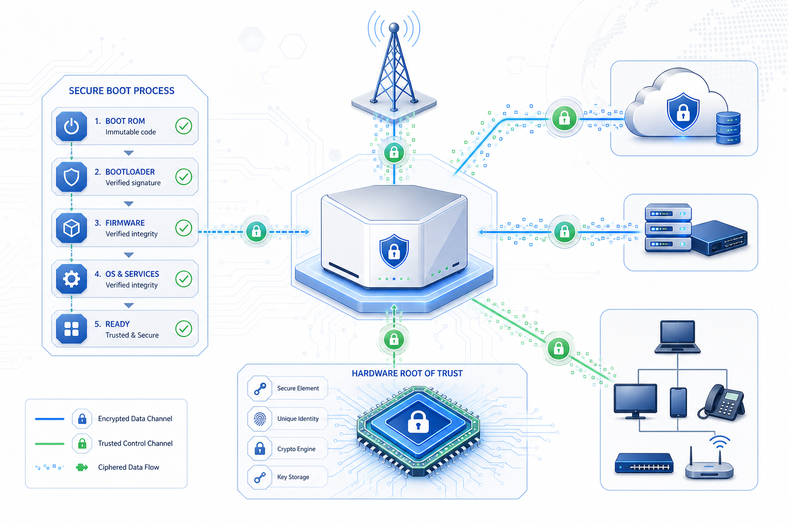
    The hardware root of trust (HRoT) is the immutable foundation upon which all other security properties depend. In a Zero Trust CPE, the HRoT is typically implemented as a dedicated security processor or a trusted execution environment (TEE) within the main SoC that operates independently of the application processor and maintains its own isolated memory space.

    The HRoT stores device-unique cryptographic keys provisioned during silicon manufacturing—often using physically unclonable function (PUF) technology that derives keys from sub-micron variations in the silicon itself, making extraction physically infeasible. These keys never leave the HRoT boundary and are used exclusively for internal cryptographic operations: signing measurements, unwrapping protected blobs, and establishing device identity.

    For CPE procurement, the minimum HRoT specification should include: compliance with GlobalPlatform TEE Protection Profile or equivalent, PUF-based or OTP-fused unique device key storage, a certified true random number generator (TRNG) for nonce and key generation, and physical tamper resistance meeting FIPS 140-3 Level 2 or higher. Devices that rely solely on software-based key storage or unprotected non-volatile memory for device identity should be disqualified from carrier-grade deployments.

    Secure Boot: Measured and Verified Execution

    Secure boot ensures that only authenticated software executes on the CPE from the moment power is applied. The process follows a chain of trust: the HRoT (immutable boot ROM) verifies the first-stage bootloader signature; the first-stage bootloader verifies the second-stage bootloader; the bootloader verifies the operating system kernel; and the kernel verifies each application and service before launch.

    Critically, enterprise-grade CPE should implement measured boot alongside verified boot. Where verified boot makes a binary allow/deny decision at each stage, measured boot records cryptographic hashes of every loaded component into Platform Configuration Registers (PCRs) within a Trusted Platform Module (TPM 2.0). These measurements can be remotely attested by the network operator to prove that the CPE is running an authorized software stack before granting network access.

    The TPM 2.0 integration requirements for carrier CPE should include: discrete or firmware TPM compliant with TCG PC Client Specification, support for SHA-256 and SHA-384 PCR banks, monotonic counters for replay protection, and NV storage for operator-provisioned policies. Integrated SoC-level TPM implementations (fTPM) are acceptable when backed by a TEE that isolates TPM operations from the rich OS, but discrete TPM (dTPM) provides stronger physical attack resistance.

    Firmware Attestation: Proving Integrity to the Network

    Remote attestation closes the Zero Trust loop by enabling the mobile network operator to cryptographically verify the CPE’s software state before allowing it to attach to the network. The process typically follows the IETF RATS (Remote ATtestation procedureS) architecture, which standardizes the roles of attester (the CPE), verifier (the operator’s attestation service), and relying party (the network access control function).

    At network attachment time, the CPE generates a signed attestation report containing its PCR values, device identity certificate, and a fresh nonce provided by the verifier to prevent replay attacks. The verifier compares the PCR values against a reference database of known-good measurements for each authorized firmware version. If the measurements match, the verifier issues an attestation result that the network access control function uses to grant differentiated access—full network access for attested devices, restricted access for devices running unrecognized but unmodified firmware, and no access for devices with tampered software.

    Procurement teams should specify support for: IETF RATS architecture with TPM-based attestation, X.509 device identity certificates (IEEE 802.1AR DevID) with PKI-based certificate lifecycle management, and operator-customizable reference measurement policies. The attestation client should support both network-attach-time and periodic runtime attestation to detect post-attach compromises.

    Transport Layer Security and Cryptographic Agility

    All traffic between the CPE and the 5G core traverses encrypted tunnels—IPsec for user plane traffic in most FWA architectures, complemented by TLS 1.3 for management plane communications (TR-069/TR-369, NETCONF, or proprietary ACS protocols). Zero Trust principles demand that these tunnels are established with mutual authentication bound to the device’s hardware identity, not just pre-shared keys that can be extracted from compromised firmware images.

    Cryptographic agility is equally important. As quantum computing threats mature, CPE platforms must support crypto-agile architectures that allow algorithms to be swapped without hardware replacement. NIST’s Post-Quantum Cryptography (PQC) standardization process completed its first round of algorithm selections in 2024, and CPE platforms shipping in 2026 should include hardware acceleration for CRYSTALS-Kyber (key encapsulation) and CRYSTALS-Dilithium (digital signatures) in addition to classical algorithms.

    Runtime Protection and Secure Updates

    Beyond the boot chain, Zero Trust CPE must maintain security during continuous operation. Key runtime requirements include: signed and encrypted over-the-air (OTA) firmware updates with rollback protection (anti-downgrade enforced by TPM monotonic counters), secure storage for operator credentials and enterprise VLAN configurations with hardware-binding that prevents extraction if the flash chip is physically removed, runtime integrity monitoring that detects unauthorized code modification or configuration tampering, and a hardware-enforced secure debug interface that requires cryptographic authentication before JTAG or UART access is granted.

    Evaluation Framework for Procurement

    The following checklist provides a structured framework for evaluating Zero Trust security capabilities in 5G CPE:

    • Hardware Root of Trust: PUF-based or OTP-fused unique device keys, certified TRNG, tamper-resistant key storage (FIPS 140-3 Level 2+)
    • Secure Boot Chain: Immutable boot ROM, staged verification from bootloader through application launch, measured boot with TPM 2.0 PCR logging
    • TPM Integration: TPM 2.0 (dTPM preferred, fTPM with TEE backup acceptable), SHA-256/384 PCR banks, NV storage for operator policies
    • Remote Attestation: IETF RATS-compliant attestation client, IEEE 802.1AR DevID certificates, customizable reference measurements, periodic runtime attestation
    • Mutual Authentication: Hardware-bound device identity for IPsec/TLS, PKI-based certificate management, crypto-agile architecture with PQC readiness
    • OTA Updates: Signed and encrypted firmware images, hardware-enforced rollback protection, atomic update with fallback partition
    • Runtime Defense: Secure credential storage with hardware binding, runtime integrity monitoring, authenticated debug interface

    Conclusion

    Zero Trust security is no longer optional for carrier-grade 5G CPE. As FWA deployments expand into enterprise verticals with stringent compliance requirements—finance, healthcare, energy, government—the security architecture of the CPE becomes a critical factor in both technical evaluation and regulatory compliance. Procurement teams that specify hardware-anchored Zero Trust capabilities today will avoid costly retrofit programs and security incidents as threat actors increasingly target the network edge.

    This guide is part of Honlly Telecom’s Technical Buyer’s Guide series. For detailed security specifications of Honlly’s 5G CPE platforms or to schedule a technical deep-dive with our security architecture team, please contact our enterprise solutions group.
  • Industrial-Grade 5G CPE Enclosure Design: IP67/IK08 Certification, Extended Temperature Operation, and Surge Protection Engineering for Mission-Critical Outdoor Deployments

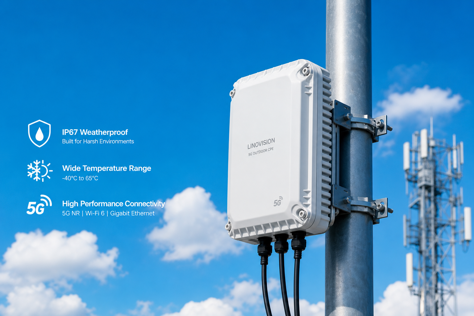
    Industrial-Grade 5G CPE Enclosure Design: IP67/IK08 Certification, Extended Temperature Operation, and Surge Protection Engineering for Mission-Critical Outdoor Deployments

    As 5G FWA deployments extend beyond climate-controlled indoor environments into outdoor, industrial, and remote locations, the physical enclosure design of the CPE device becomes a critical engineering discipline. Industrial-grade 5G CPE must withstand extreme temperatures, moisture ingress, dust contamination, physical impact, vibration, and electrical surge events — all while maintaining reliable multi-gigabit wireless connectivity. This article examines the key environmental certification standards, enclosure design principles, and procurement considerations for ruggedized 5G CPE in mission-critical B2B applications.

    Ingress Protection: IP67 and Beyond

    The IP (Ingress Protection) rating system, defined by IEC 60529, is the primary standard for evaluating enclosure resistance to solid particles and liquid ingress. For outdoor 5G CPE deployments, IP67 represents the practical minimum requirement — the “6” indicates complete protection against dust ingress (dust-tight), while the “7” guarantees protection against temporary immersion in water up to 1 meter depth for 30 minutes.

    However, industrial environments often demand more stringent protection. IP68 certification extends immersion depth beyond 1 meter (typically 1.5–3 meters, as specified by the manufacturer), while IP69K — originally developed for the automotive and food processing industries — provides protection against high-pressure, high-temperature water jets (80°C at 80–100 bar pressure). For CPE deployed in offshore energy platforms, mining operations, or food and beverage facilities, IP69K-rated enclosures ensure operational integrity despite aggressive washdown procedures and corrosive environmental exposure.

    The enclosure sealing strategy must address multiple ingress paths: cable glands and connector interfaces require compression seals with appropriate IP ratings; the SIM card access door needs double-gasket designs with captive fasteners; and ventilation membranes (typically ePTFE-based) must equalize internal pressure while blocking liquid and particulate ingress. Each sealing interface represents a potential failure point that must be validated through accelerated lifecycle testing.

    Impact Resistance: IK Rating Standards

    The IK rating system (IEC 62262) quantifies enclosure resistance to mechanical impact, measured in joules. IK08 (5 joules) is the common baseline for industrial CPE, equivalent to withstanding the impact of a 1.7 kg mass dropped from 300 mm. For deployments in construction sites, mining operations, transportation hubs, and public infrastructure, IK09 (10 joules) or IK10 (20 joules) ratings provide assurance against vandalism, falling debris, and accidental handling damage.

    Achieving high IK ratings requires careful material selection and structural design. Aluminum alloy enclosures (typically ADC12 or A380 die-cast aluminum) offer an optimal balance of impact resistance, thermal conductivity, and weight. The wall thickness, rib reinforcement patterns, and corner radius design must be optimized through finite element analysis (FEA) simulation to absorb impact energy without deforming internal component mounting points or compromising seal integrity.

    Polycarbonate and glass-reinforced polymer enclosures provide an alternative for applications requiring lighter weight or RF transparency. However, UV stabilization additives are essential to prevent polymer degradation from prolonged sun exposure. A 5-year UV aging test (per ISO 4892-2) with less than Delta-E 5 color shift and no significant reduction in impact resistance should be validated by the enclosure manufacturer.

    Extended Temperature Operation: From Arctic to Desert

    Industrial 5G CPE must operate reliably across extreme temperature ranges without active cooling. The industry benchmark for outdoor equipment is -40°C to +65°C operating temperature and -40°C to +85°C storage temperature, conforming to IEC 60068-2 environmental testing standards. Achieving this requires a holistic thermal management strategy encompassing component selection, thermal interface materials, and passive cooling design.

    At the component level, all integrated circuits — including the 5G modem, Wi-Fi chipset, Ethernet PHY, and power management IC — must be industrial-temperature-grade (-40°C to +85°C junction temperature). Memory components (LPDDR4X/LPDDR5 DRAM and eMMC/UFS storage) require similar industrial ratings. Electrolytic capacitors, which have limited low-temperature performance, should be replaced with solid polymer or MLCC alternatives in cold-climate designs.

    For high-temperature operation, the enclosure itself functions as a heat sink. Die-cast aluminum enclosures with integrated fin structures maximize surface area for convective and radiative heat dissipation. The thermal path from the 5G modem and application processor to the enclosure surface must minimize thermal resistance through the use of thermal gap pads, phase-change materials, or direct-die-contact thermal solutions. A maximum junction-to-ambient thermal resistance (Theta-JA) below 15°C/W for the primary SoC ensures stable operation at 65°C ambient without throttling.

    For extreme cold environments, self-heating strategies may be employed — using the modem and processor’s own power dissipation to warm internal components during startup. A cold-start sequence that gradually brings up power-hungry components while monitoring internal temperature sensors prevents condensation and thermal shock damage to solder joints and semiconductor packages.

    Surge Protection and Electrical Robustness

    Outdoor CPE installations face significant electrical hazards including lightning-induced surges, AC power cross events, and electrostatic discharge. Comprehensive surge protection must be implemented on all external interfaces: the power input (DC barrel jack or PoE), Ethernet ports, and antenna connectors.

    For Ethernet interfaces, compliance with ITU-T K.21 (basic-level surge protection, 1.5 kV) or the more stringent GR-1089-CORE (6 kV for ports, 5 kA for power feeds) is essential for carrier deployments. Gas discharge tubes (GDTs) provide the first line of defense against high-energy transients, with Transient Voltage Suppression (TVS) diode arrays clamping residual energy at the PHY level. The PCB layout must include sufficient creepage and clearance distances per IEC 60950-1/IEC 62368-1, with isolation slots where necessary to prevent arc-over between primary and secondary circuits.

    Power supply design must accommodate wide input voltage ranges (typically 12–57V DC for PoE PD applications, or 9–36V DC for direct DC input in vehicle and industrial applications) with reverse polarity protection, under-voltage lockout, and over-voltage shutdown. An isolated DC-DC converter topology (compliant with IEC 61800-5-1 for industrial drives when applicable) provides galvanic isolation between the power source and the CPE’s internal electronics.

    Corrosion Resistance and Material Durability

    For coastal deployments, marine environments, and chemical processing facilities, corrosion resistance becomes a primary enclosure design driver. Aluminum enclosures should receive chromate conversion coating (per MIL-DTL-5541 Type II Class 3) followed by polyester powder coating with a minimum 60-micron thickness. Salt spray testing per ASTM B117 for 500–1000 hours with no blistering or corrosion creep beyond 2 mm from scribe validates coating integrity.

    Stainless steel (304 or 316L grade) enclosures provide superior corrosion resistance for the most demanding environments but introduce RF shielding considerations that must be addressed through external antenna designs or RF-transparent window panels. All external fasteners should be stainless steel with appropriate thread-locking compounds to prevent galvanic corrosion at dissimilar metal junctions.

    Procurement Guidelines for Ruggedized 5G CPE

    B2B buyers evaluating industrial-grade 5G CPE should request comprehensive certification documentation including IP test reports from ISO 17025-accredited laboratories, IK impact test certificates, extended temperature validation data with thermal imaging analysis, surge compliance test reports, and corrosion resistance certification. Beyond certifications, field-proven deployment references in similar environmental conditions provide practical validation of enclosure design maturity.

    Total cost of ownership analysis should factor in the mean time between failures (MTBF) per Telcordia SR-332, expected enclosure service life (minimum 10 years for outdoor telecommunications equipment), and the availability of replacement seal kits and gaskets for periodic maintenance. A well-engineered industrial enclosure transforms 5G CPE from an indoor consumer device into a carrier-grade outdoor infrastructure element capable of delivering reliable connectivity in the world’s harshest operating environments.

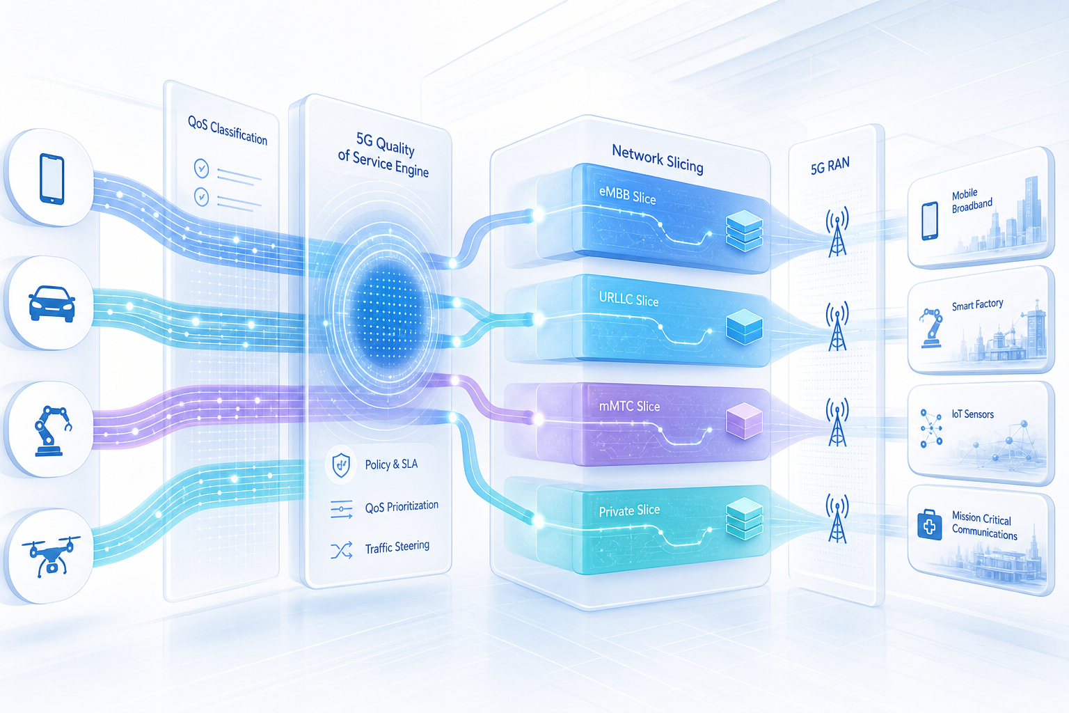
  • 5G CPE Quality of Service Architecture: Deep Dive into 5QI-to-DSCP Mapping, Slice-Aware Traffic Steering, and Deterministic Latency for Enterprise-Grade Application Assurance

    5G CPE Quality of Service Architecture: Deep Dive into 5QI-to-DSCP Mapping, Slice-Aware Traffic Steering, and Deterministic Latency for Enterprise-Grade Application Assurance

    As enterprise 5G FWA deployments scale globally, Quality of Service (QoS) architecture within CPE devices has emerged as a critical differentiator for B2B connectivity solutions. Unlike consumer-grade gateways that treat all traffic equally, enterprise 5G CPE must implement sophisticated QoS frameworks that preserve service-level agreements (SLAs) across diverse application workloads — from latency-sensitive voice and video conferencing to throughput-intensive cloud backup and IoT telemetry.

    Understanding the 5G QoS Model: 5QI and QoS Flows

    The 3GPP 5G QoS model is fundamentally flow-based, representing a significant evolution from the 4G LTE bearer-centric architecture. Each QoS Flow is identified by a QoS Flow Identifier (QFI) and associated with a 5G QoS Identifier (5QI) that defines standardized performance characteristics. The 5QI table specifies resource type (GBR, non-GBR, or delay-critical GBR), priority level, packet delay budget (PDB), packet error rate (PER), and averaging window — all of which must be honored end-to-end through the CPE.

    For enterprise CPE implementations, the critical challenge lies in mapping these 5QI-defined flows to the IP-layer Differentiated Services Code Point (DSCP) markings that enterprise routers, switches, and application servers actually understand. A well-designed 5QI-to-DSCP mapping strategy ensures that QoS treatment established at the 5G core is preserved as traffic exits the CPE into the enterprise LAN or SD-WAN overlay.

    5QI-to-DSCP Mapping: Bridging 3GPP and IETF QoS Models

    The mapping from 5QI values to DSCP markings is not standardized by 3GPP — it requires careful operator configuration based on the enterprise’s internal QoS policy. A typical enterprise mapping might associate conversational voice (5QI=1) with DSCP EF (46), real-time gaming and V2X (5QI=3) with DSCP CS5 (40), and low-latency eMBB applications with DSCP AF41 (34).

    Advanced CPE implementations go beyond static mapping tables by supporting configurable 5QI-to-DSCP translation with per-QoS-Flow granularity. This enables operators to differentiate between multiple non-GBR flows carrying different application types, each receiving appropriate DSCP marking before entering the enterprise network. The CPE must also handle the reverse direction — remarking DSCP values on inbound LAN traffic to appropriate QFIs for uplink transmission — ensuring bidirectional QoS consistency.

    Network Slicing and Slice-Aware Traffic Steering

    5G network slicing introduces an additional dimension to CPE QoS architecture. Each network slice, identified by Single Network Slice Selection Assistance Information (S-NSSAI), may contain multiple QoS Flows. The CPE must implement slice-aware traffic steering that routes application traffic to the appropriate slice based on operator-configured URSP (UE Route Selection Policy) rules.

    For enterprise deployments, this enables powerful use cases: a manufacturing facility might operate three concurrent slices — an ultra-reliable slice for industrial control systems (URLLC), a high-bandwidth slice for video surveillance and AR maintenance (eMBB), and a massive IoT slice for sensor networks (mMTC) — all through a single 5G CPE device. The CPE’s internal packet classifier must inspect application traffic (by destination IP, port, protocol, DNN, or application ID) and steer each flow to the correct slice while applying appropriate 5QI and DSCP treatment.

    Deterministic Latency and Time-Sensitive Networking Integration

    The convergence of 5G with Time-Sensitive Networking (TSN) standards, specified in 3GPP Release 17 and enhanced in Release 18, enables deterministic latency guarantees for industrial automation and critical infrastructure. The 5G CPE functions as a TSN translator, bridging the 5G system’s QoS framework with IEEE 802.1 TSN mechanisms including time-aware scheduling (802.1Qbv), frame preemption (802.1Qbu), and per-stream filtering and policing (802.1Qci).

    When configured as a DS-TT (Device-Side TSN Translator), the CPE maintains precise time synchronization via IEEE 802.1AS and enforces gate control lists that guarantee bounded latency for critical data streams. This capability is essential for applications like motion control in smart factories, power grid protection systems, and autonomous vehicle coordination — where latency variation must be measured in microseconds, not milliseconds.

    CPE Buffer Management and Congestion Avoidance

    Enterprise-grade 5G CPE devices must implement intelligent buffer management to prevent the well-known bufferbloat problem from degrading latency-sensitive application performance. Active Queue Management (AQM) algorithms — such as CoDel (Controlled Delay), FQ-CoDel (Fair Queuing CoDel), or CAKE (Common Applications Kept Enhanced) — should be applied to the CPE’s WAN interface to maintain low queuing latency under load.

    Per-flow queuing with hierarchical token bucket (HTB) scheduling ensures fair bandwidth allocation across competing application flows, preventing a single bulk transfer from starving interactive traffic. For SD-WAN integrated CPEs, the QoS scheduler must coordinate with the overlay’s application-aware routing to ensure that traffic steered across the 5G link receives appropriate priority treatment throughout the entire path.

    Procurement Checklist for Enterprise QoS-Capable 5G CPE

    When evaluating 5G CPE solutions for QoS-sensitive enterprise deployments, B2B buyers should assess: support for configurable 5QI-to-DSCP mapping with per-flow granularity; URSP-based slice-aware traffic steering; integrated AQM with FQ-CoDel or equivalent; TSN translator capability for industrial applications; TR-369 USP remote management for QoS policy provisioning; and hardware offload for QoS processing at multi-gigabit throughput rates without CPU contention.

    A well-architected QoS framework within the 5G CPE is not merely a feature checkbox — it is the foundation upon which enterprise SLAs, application performance guarantees, and ultimately customer satisfaction are built. As 5G FWA continues its rapid expansion into enterprise verticals, QoS sophistication will increasingly separate carrier-grade CPE from consumer-grade alternatives.

  • Cloud-Managed 5G CPE: TR-369 USP Evolution, Zero-Touch Provisioning, and Multi-Tenant Device Management for Global Telecom Operators

    Cloud-Managed 5G CPE: TR-369 USP Evolution, Zero-Touch Provisioning, and Multi-Tenant Device Management for Global Telecom Operators

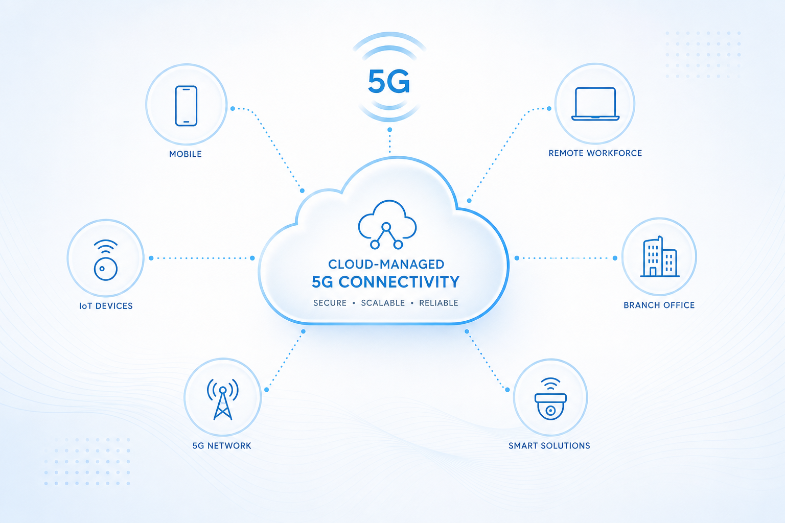
    The operational paradigm for managing 5G fixed wireless access (FWA) customer premises equipment (CPE) at carrier scale is undergoing a fundamental transformation. As operator CPE fleets expand from thousands to millions of deployed devices, the legacy TR-069 (CWMP) protocol and on-premises ACS (Auto Configuration Server) architectures that served the DSL and early fiber era are giving way to cloud-native, TR-369 USP (User Services Platform)-based management frameworks. For telecom operators, MVNOs, and wholesale CPE buyers, understanding this evolution is critical for making informed procurement and deployment decisions in 2026 and beyond.

    From TR-069 to TR-369 USP: A Generational Shift

    The Broadband Forum’s TR-069 protocol (CWMP) has been the workhorse of broadband CPE management for nearly two decades, providing remote configuration, firmware upgrade, and diagnostic capabilities across hundreds of millions of devices. However, TR-069 was designed in an era of single-service DSL connections and presents fundamental limitations for modern multi-service 5G FWA deployments: its XML/SOAP-based messaging is bandwidth-intensive and processing-heavy; its connection model requires the ACS to initiate sessions through NAT traversal; and its data model lacks native support for the complex multi-WAN, network slicing, and IoT gateway functions of modern 5G CPE.

    TR-369 USP, standardized by the Broadband Forum in 2020 and now reaching widespread implementation maturity, addresses these limitations with a fundamentally modernized architecture. USP uses a binary-protocol-over-WebSocket or CoAP transport, supports both controller-initiated and agent-initiated messaging, enables bulk data collection through the scalable USP Record mechanism, and provides native IoT device proxy capabilities. Critically, USP is designed for cloud-native deployment—its microservices-friendly architecture aligns with the Kubernetes-orchestrated, horizontally scalable management platforms that Tier-1 operators are now deploying.

    Zero-Touch Provisioning: The ZTP Revolution

    One of the most transformative operational benefits of modern cloud-managed CPE platforms is zero-touch provisioning (ZTP). In the TR-069 era, CPE onboarding typically required manual intervention: pre-configuration at a staging facility, customer-side technician visits, or phone-based guided setup. With TR-369 USP and cloud-native management, operators can achieve true zero-touch deployment: the CPE boots, connects to any available WAN interface (5G, LTE, Ethernet), discovers its management controller via DHCP options, DNS SRV records, or pre-loaded bootstrap URLs, authenticates using device certificates or IMEI/ICCID-based identity, and automatically downloads its full service configuration—all without human intervention.

    For B2B operators deploying CPE at thousands of enterprise customer sites simultaneously, ZTP reduces deployment costs by an estimated 40-60% compared to staged or truck-roll provisioning models. Major CPE chipset vendors including Qualcomm (through its Device Management Framework) and MediaTek (via its Cloud CPE SDK) now provide integrated ZTP bootstrap libraries that simplify USP agent implementation for ODM/OEM manufacturers.

    Multi-Tenant Architecture for Wholesale and MVNO Deployments

    A critical capability that cloud-managed platforms bring to the B2B CPE ecosystem is true multi-tenancy. In wholesale and MVNO business models—increasingly common in the 5G FWA market—a single CPE hardware SKU may be deployed across multiple service provider tenants, each requiring isolated management visibility, distinct configuration profiles, and tenant-specific firmware branches. Cloud-native USP controllers implement tenant isolation at the platform layer, enabling a single management infrastructure to serve multiple operator customers while maintaining strict data and configuration separation.

    This multi-tenant architecture also simplifies the CPE supply chain: wholesale buyers can procure a single, cloud-manageable CPE model and assign devices to downstream operator tenants through software configuration alone—eliminating the need for per-operator hardware variants and reducing inventory complexity.

    Security Architecture for Cloud-Managed CPE

    The shift to cloud-based CPE management introduces heightened security requirements. Modern TR-369 USP implementations mandate mutual TLS (mTLS) authentication between the CPE agent and the USP controller, with X.509 device certificates provisioned at manufacturing time or during initial bootstrap. The USP protocol also defines end-to-end message security, role-based access control (RBAC) for multi-tenant controller access, and secure software module management for verified firmware updates.

    For procurement teams evaluating cloud-managed CPE solutions, security certification is paramount. Key certifications to look for include Broadband Forum BBF.369 USP certification, GSMA NESAS (Network Equipment Security Assurance Scheme) compliance for 5G devices, and relevant regional security certifications such as EUCC (EU) and FIPS 140-3 (North America).

    Procurement Considerations for 2026-2027

    When selecting cloud-manageable 5G CPE for carrier-grade deployments, B2B buyers should evaluate the following criteria:

    • USP protocol compliance: Full TR-369 USP 1.2+ support with USP Record, USP Bulk Data Collection, and USP Firmware Management modules.
    • Controller ecosystem compatibility: Certification with leading USP controller platforms including Axiros AXESS, Friendly Technologies, AOUSD, and open-source solutions like OB-USP-Agent.
    • ZTP maturity: Support for DHCP Option 43/60, DNS-based discovery (RFC 6763), and pre-loaded bootstrap URL mechanisms with secure device identity provisioning.
    • Multi-WAN management: Ability to manage 5G NR, LTE, Ethernet WAN, and Wi-Fi backhaul interfaces through a unified USP data model.
    • Analytics and telemetry: Support for streaming telemetry (gNMI/gRPC alongside USP) and integration with operator big-data platforms for AI-driven predictive maintenance.
    • Firmware lifecycle: A/B partition firmware architecture with USP-managed secure OTA updates and automated rollback capabilities.

    The transition from TR-069 to TR-369 USP represents more than a protocol upgrade—it is a strategic platform shift that enables operators to manage exponentially larger CPE fleets with lower operational overhead, faster service velocity, and richer customer experience analytics. For B2B buyers, selecting cloud-native, USP-compliant CPE today is an investment in operational scalability that will pay dividends through the 5G-Advanced and 6G eras ahead.

  • 5G CPE for Enterprise SD-WAN Integration: IPSec Acceleration, WireGuard Performance, and Hybrid WAN Overlay Architecture

    5G CPE for Enterprise SD-WAN Integration: IPSec Acceleration, WireGuard Performance, and Hybrid WAN Overlay Architecture

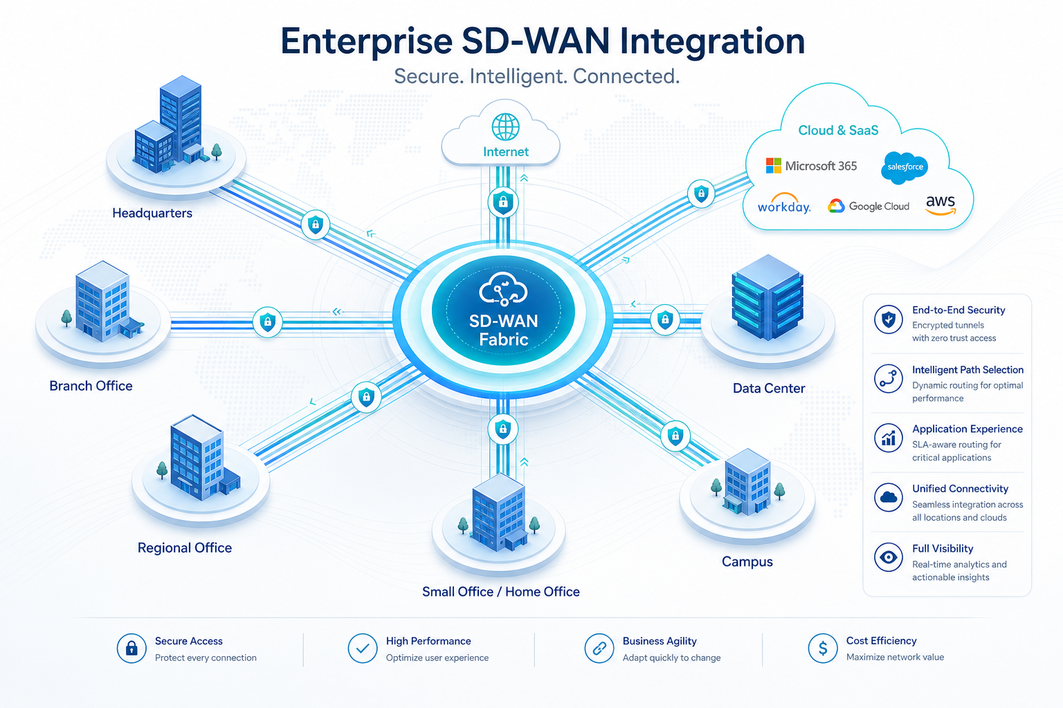
    As enterprise branch connectivity strategies evolve beyond MPLS-centric architectures, the convergence of 5G fixed wireless access (FWA) and software-defined wide-area networking (SD-WAN) has emerged as one of the most significant architectural shifts in enterprise networking. 5G CPE devices are no longer simple modem-to-Ethernet bridges—they are becoming intelligent SD-WAN edge nodes that integrate WAN link aggregation, application-aware traffic steering, and hardware-accelerated VPN termination. For enterprise IT teams and managed service providers (MSPs) architecting next-generation branch connectivity, understanding the integration patterns between 5G CPE and SD-WAN is essential.

    The 5G CPE as an SD-WAN Edge Platform

    Modern enterprise-grade 5G CPE devices have evolved significantly beyond the consumer-grade fixed wireless terminals of the early 5G era. High-end CPE platforms now integrate multi-core ARM or x86 processors, hardware security engines, and sufficient memory to run full SD-WAN software stacks directly on the CPE—eliminating the need for a separate SD-WAN appliance at the branch edge. This consolidation delivers several advantages: reduced hardware footprint and power consumption, simplified deployment (a single device to install and manage), and tighter integration between WAN link telemetry and SD-WAN policy enforcement.

    Key hardware capabilities that enable this convergence include: integrated hardware crypto accelerators supporting AES-GCM, SHA-256, and public-key operations at multi-gigabit line rates; dedicated traffic management engines with hierarchical QoS (HQoS) supporting per-application, per-tunnel, and per-interface queuing; and multi-WAN architectures that combine 5G NR, LTE, Ethernet, and Wi-Fi backhaul interfaces within a single CPE platform.

    IPSec and WireGuard Performance Considerations

    VPN overlay performance is the critical metric for SD-WAN-integrated 5G CPE. Enterprises running latency-sensitive applications (VoIP, video conferencing, real-time trading) and high-throughput workloads (file replication, cloud backup, VDI) require the CPE to sustain near-line-rate encrypted throughput across concurrent tunnels. Two VPN protocols dominate the 5G CPE SD-WAN landscape:

    IPSec: The incumbent enterprise VPN standard, IPSec benefits from decades of optimization and widespread hardware offload support. Modern 5G CPE chipsets from Qualcomm (IPQ series networking processors) and MediaTek (Filogic platforms) include dedicated IPSec crypto engines capable of sustaining 2-5 Gbps of AES-256-GCM encrypted throughput. For enterprises with existing IPSec-based SD-WAN deployments (Cisco SD-WAN/Viptela, VMware VeloCloud, Fortinet Secure SD-WAN), selecting a CPE with hardware IPSec offload ensures compatibility while maintaining performance.

    WireGuard: The newer, streamlined VPN protocol has gained rapid adoption in SD-WAN due to its minimal codebase, simplified key management, and excellent software performance even without hardware offload. WireGuard’s use of ChaCha20-Poly1305 encryption can achieve 1.5-3 Gbps on mid-range CPE processors without dedicated crypto hardware. Several next-generation SD-WAN platforms—including NetFoundry, ZeroTier, and the open-source FlexiWAN project—have adopted WireGuard as their primary overlay protocol. For greenfield 5G SD-WAN deployments, WireGuard’s operational simplicity and strong security posture make it an increasingly compelling choice.

    Hybrid WAN Overlay Architecture

    The most advanced 5G CPE SD-WAN deployments implement a hybrid overlay architecture that combines multiple VPN technologies and WAN interfaces into a unified, policy-driven forwarding plane. In this model:

    • Underlay abstraction: The CPE treats 5G NR, LTE, Ethernet, and satellite links as abstract WAN transports, each characterized by real-time metrics (bandwidth, latency, jitter, packet loss, signal quality).
    • Overlay mesh: IPSec and WireGuard tunnels are established over each viable WAN link to the enterprise SD-WAN hub or cloud gateway, creating a full-mesh or hub-spoke overlay topology.
    • Application-aware steering: The SD-WAN policy engine classifies traffic using deep packet inspection (DPI), application signatures, and DNS-based identification, then steers each flow to the optimal overlay tunnel based on application requirements and real-time link quality.
    • Intelligent failover: Sub-second link failure detection—leveraging BFD (Bidirectional Forwarding Detection), continuous tunnel health probes, and physical-layer signal monitoring—triggers seamless failover to alternate WAN paths without session interruption.

    Deployment Scenarios Driving Adoption in 2026

    Several enterprise verticals are driving accelerated adoption of SD-WAN-integrated 5G CPE:

    Retail and Quick-Service Restaurants (QSR): Thousands of distributed locations require reliable PCI-compliant connectivity for POS systems, inventory management, and guest Wi-Fi. 5G CPE with integrated SD-WAN provides primary or failover connectivity that deploys in hours rather than the weeks required for wired circuits.

    Financial Services Branch Banking: Bank branches demand always-on connectivity with strict SLA guarantees for real-time transaction processing. Dual-5G CPE with SD-WAN enables active-active WAN configurations with encrypted overlay tunnels to redundant data centers, ensuring zero-downtime connectivity for mission-critical banking applications.

    Healthcare Clinics and Telemedicine: Remote clinics and pop-up healthcare facilities leverage 5G CPE with SD-WAN for HIPAA-compliant connectivity, with application-aware policies that prioritize telemedicine video traffic over administrative workloads during clinical hours.

    Temporary and Pop-Up Sites: Construction sites, event venues, and disaster recovery operations use ruggedized 5G CPE with embedded SD-WAN for rapid-deployment connectivity that can be operational within minutes of power-on.

    Procurement Checklist for SD-WAN-Capable 5G CPE

    For enterprise IT and MSP procurement teams evaluating 5G CPE for SD-WAN integration, the following checklist provides a structured evaluation framework:

    • Hardware IPSec throughput rating at AES-256-GCM with 1400-byte IMIX packets
    • WireGuard performance with ChaCha20-Poly1305 at typical IMIX traffic profiles
    • Maximum concurrent VPN tunnel count and tunnel establishment rate
    • Certification status with target SD-WAN platform (vendor-specific interoperability testing)
    • Support for BFD and sub-second failover across 5G, LTE, and Ethernet WAN interfaces
    • DPI engine capability and application signature database update mechanism
    • Centralized management integration (SD-WAN orchestrator API or TR-369 USP telemetry)
    • Hardware root of trust and secure key storage (TPM 2.0 or equivalent)
    • Thermal design for sustained multi-gigabit encrypted throughput without throttling

    The convergence of 5G FWA and SD-WAN represents a strategic opportunity for enterprises to simplify branch networking architecture, accelerate site deployment, and improve WAN resilience—all while reducing the hardware footprint and operational complexity of traditional multi-box branch edge solutions. As 5G network coverage expands and CPE platforms continue to mature, integrated 5G CPE SD-WAN solutions will become the default branch connectivity architecture for distributed enterprises worldwide.

  • 5G NR-U and Unlicensed Spectrum CPE: Expanding Private Network Capacity Through License-Assisted Access and Standalone Unlicensed Operation

    5G NR-U and Unlicensed Spectrum CPE: Expanding Private Network Capacity Through License-Assisted Access and Standalone Unlicensed Operation

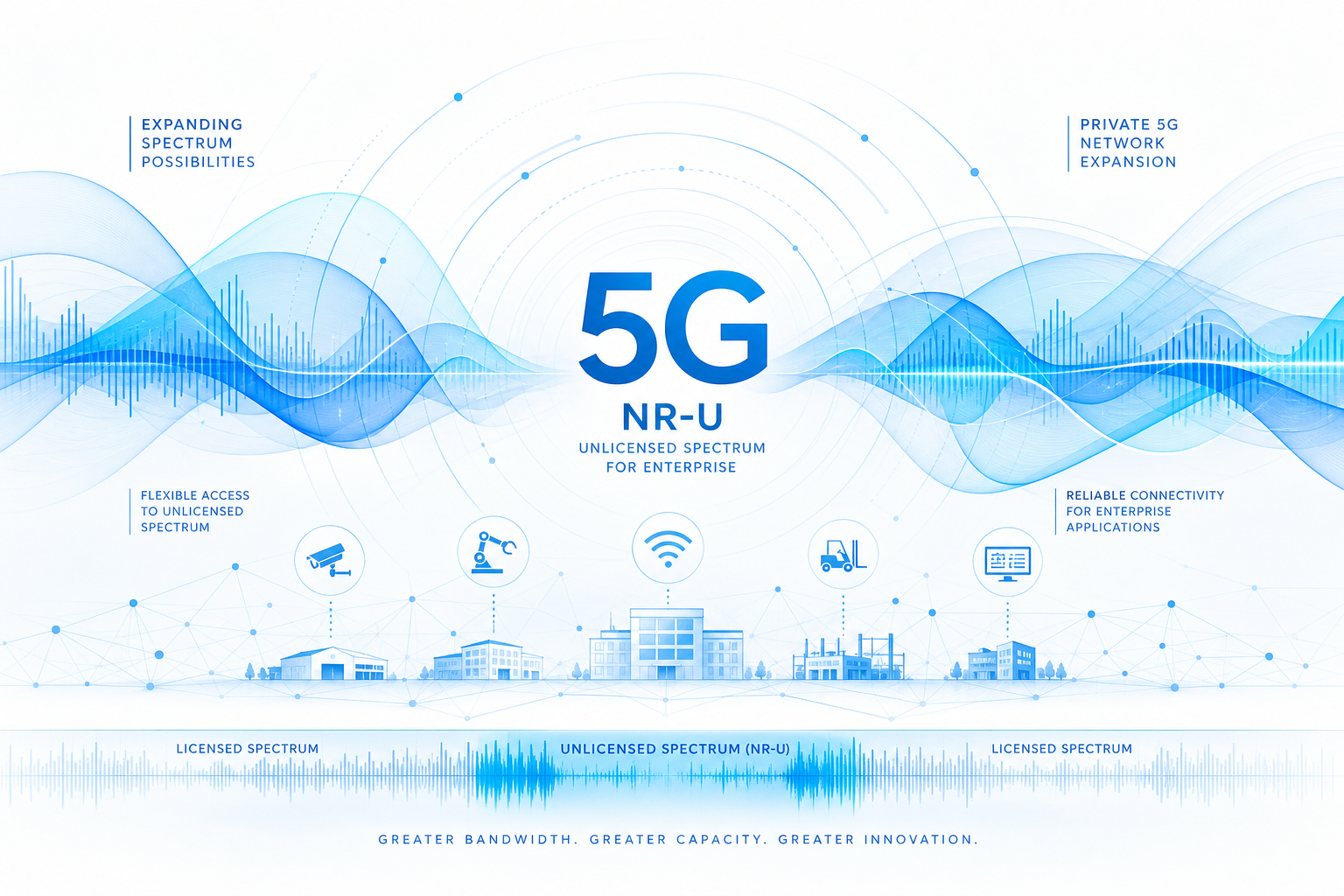
    Spectrum remains the single most constrained resource in wireless networking. While licensed spectrum offers guaranteed quality of service, its limited availability — especially for private network operators — has long been a bottleneck for enterprise 5G adoption. 5G NR-U (New Radio Unlicensed) changes this equation by extending 5G operation into globally available unlicensed bands, dramatically expanding the capacity envelope for private and enterprise 5G deployments.

    Understanding NR-U: Two Operational Modes

    3GPP Release 16 introduced NR-U with two distinct operational modes, each serving different deployment scenarios: License-Assisted Access (LAA): In this mode, a licensed 5G anchor carrier provides the control plane and guaranteed capacity, while NR-U carriers operating in the 5 GHz unlicensed band supplement downlink and uplink throughput. The anchor carrier handles mobility, authentication, and QoS enforcement; NR-U carriers provide pure capacity augmentation. This is the most common initial NR-U deployment model and is supported by major infrastructure vendors including Ericsson, Nokia, and Samsung. Standalone NR-U (SA NR-U): The more radical architecture — NR-U operates entirely in unlicensed spectrum without any licensed anchor. SA NR-U is particularly attractive for private network operators who may not hold licensed spectrum at all. It enables fully independent 5G deployments in the 5 GHz and emerging 6 GHz bands, subject to regional regulatory frameworks.

    Why NR-U Matters for Enterprise and Private 5G

    The business case for NR-U in private 5G CPE deployments rests on three pillars: Spectrum cost elimination: Licensed spectrum — whether acquired at auction, leased from MNOs, or obtained through local regulatory processes (such as Germany’s 3.7-3.8 GHz local licenses) — represents a significant recurring cost. NR-U sidesteps this entirely by operating in license-exempt bands, dramatically lowering the total cost of ownership for private network operators. Capacity multiplication: A private 5G network operating in 100 MHz of licensed n78 spectrum can add up to 500 MHz of NR-U capacity in the 5 GHz band alone (where available), plus additional bandwidth as regulators open the 6 GHz band (5925-7125 MHz) for license-exempt use. For bandwidth-hungry industrial applications — automated optical inspection, 4K/8K video surveillance, AR-assisted maintenance — this capacity headroom is transformative. Global harmonization: Unlike licensed spectrum, which varies dramatically by country, the 5 GHz band is globally available. NR-U CPE can be deployed in nearly any market without waiting for local spectrum licensing — a critical advantage for multinational enterprises standardizing on a single private network architecture.

    Coexistence Mechanisms: Fair Sharing with Wi-Fi

    A persistent concern around NR-U is coexistence with incumbent Wi-Fi networks sharing the same unlicensed bands. The 3GPP addressed this directly with sophisticated channel access mechanisms designed to ensure fair spectrum sharing: LBT (Listen Before Talk): NR-U devices must sense the channel and confirm it is clear before transmitting — the same fundamental mechanism used by Wi-Fi. 3GPP adopted LBT parameters (Category 4 LBT with exponential backoff) that are functionally equivalent to Wi-Fi’s CSMA/CA, ensuring neither technology dominates the channel unfairly. CO sharing and MCOT: NR-U supports Channel Occupancy Time sharing, where a base station acquires the channel and can share it with connected CPE devices within the same Maximum Channel Occupancy Time. This improves scheduling efficiency without disadvantaging neighboring Wi-Fi networks. Wideband operation and BWP adaptation: NR-U CPE can operate across wide bandwidths (up to 100 MHz carriers) while dynamically adapting Bandwidth Part (BWP) configurations to avoid congested sub-channels — effectively steering around heavy Wi-Fi traffic in real time.

    CPE Design Considerations for NR-U

    Building effective NR-U CPE requires addressing several engineering challenges beyond standard 5G CPE design: Dual-band RF front-end: NR-U CPE must support simultaneous operation in licensed bands (n77/n78/n79) and unlicensed bands (n46 at 5 GHz, and emerging n96/n102 at 6 GHz). This requires dual-concurrent RF chains with high isolation to prevent self-interference, plus advanced filtering to reject adjacent Wi-Fi signals. Dynamic spectrum sharing intelligence: The CPE software stack must make real-time decisions about which spectrum resources to use — licensed, unlicensed, or both — based on traffic QoS requirements, channel occupancy measurements, and operator policy. This demands a sophisticated spectrum management layer integrated with the 5G protocol stack. Regulatory agility: Unlicensed spectrum regulations vary by region (FCC Part 15 in the US, ETSI EN 301 893 in Europe, MIC ordinances in Japan). NR-U CPE must support regional regulatory profiles that can be activated via configuration rather than requiring hardware variants.

    Deployment Scenarios Gaining Traction

    Several real-world NR-U deployment patterns are emerging: Smart manufacturing campuses: Automotive and electronics manufacturers are combining licensed private 5G (for AGV control, safety systems) with NR-U capacity (for video inspection, environmental monitoring). The licensed anchor ensures deterministic latency for critical control loops; NR-U provides scalable bandwidth for data-intensive applications. Higher education and research campuses: Universities deploying private 5G for research and smart campus applications are leveraging NR-U to extend coverage into buildings and outdoor spaces where running additional licensed small cells would be cost-prohibitive. Port and logistics hubs: Container terminals, airports, and distribution centers — environments where spectrum licensing is often complex due to cross-jurisdictional coverage — are deploying NR-U CPE for asset tracking, autonomous vehicle connectivity, and real-time inventory systems without spectrum acquisition delays.

    Strategic Implications for B2B Buyers

    For enterprises and system integrators planning private 5G deployments, NR-U capability should be a core CPE evaluation criterion. The technology effectively future-proofs the network investment: as regulators continue to release unlicensed spectrum (the 6 GHz band alone represents up to 1200 MHz of new capacity), NR-U-capable CPE can absorb this capacity without hardware replacement. Vendors like Honlly Telecom are already shipping 5G CPE platforms with NR-U-ready RF architectures, preparing for the moment when regulators in key markets — particularly Southeast Asia, the Middle East, and Latin America — finalize their 6 GHz unlicensed frameworks. For B2B buyers, selecting NR-U-capable CPE today ensures that tomorrow’s spectrum bounty translates directly into network capacity, not hardware obsolescence.
  • Multi-WAN 5G CPE Architectures for Enterprise Business Continuity: SD-WAN Integration, Intelligent Link Aggregation, and Carrier-Grade Failover Design

    Multi-WAN 5G CPE Architectures for Enterprise Business Continuity: SD-WAN Integration, Intelligent Link Aggregation, and Carrier-Grade Failover Design

    Enterprise network architects face a deceptively simple requirement: the connection must never go down. A retail chain processing thousands of POS transactions per minute, a logistics hub coordinating real-time fleet telemetry, a financial services branch handling regulatory reporting — in each case, connectivity downtime translates directly to revenue loss, SLA violations, and operational disruption. Multi-WAN 5G CPE has emerged as the architectural answer to this requirement, combining cellular WAN diversity with intelligent traffic steering to deliver carrier-grade resilience at enterprise price points.

    Beyond Simple Failover: The Multi-WAN Value Proposition

    First-generation 4G backup solutions treated cellular as a secondary, best-effort path — activated only when the primary wired link failed, often with 30 to 90 seconds of cutover delay. Modern multi-WAN 5G CPE architectures fundamentally rethink this model. Today’s enterprise-grade platforms support simultaneous active-active operation across two or more WAN interfaces — typically combining 5G cellular, fixed-line broadband, and dedicated fiber — with intelligent traffic distribution based on application type, link quality, and business policy. This moves cellular from backup to peer, unlocking: Bandwidth aggregation: Multiple WAN links contribute to total available throughput. A branch office with 500 Mbps fiber and dual 5G links at 300 Mbps each can present approximately 1.1 Gbps of usable capacity to the LAN side. Sub-second failover: BFD (Bidirectional Forwarding Detection) and link-quality probes running at 100ms intervals detect path degradation before connections drop, enabling hitless failover that preserves VoIP calls, video conferences, and TCP sessions. Application-aware steering: Latency-sensitive traffic (voice, video, real-time trading) routes over the lowest-jitter path. Bulk data (cloud backups, software updates) uses the cheapest available link. Business-critical SaaS applications receive dedicated bandwidth guarantees.

    SD-WAN Integration: The Intelligence Layer

    The true power of multi-WAN 5G CPE is unlocked when integrated with SD-WAN overlay platforms. Leading SD-WAN vendors — including VMware (Broadcom), Fortinet, Cisco, and Aruba — now support 5G CPE as first-class WAN transport endpoints. Key integration patterns include: Tunnel bonding and per-packet steering: SD-WAN edge software creates encrypted overlay tunnels over each physical WAN link. The tunnel bonding function stripes packets across available paths at millisecond granularity, compensating for individual link jitter and loss. If a 5G link experiences a transient 2% packet loss spike, the SD-WAN controller shifts affected flows to the fiber path within 200ms — transparent to the application layer. Zero-touch provisioning over cellular: Branch CPE can be drop-shipped directly to the deployment site. On first power-up, the device establishes a 5G connection, authenticates with the SD-WAN orchestrator, downloads its configuration, and joins the overlay fabric — all without on-site IT staff. This collapses traditional branch deployment timelines from weeks to hours. Cloud on-ramp optimization: With enterprises accelerating SaaS and IaaS adoption, SD-WAN-integrated 5G CPE can route cloud-destined traffic directly to the nearest cloud exchange point (AWS Direct Connect, Azure ExpressRoute, Google Cloud Interconnect) rather than backhauling through a central data center — dramatically reducing cloud application latency.

    Carrier Diversity: The Hidden Resilience Dimension

    A critical but often overlooked aspect of multi-WAN design is carrier diversity. Dual SIM slots supporting different MNOs (Mobile Network Operators) ensure that a single carrier outage does not disable the cellular backup path. Advanced 5G CPE platforms now support: Dual-SIM Dual-Active (DSDA): Both SIMs maintain simultaneous RRC-connected states, enabling true active-active cellular operation. If MNO A experiences a local RAN failure, traffic shifts to MNO B without the 5-15 second re-attach delay typical of Dual-SIM Single-Standby (DSSS) architectures. Cross-RAT fallback: When 5G NR coverage is unavailable, the CPE automatically falls back to LTE-A or even 3G while maintaining the SD-WAN overlay — ensuring basic business continuity even in coverage-edge scenarios common in rural and industrial deployments. Geographic path diversity: In fixed wireless access configurations, external antenna placement can connect to different cell towers for each 5G modem, providing physical path diversity that protects against tower-level failures or localized interference.

    Procurement Considerations for Enterprise Buyers

    When evaluating multi-WAN 5G CPE for enterprise deployment, IT procurement teams should prioritize: SD-WAN ecosystem certification: Verify that the CPE platform is certified by your chosen SD-WAN vendor. Certification ensures validated interoperability, supported configuration templates, and access to vendor TAC (Technical Assistance Center) for joint troubleshooting. Throughput headroom: Multi-WAN aggregation imposes CPU and forwarding-engine overhead. Select platforms with rated throughput at least 30% above aggregate WAN capacity to maintain line-rate performance during failover events and traffic bursts. Management plane integration: The CPE should expose a well-documented RESTCONF/NETCONF or gNMI interface for SD-WAN orchestrator integration. Avoid platforms that require proprietary management consoles that cannot be automated at scale. Thermal and environmental ratings: Active-active dual-5G operation generates significantly more heat than single-radio designs. For industrial or outdoor deployments, verify extended temperature range (-20°C to +60°C) and passive cooling capability.

    The Road Ahead: AI-Driven Predictive Path Selection

    The next evolution in multi-WAN 5G CPE is already visible in early deployments. Machine learning models trained on per-link telemetry data (signal quality, latency, jitter, throughput history, time-of-day patterns) can predict link degradation 30-60 seconds before it impacts applications — and proactively shift traffic before users notice. Combined with 5G-Advanced features like network slicing and URLLC, these intelligent multi-WAN platforms will form the connectivity backbone for the next generation of distributed enterprise applications — from autonomous warehouse robotics to real-time augmented reality field service. For enterprise buyers building infrastructure that must last 5-7 years, multi-WAN 5G CPE with SD-WAN integration is not an optional upgrade; it is the architectural minimum.
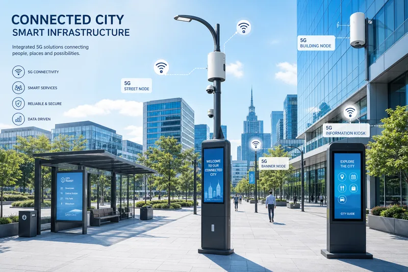
  • Smart City 5G FWA CPE Deployments: Municipal Infrastructure Models and Scalable Urban Connectivity Frameworks

    Smart City 5G FWA CPE Deployments: Municipal Infrastructure Models and Scalable Urban Connectivity Frameworks

    Smart city initiatives worldwide are entering a new phase of connectivity-driven transformation in 2026, with 5G Fixed Wireless Access emerging as a foundational infrastructure layer for municipal digital services. From intelligent traffic management and public safety networks to environmental monitoring and digital inclusion programs, city governments are discovering that 5G FWA CPE deployments offer a compelling combination of rapid deployment, scalable capacity, and manageable total cost of ownership compared with fiber-only buildout strategies.

    The Smart City Connectivity Challenge

    Cities pursuing comprehensive digital transformation face a fundamental infrastructure challenge: connecting thousands of distributed endpoints—traffic cameras, environmental sensors, digital signage, public Wi-Fi access points, emergency communication nodes, and smart utility meters—across diverse urban terrain. Traditional fiber backhaul provides ideal performance but entails prohibitive civil engineering costs and deployment timelines when extended to every endpoint location. Cellular-based connectivity using 5G FWA CPE bridges this gap, delivering fiber-like performance with installation timelines measured in hours rather than months.

    The economic case is compelling. Municipal fiber trenching in urban environments typically costs $250-$750 per meter, depending on surface conditions, utility congestion, and permitting complexity. A single smart city deployment requiring connectivity to 500 distributed locations could face fiber backhaul costs exceeding $15 million. By contrast, 5G FWA CPE installation at these locations, leveraging existing macro-cell and small-cell infrastructure, can deliver equivalent connectivity at 10-20% of the fiber-only cost while enabling immediate service activation.

    Municipal Deployment Architectures

    Smart city 5G FWA deployments typically follow one of three architectural models, each suited to different municipal priorities and existing infrastructure profiles. The operator-partnered model leverages commercial mobile network operator (MNO) infrastructure, with the municipality procuring CPE devices and service contracts through a managed services agreement. This model minimizes upfront infrastructure investment and is popular among mid-sized cities with existing MNO coverage.

    The municipal private network model involves the city deploying its own 5G infrastructure—typically using shared or licensed spectrum in the 3.5 GHz or 4.9 GHz bands—with CPE devices connecting directly to city-owned gNodeBs. This approach offers greater control over coverage, capacity allocation, security policy, and service prioritization, making it attractive for large metropolitan areas with dedicated smart city budgets and in-house technical expertise.

    The hybrid neutral-host model represents an emerging third path, where the municipality deploys shared infrastructure that serves both city services and commercial MNO traffic. In this model, CPE devices connect through a common RAN infrastructure with network slicing separating municipal and commercial traffic flows. This approach optimizes infrastructure utilization and can generate revenue through MNO colocation fees, offsetting municipal deployment costs.

    Use Case Specifics: CPE Requirements by Municipal Application

    Different smart city applications impose distinct requirements on CPE hardware. Intelligent traffic management systems demand outdoor-rated CPE with wide operating temperature ranges (-40°C to +65°C), Power over Ethernet (PoE) capability for integrated camera and sensor power delivery, and low-latency connectivity (<10ms) for real-time traffic signal coordination and emergency vehicle preemption.

    Public safety and emergency response networks require CPE with hardened security features including hardware root of trust, secure boot, and encrypted management channels. These deployments often mandate redundant connectivity paths—typically 5G primary with 4G LTE fallback—and battery backup capability ensuring operation during power outages. Some jurisdictions now specify compliance with public safety-grade reliability standards such as 99.999% availability for critical communication nodes.

    Environmental monitoring networks typically deploy large numbers of sensor-equipped CPE devices across wide geographic areas. These applications prioritize low power consumption, compact form factors suitable for pole-mount or underground-vault installation, and support for narrowband IoT (NB-IoT) or LTE-M protocols alongside 5G for sensor backhaul aggregation. Cost sensitivity is particularly acute given the high device counts involved—a city-wide air quality monitoring network may require 500 to 2,000 sensor nodes.

    Digital Inclusion and Public Broadband

    An increasingly prominent smart city use case is municipal broadband programs using 5G FWA to address digital divide challenges. Cities in North America, Europe, and Asia-Pacific are deploying 5G FWA CPE to connect underserved households, public housing complexes, and community centers, often subsidizing service costs through universal service funds or municipal broadband initiatives.

    These programs require CPE devices that balance performance with affordability and ease of deployment. Self-installable indoor CPE units are strongly preferred to minimize truck-roll costs, while remote management and zero-touch provisioning capabilities enable efficient large-scale subscriber onboarding. Some municipalities are exploring community CPE models where a single high-gain outdoor unit serves multiple households in dense residential configurations, further reducing per-subscriber equipment costs.

    Network Slicing for Multi-Service Municipal Networks

    The ability to support multiple virtual networks on shared physical infrastructure through 5G network slicing is particularly valuable in smart city contexts. A single CPE deployment can simultaneously support a high-bandwidth slice for video surveillance backhaul, a low-latency slice for traffic signal coordination, a massive IoT slice for environmental sensor aggregation, and a best-effort slice for public Wi-Fi services—each with independently configured QoS parameters, security policies, and bandwidth guarantees.

    CPE devices deployed in slicing-enabled municipal networks must support multiple PDU sessions with distinct network slice selection assistance information (NSSAI), VLAN tagging for traffic segregation at the LAN interface, and per-slice QoS marking. These capabilities are increasingly standard in carrier-grade 5G CPE platforms and should be verified during the procurement qualification process.

    Scalability and Lifecycle Management

    Municipal CPE deployments present unique lifecycle management challenges given their distributed nature, outdoor exposure, and critical-service role. Cloud-based device management platforms supporting TR-069/TR-369 protocols are essential for firmware updates, configuration management, performance monitoring, and fault diagnostics across hundreds or thousands of deployed units.

    Advanced municipalities are adopting predictive maintenance approaches that use machine learning to identify CPE devices at risk of failure based on performance degradation patterns, temperature cycling history, and environmental exposure data. Proactive replacement of at-risk units before failure reduces mean time to repair (MTTR) for critical municipal services and enables more efficient field technician scheduling compared with reactive maintenance models.

    Procurement Framework for Municipal Buyers

    For municipal procurement teams new to telecom equipment sourcing, a structured evaluation framework helps navigate the complexity of CPE selection. Key evaluation dimensions should include: outdoor environmental ratings (IP67 minimum for external deployments), operating temperature range, PoE support (802.3at/bt), multi-slice capability, remote management protocol support, security certification status, vendor supply continuity assurances, and total cost of ownership modeling over a 5-7 year deployment lifecycle.

    Municipal RFPs should also require vendors to provide reference deployments of similar scale and application profile, field performance data under comparable environmental conditions, and detailed interoperability test results with the city’s selected RAN infrastructure vendor. Given the long operational lifetimes expected of municipal infrastructure—typically 7-10 years—CPE firmware upgrade commitments and end-of-life support policies should be contractually specified.

    Honlly Telecom provides 5G FWA CPE solutions purpose-built for municipal and smart city deployments, including outdoor-rated units, industrial-grade gateways with PoE support, and cloud-managed device fleets. Contact the government and municipal sales team for solution architecture consultation and reference deployment information.

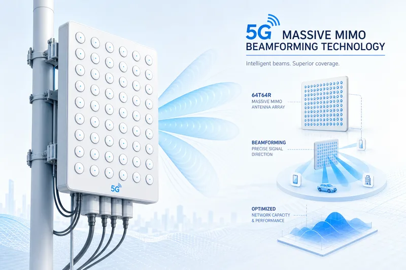
  • 5G CPE Antenna Design Evolution: Beamforming Techniques, Massive MIMO Integration, and Gain Optimization for Next-Generation FWA

    5G CPE Antenna Design Evolution: Beamforming Techniques, Massive MIMO Integration, and Gain Optimization for Next-Generation FWA

    Antenna design has emerged as one of the most critical differentiators in 5G CPE performance, directly impacting signal quality, throughput, coverage range, and user experience in Fixed Wireless Access deployments. As operators push toward multi-gigabit FWA services and dense urban deployments, the antenna subsystem within CPE devices is evolving rapidly—from basic omnidirectional configurations to sophisticated beamforming arrays integrating Massive MIMO principles and AI-driven pattern optimization.

    From Omnidirectional to Beamforming: The Evolution Path

    Early-generation 5G CPE devices, particularly indoor FWA gateways deployed in 2019-2021, typically employed omnidirectional antenna configurations with 4 to 8 elements. While adequate for initial sub-6 GHz deployments in favorable RF conditions, these designs delivered inconsistent performance at cell edges, in high-interference environments, and in buildings with challenging construction materials. Average cell-edge throughput with omnidirectional CPE antennas often fell to 15-25% of peak rates, creating a substantial user experience gap between near-site and edge subscribers.

    The transition to beamforming-capable antenna arrays in 5G CPE devices—typically 8 to 16 elements in current-generation products—has transformed this performance profile. By dynamically steering transmission and reception patterns toward the serving gNodeB, beamforming CPE can deliver 2-4x throughput improvements at cell edges compared with omnidirectional designs, effectively expanding the usable coverage footprint of each base station.

    Massive MIMO Integration in CPE Form Factors

    The integration of Massive MIMO principles into CPE antenna design represents one of the most significant engineering challenges—and opportunities—in current product development. While base station Massive MIMO arrays routinely employ 64 to 256 antenna elements, CPE devices face severe space, power, and thermal constraints that limit practical element counts to 8-16 for indoor units and 16-32 for outdoor CPE installations.

    Advanced antenna module designs are addressing these constraints through several innovations. Multi-layer PCB antenna architectures now enable higher element density within compact enclosures, while integrated antenna-in-package (AiP) solutions for mmWave bands combine antenna elements with RF front-end components in single modules measuring under 30mm per side. For sub-6 GHz bands, metamaterial-inspired antenna designs are achieving wider bandwidth and higher isolation between closely spaced elements than conventional patch or dipole configurations.

    Beamforming Algorithms: Codebook-Based vs. Adaptive Approaches

    The beamforming intelligence embedded in 5G CPE firmware is as important as the physical antenna hardware. Current implementations generally fall into two categories: codebook-based beamforming, which selects from a predefined set of beam patterns based on signal quality measurements, and adaptive beamforming, which dynamically computes optimal beam weights using channel state information.

    Codebook-based approaches offer lower computational complexity and faster beam acquisition, making them suitable for cost-sensitive CPE designs and mobile hotspot applications. Adaptive beamforming, while requiring more processing power and higher-quality channel estimation, delivers superior performance in challenging multipath environments typical of urban and indoor deployments. The most advanced CPE implementations now employ hybrid approaches—using codebook-based beams for initial acquisition and transitioning to adaptive refinement for sustained connections.

    Multi-Beam and Multi-Panel Architectures

    A key advancement in 2025-2026 CPE antenna design is the adoption of multi-beam and multi-panel architectures. Multi-beam CPE devices can simultaneously maintain independent beam patterns toward multiple gNodeBs or toward different propagation paths to the same gNodeB, enabling spatial diversity and multi-TRP (Transmission Reception Point) operation as specified in 3GPP Release 17 and enhanced in Release 18.

    Multi-panel designs distribute antenna elements across multiple faces or surfaces of the CPE enclosure, providing near-omnidirectional coverage while maintaining the gain advantages of directional beamforming. This architecture is particularly valuable for indoor CPE devices where the optimal orientation relative to the serving cell may not be known at installation time. Multi-panel CPE can electronically select and optimize the best panel without requiring physical repositioning.

    mmWave Antenna Challenges and Solutions

    For CPE devices targeting mmWave bands (24-47 GHz), antenna design requirements become substantially more demanding. The shorter wavelengths at these frequencies enable much higher element density but also introduce severe path loss, atmospheric absorption, and blockage sensitivity that must be overcome through antenna gain and beamforming sophistication.

    Current mmWave CPE designs typically employ phased-array antenna modules with 16 to 64 elements per polarization, capable of electronic beam steering across ±60-degree azimuth and elevation ranges. These modules must maintain precise phase calibration across temperature ranges from -40°C to +85°C for outdoor deployments, requiring sophisticated temperature compensation circuitry and calibration firmware. The integration of antenna, beamforming IC, up/down-conversion, and IF processing into single-package AiP modules has been critical to making mmWave CPE commercially viable.

    Gain Optimization Techniques

    Antenna gain optimization in CPE devices involves balancing multiple competing requirements: peak gain for range extension, beam width for angular coverage, side-lobe suppression for interference management, and polarization purity for MIMO spatial multiplexing. Advanced CPE designs employ several techniques to optimize this balance:

    First, tunable impedance matching networks dynamically adjust antenna matching across frequency bands and operating conditions, maintaining optimal VSWR and minimizing mismatch loss. Second, polarization diversity using dual-polarized antenna elements improves MIMO rank and throughput in multipath-rich environments. Third, spatial null-steering algorithms actively suppress interference from adjacent cells by placing antenna pattern nulls in the direction of interfering signals, improving SINR by 3-6 dB in dense deployment scenarios.

    AI-Driven Antenna Optimization

    The integration of machine learning into CPE antenna management represents a frontier capability entering commercial products in 2026. AI-driven antenna systems continuously learn from the RF environment—building profiles of interference patterns, multipath characteristics, and temporal usage patterns—to proactively optimize beam selection, MIMO rank adaptation, and power allocation.

    These systems can predict optimal antenna configurations based on time of day, historical RF conditions, and even weather patterns that affect propagation characteristics. Early field data from operators trialing AI-optimized CPE antenna systems indicate 15-25% improvements in average cell throughput and 30-40% reductions in beam acquisition time compared with conventional algorithmic approaches.

    Procurement Considerations for B2B Buyers

    For operators and enterprises evaluating 5G CPE for large-scale deployments, antenna subsystem specifications deserve careful scrutiny beyond headline throughput numbers. Key evaluation parameters include antenna element count, beamforming type (codebook vs. adaptive), supported beam patterns per polarization, mmWave phased-array module specifications (if applicable), and AI-based optimization capabilities.

    Field validation should include cell-edge throughput testing, interference scenario performance, multi-panel selection behavior, and sustained performance under thermal stress. The antenna subsystem effectively determines the usable coverage radius and subscriber density of FWA deployments, making it a first-order determinant of network economics. Selecting CPE with superior antenna design can reduce required base station density by 15-30%, translating to substantial capital expenditure savings for operators building greenfield FWA networks.

    Honlly Telecom’s 5G CPE product portfolio incorporates advanced beamforming antenna designs across indoor, outdoor, and industrial form factors. Contact the engineering team for detailed antenna subsystem specifications and field performance data.