Category: Blog

Technical guides and best practices

  • The Telecom OEM/ODM Partner Selection Playbook: How ISPs and Operators Can Evaluate CPE Manufacturing Partners for Competitive Product Lines

    The Telecom OEM/ODM Partner Selection Playbook: How ISPs and Operators Can Evaluate CPE Manufacturing Partners for Competitive Product Lines

    For telecom operators, ISPs, and MVNOs seeking to launch branded customer premises equipment (CPE) product lines, selecting an OEM or ODM manufacturing partner is arguably the single most consequential business decision in the product development lifecycle. The right partner delivers competitive hardware, accelerates time-to-market, and protects your brand reputation. The wrong partner creates quality problems, regulatory compliance failures, and costly delays that can damage customer relationships irreparably.

    This playbook provides a structured 14-point evaluation framework designed for telecom procurement teams assessing OEM/ODM CPE manufacturing partners. Each criterion addresses a dimension of manufacturing partnership that directly affects product quality, total cost of ownership, and long-term business viability.

    1. Engineering Competence and R&D Depth

    The foundation of any CPE manufacturing partnership is engineering capability. Evaluate prospective partners across three dimensions:

    In-house design capability: Does the partner employ dedicated RF engineers, antenna designers, embedded systems developers, and industrial designers as full-time staff? A manufacturer that outsources core design work introduces coordination risk and reduces your ability to customize products. Request an organizational chart of the engineering team and verify headcount — a credible CPE ODM should have at least 30-50 engineers covering the full hardware-to-software stack.

    Reference design vs. custom development: Some ODMs are essentially integrators who assemble chipsets from Qualcomm, MediaTek, or UNISOC using vendor-provided reference designs with minimal modification. Others have the capability to customize RF front-end designs, optimize antenna arrays, and develop differentiated firmware features. Understand where each candidate sits on this spectrum. A reference-design integrator may be adequate for basic CPE with short time-to-market requirements, but custom development capability becomes essential for differentiated products in competitive market segments.

    Software and firmware capability: Modern CPE is increasingly software-defined. Your ODM partner must demonstrate competence in OpenWrt-based firmware development, TR-069/TR-369 remote management protocol implementation, OTA update infrastructure, and security hardening. Request examples of firmware customization projects completed for existing clients and verify the partner’s ability to deliver ongoing software maintenance over a 3-5 year product lifecycle.

    2. Certification Track Record

    CPE products must navigate a complex landscape of regulatory and carrier certifications. A manufacturing partner’s existing certification portfolio is a strong indicator of their ability to bring your product to market efficiently.

    Essential certifications to verify:

    • FCC (USA) — Part 15 and Part 96 (CBRS) compliance for 4G/5G devices
    • CE (European Union) — RED Directive 2014/53/EU compliance
    • GCF/PTCRB — Global Certification Forum and PCS Type Certification Review Board for network interoperability
    • Carrier-specific certifications — T-Mobile, AT&T, Verizon, Vodafone, Deutsche Telekom device approval programs
    • Safety certifications — UL, IEC 62368-1, CE LVD
    • Environmental — RoHS, REACH, WEEE compliance

    Ask the ODM for a list of products that have completed each certification category. A partner that has guided multiple products through FCC and CE certification in the last 24 months will navigate the process efficiently. First-time certification projects typically take 4-6 months longer and carry higher risk of rejection or retesting. Factor this time and cost into your evaluation.

    3. Chipset Platform Relationships

    The chipset platform is the most critical component decision in CPE design, and your ODM’s relationship with chipset vendors directly affects pricing, technical support, and roadmap access. Evaluate these relationships:

    Platform diversity: A strong ODM should maintain active relationships with at least two major chipset vendors (Qualcomm, MediaTek, UNISOC, Sequans, ASR Micro). Single-vendor dependency creates supply chain concentration risk and limits your product differentiation options.

    Access tier: Not all ODM-chipset relationships are equal. Premier-tier partners receive earlier access to new chipset platforms, dedicated field application engineer (FAE) support, and preferential pricing. Ask the ODM to characterize their relationship tier with each vendor. Premier-tier relationships translate to faster time-to-market and better technical support when the inevitable integration issues arise.

    Roadmap alignment: Verify that the ODM has visibility into chipset vendor roadmaps for the next 18-24 months. Ask which next-generation platforms (e.g., Qualcomm X80/X85 for 5G-Advanced, MediaTek T830 for Wi-Fi 7-integrated 5G) they are actively developing against.

    4. Manufacturing Facilities and Quality Systems

    Physical factory capability is as important as engineering capability. When evaluating manufacturing partners:

    Factory ownership vs. subcontracting: Some ODMs operate their own SMT (surface-mount technology) lines, assembly facilities, and testing labs. Others are fabless design houses that subcontract manufacturing to third-party EMS (electronics manufacturing services) providers. The ODM-with-factory model offers better quality control and faster issue resolution, but fabless ODMs may offer more flexible capacity scaling. Both models are viable — the key is transparency. A fabless ODM must disclose their EMS partners and demonstrate tight quality management across the subcontractor relationship.

    Quality certifications: Minimum requirements include ISO 9001:2015 (quality management) and ISO 14001 (environmental management). For products targeting automotive or medical verticals, IATF 16949 and ISO 13485 respectively become relevant. Request copies of current certificates, not just claims of compliance.

    Testing infrastructure: In-house RF anechoic chambers, thermal chambers, reliability testing equipment (HALT/HASS), and automated production testing lines are indicators of manufacturing maturity. An ODM that relies entirely on third-party testing labs will have longer development cycles and higher per-project testing costs.

    5. Supply Chain Resilience

    The semiconductor shortages of 2021-2023 demonstrated that supply chain resilience is a competitive advantage, not just a cost consideration. Evaluate:

    Component sourcing strategy: Does the ODM maintain relationships with multiple distributors and authorized channels for critical components (baseband processors, RF front-end modules, memory, power management ICs)? Single-source component dependencies create single points of failure in your product supply.

    Buffer inventory policy: Ask about standard buffer stock levels for long-lead-time components. A responsible ODM should maintain 8-12 weeks of buffer inventory for components with lead times exceeding 26 weeks.

    Geopolitical risk management: For ODMs with manufacturing in China, understand their strategy for managing US-China trade restrictions, particularly around advanced semiconductor access. ODMs with manufacturing facilities in multiple countries (China + Vietnam/India/Malaysia) offer geographic diversification that mitigates single-country trade policy risk.

    6. Intellectual Property Protection

    For operators developing branded CPE with custom industrial design, firmware, or feature sets, IP protection is non-negotiable:

    Contractual IP assignment: The manufacturing agreement must clearly assign IP ownership. Custom industrial design, firmware modifications, and product-specific engineering work you commission should be your IP, not the ODM’s. Review contract language carefully — some ODM standard terms include provisions that grant them broad license rights to your commissioned designs.

    Non-compete and exclusivity: If your product involves proprietary features or unique industrial design, negotiate exclusivity periods (typically 12-24 months) during which the ODM cannot offer substantially similar products to your competitors. Exclusivity comes at a cost but protects your differentiation investment.

    Physical and digital security: Evaluate the ODM’s practices for design file access control, employee NDAs, and customer data segregation. A credible partner should have documented information security policies and be willing to undergo a security audit as part of the qualification process.

    7. Lifecycle Management and Post-Sales Support

    CPE products typically remain in the field for 3-7 years. Post-deployment support quality directly affects your operational costs and customer satisfaction:

    Firmware maintenance commitment: Clarify the ODM’s commitment to security patch delivery, bug fixes, and protocol compatibility updates over the product lifecycle. A minimum commitment should be security patches for 5 years from end-of-sale, with feature updates for at least 3 years.

    RMA and warranty process: Understand the return merchandise authorization (RMA) process, typical failure analysis turnaround time, and root cause reporting quality. A target RMA rate below 2% in the first year and below 1% annually thereafter is a reasonable benchmark for mature CPE products.

    End-of-life management: Plan for product discontinuation from the start. The ODM should commit to last-time-buy notice periods (minimum 6 months), final firmware release delivery, and documentation archival that ensures you can support the product independently if necessary.

    8. Communication and Project Management

    Technical capability is necessary but not sufficient. The ODM’s communication and project management maturity determines whether the partnership will be collaborative or adversarial:

    English-language capability: For international buyers, the ODM’s engineering and project management team must demonstrate working English proficiency. Language barriers introduce specification errors, delay issue resolution, and increase project management overhead. Conduct technical interviews in English during the evaluation process — not just with the sales team but with the engineers who will work on your project.

    Project management methodology: Ask about the ODM’s project management framework (PMP, Agile, or proprietary), milestone tracking tools, and reporting cadence. A structured project management approach with weekly status reports, milestone reviews, and documented change control processes reduces the risk of schedule and budget overruns.

    Time zone and cultural alignment: Factor in communication overhead from time zone differences. An ODM with dedicated account management in or near your time zone significantly reduces friction. Some larger ODMs maintain regional offices in Europe or North America specifically to provide local-time-zone project coordination — this is a meaningful differentiator.

    9. Cost Structure Transparency

    Cost competitiveness matters, but cost structure transparency matters more for long-term partnerships:

    BOM transparency: The ODM should be willing to share an open bill of materials (BOM) with component-level pricing, rather than a black-box unit price. Open BOMs enable you to track component cost movements, identify cost-reduction opportunities, and negotiate fairly when component prices change.

    NRE cost breakdown: Non-recurring engineering (NRE) costs for CPE development typically range from $80,000 to $400,000+ depending on customization depth. The ODM should provide a line-item NRE breakdown covering industrial design, PCB layout, RF tuning, firmware development, tooling, certification testing, and project management. Vague NRE quotes are a red flag.

    Volume pricing curves: Request pricing at multiple volume tiers (1K, 5K, 10K, 50K, 100K+ units). Steep volume discount curves may indicate high fixed costs in the manufacturing process; flat curves suggest the ODM is primarily a design house with outsourced manufacturing. Neither is inherently better — the pricing curve shape should align with your expected volumes.

    10. Existing Customer Portfolio and References

    Past performance is the best predictor of future results:

    Customer type alignment: An ODM that primarily serves consumer electronics brands may struggle with telecom carrier requirements around certification, lifecycle support, and SLAs. Look for partners with demonstrated experience serving telecom operators, ISPs, or enterprise networking brands — not just consumer gadget companies.

    Reference checks: Request permission to contact 2-3 existing customers, ideally in your region and market segment. Key questions for references: How did the ODM handle unexpected technical challenges? Was the project delivered on schedule? How responsive is post-sales support? Would you choose them again for your next product?

    Product teardown: If possible, obtain a production unit from a product the ODM manufactured for an existing customer and perform a teardown analysis. PCB layout quality, solder joint quality, thermal design, and component selection reveal more about manufacturing standards than any sales presentation.

    11. Scalability and Capacity

    Your initial order may be 5,000 units, but a successful product needs to scale to 50,000 or 500,000:

    Production capacity: The ODM should demonstrate capacity to scale from pilot production to volume manufacturing without quality degradation. Ask about monthly SMT line utilization rates — an ODM running at 90%+ utilization has limited capacity headroom for your volume growth.

    Multi-site manufacturing: For higher-volume products, dual-source manufacturing capability (two factories producing the same design) provides business continuity protection. Verify whether the ODM can replicate your production line at a second facility if volumes justify it.

    12. Regulatory and Compliance Expertise

    CPE products are among the most heavily regulated consumer electronics categories. Your ODM must demonstrate proactive regulatory competence:

    Regulatory monitoring: The ODM should maintain awareness of evolving regulations in your target markets — FCC spectrum rule changes, EU Radio Equipment Directive updates, cybersecurity certification requirements (NIST IR 8425 in the US, EN 303 645 in Europe, PSTI Act 2022 in the UK). Ask for examples of how the ODM has adapted products to regulatory changes in the past 24 months.

    Labeling and documentation: Regulatory compliance extends beyond lab testing to product labeling, user documentation, and packaging. The ODM should have experience preparing FCC Supplier’s Declaration of Conformity (SDoC) documentation, EU Declaration of Conformity, and country-specific labeling requirements. Errors in compliance documentation can delay market access by weeks or months.

    13. Innovation and Technology Roadmap

    Today’s CPE specifications won’t be competitive in 2028. Your ODM partner should demonstrate forward-looking technology development:

    R&D investment: Ask about R&D spending as a percentage of revenue (5-10% is typical for competent CPE ODMs) and the number of active R&D projects targeting next-generation technologies — Wi-Fi 7, 5G-Advanced, AI-driven network optimization, eSIM with SGP.32, ambient IoT.

    Technology demonstration capability: A credible ODM should be willing to demonstrate working prototypes or engineering samples of next-generation products, not just PowerPoint roadmaps. Seeing is believing — request a lab visit or video demonstration of their latest platform development.

    14. Cultural Fit and Long-Term Partnership Orientation

    The final criterion is qualitative but critically important: does this ODM operate as a transactional supplier or a strategic partner?

    Problem-solving culture: How does the ODM respond when things go wrong — as they inevitably do in hardware development? Look for partners who communicate problems early with proposed solutions, rather than hiding issues until they become crises. The evaluation process itself reveals cultural patterns: ODMs who are transparent about past project challenges and how they were resolved demonstrate maturity.

    Long-term orientation: CPE product cycles span years, not months. The ideal ODM partner views the relationship as an ongoing collaboration rather than a one-time transaction. Indicators of long-term orientation include proactive technology roadmap sharing, willingness to invest in joint development, and flexible commercial terms that align incentives over the product lifecycle.

    Practical Evaluation Process

    Implementing this 14-point framework requires a structured evaluation process. Recommended approach:

    1. Desktop screening (Weeks 1-2): Evaluate 8-12 candidate ODMs against criteria 1-3 (engineering, certifications, chipset relationships) using publicly available information, website analysis, and initial contact. Narrow to 4-6 candidates.
    2. RFI response (Weeks 3-4): Issue a detailed Request for Information covering criteria 4-12. Score responses against a weighted scorecard. Narrow to 2-3 finalists.
    3. Site visit and audit (Weeks 5-7): Conduct on-site evaluations of finalist facilities. Send a cross-functional team including engineering, quality, supply chain, and program management representatives. Perform reference checks and product teardowns.
    4. Commercial negotiation (Weeks 8-10): Negotiate commercial terms with 1-2 preferred partners, including BOM transparency, NRE costs, volume pricing, IP terms, and exclusivity provisions.
    5. Pilot project (Weeks 11-20): Before committing to full-scale production, execute a pilot project — perhaps a limited customization of an existing platform — to validate the partnership in practice before scaling commitment.

    Conclusion

    Selecting an OEM/ODM CPE manufacturing partner is a decision that reverberates through your product portfolio for years. A structured evaluation process using the 14 criteria outlined above — from engineering depth and certification readiness to IP protection and cultural fit — significantly reduces the risk of selecting an inadequate partner. The upfront investment in thorough evaluation pays dividends in product quality, time-to-market reliability, and long-term partnership value. In the competitive telecom CPE market, your manufacturing partner is not just a supplier — they are a critical component of your competitive strategy.

    Frequently Asked Questions

    What is the difference between OEM and ODM in telecom CPE manufacturing?

    An ODM (Original Design Manufacturer) designs and manufactures products that buyers can brand as their own. The ODM owns the base design and offers customization options. An OEM (Original Equipment Manufacturer) typically produces products based on the buyer’s specifications and designs. In telecom CPE, the ODM model is more common for operators seeking branded devices with moderate customization, while OEM arrangements suit buyers with proprietary technology who need contract manufacturing capacity.

    How much does CPE product development cost with an ODM?

    Non-recurring engineering (NRE) costs for CPE development typically range from $80,000 to $400,000+, depending on the level of customization. A lightly customized reference design with logo and packaging may cost $80,000-$120,000. A fully custom industrial design with modified PCB, custom antenna array, and differentiated firmware typically costs $200,000-$400,000+. These figures exclude certification testing costs, which can add $50,000-$150,000 depending on target markets.

    How long does it take to bring a CPE product to market with an ODM?

    Timeline depends on customization depth. A lightly customized ODM platform product can reach market in 4-6 months (including certification). A moderately customized product with new industrial design and firmware modifications typically requires 8-12 months. A fully custom product with new PCB design, custom antenna, and extensive software development can take 14-18 months. Add 2-4 months if the ODM has no existing certifications in your target markets.

    Should I work with a China-based or non-China ODM for CPE manufacturing?

    China remains the dominant location for CPE ODMs due to ecosystem density, cost competitiveness, and engineering talent availability. However, geopolitical factors (tariffs, trade restrictions) are driving interest in alternative manufacturing locations including Vietnam, India, and Malaysia. The optimal approach for many operators is to work with a China-based ODM that has or is developing multi-country manufacturing capability, providing cost advantages with geographic risk diversification.

    What are the most common mistakes in ODM partner selection?

    The most frequent mistakes include: selecting based on unit price alone without evaluating total cost of ownership; failing to verify certification track record for target markets; inadequate IP protection in manufacturing agreements; choosing an ODM whose primary experience is in consumer electronics rather than carrier-grade equipment; and insufficient technical due diligence (relying on sales presentations rather than engineering audits and product teardowns). Each of these mistakes can delay market entry by 6-12 months or create product quality issues that damage brand reputation.

    Ready to Discuss Your CPE Manufacturing Requirements?

    Honlly Telecom provides comprehensive OEM/ODM manufacturing services for 4G/5G CPE, MiFi, FWA devices, and wireless routers. With ISO 9001-certified manufacturing facilities and a proven track record of carrier-grade product delivery, we help operators and ISPs bring competitive CPE products to market. Contact our team to begin your partner evaluation.

    Contact Honlly Telecom →
  • Outdoor vs Indoor 5G CPE: A Technical Deployment Guide for ISPs Planning Fixed Wireless Access Rollouts

    Outdoor vs Indoor 5G CPE: A Technical Deployment Guide for ISPs Planning Fixed Wireless Access Rollouts

    Every ISP or telecom operator launching 5G Fixed Wireless Access faces the same early architectural question: should we deploy outdoor CPE, indoor CPE, or a mix of both? The answer is never universal — it depends on spectrum band, cell density, building construction materials, target subscriber density, and the operators installation cost model. This guide provides a detailed technical comparison to inform a data-driven deployment strategy.

    The Fundamental Trade-Off

    At the architectural level, the outdoor-vs-indoor CPE decision is a trade-off between RF performance and deployment simplicity:

    • Outdoor CPE: Maximizes signal reception by placing the antenna outside the building envelope, eliminating penetration loss through walls, low-E glass, and reinforced concrete. The trade-off: professional installation is nearly always required, adding $150–$400 per site in labor and mounting hardware.
    • Indoor CPE: Minimizes deployment friction — the subscriber can self-install in minutes by placing the unit near a window. The trade-off: signal loss from building penetration, suboptimal antenna placement, and interference from indoor RF noise sources (Wi-Fi, Bluetooth, microwave ovens).

    The operators achieving the best FWA economics do not choose one or the other — they develop a tiered deployment matrix based on RF planning data.

    Signal Performance: Quantifying the Gap

    Building Penetration Loss

    The RF penalty for indoor placement is significant and highly variable. Measured at 3.5 GHz (n78), typical building penetration losses are:

    • Wood-frame construction with standard glass: 8–12 dB
    • Brick or concrete block with standard glass: 15–22 dB
    • Low-E coated glass (common in modern buildings): 25–35 dB
    • Reinforced concrete with metal-framed windows: 30–40+ dB

    A 20 dB penetration loss effectively reduces the usable cell radius by 40–60%, depending on the propagation model. For an operator deploying on 3.5 GHz with inter-site distances of 800–1200 meters, this is the difference between serving 80% of homes in a cell versus 40%.

    Antenna Gain Comparison

    Modern outdoor CPE units achieve 10–14 dBi of directional gain through phased-array or high-gain panel antenna designs. Indoor CPE units, constrained by form factor and the need for omnidirectional coverage, typically deliver 3–5 dBi per antenna element in a 4×4 MIMO configuration. The net advantage — combining penetration loss avoidance and higher antenna gain — can exceed 20–30 dB in challenging deployment scenarios. That margin frequently determines whether a subscriber receives 100 Mbps or 10 Mbps.

    Installation and Operational Considerations

    Outdoor CPE Installation

    Outdoor CPE requires a trained technician visit for mounting, cable routing, grounding (essential for lightning protection), and alignment toward the serving gNodeB. The process typically takes 60–90 minutes per site. Key installation requirements:

    • Mounting: Wall bracket or pole mount at 3–6 meters above ground. Must be structurally secure and compliant with local building codes.
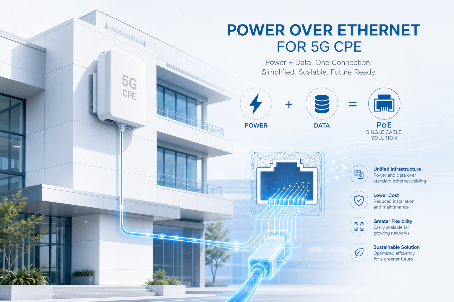
    • Cabling: Outdoor-rated Cat6A or Cat7 Ethernet cable for PoE power and data backhaul to the indoor router/switch. Cable runs of up to 100 meters are possible with 802.3bt (Type 4, 60W) PoE injectors.
    • Grounding: Per IEC 62305 and local electrical codes. The outdoor unit, Ethernet surge protector, and PoE injector must all be properly bonded to the buildings earth ground.
    • Alignment: Using the CPEs onboard signal strength indicator (LED or mobile app RSSI readout), the technician aligns the directional antenna to maximize SINR, not just RSSI. This 5–10 minute step has an outsized impact on long-term throughput stability.

    Indoor CPE Installation

    Indoor CPE is designed for subscriber self-installation. The unit is placed near a window facing the general direction of the cell site, plugged into mains power, and connected to the home network via Ethernet or Wi-Fi. Setup typically takes under 10 minutes. However, self-install success rates vary significantly: operators report 15–25% of indoor self-installs require a technician follow-up due to poor placement, leading to borderline signal quality and higher churn risk.

    Weatherproofing and Environmental Durability

    Outdoor CPE must withstand years of exposure to sun, rain, snow, dust, and temperature extremes. The minimum acceptable ingress protection rating for outdoor CPE is IP67 (dust-tight and protected against temporary immersion). Many carrier-grade units go further with IP68. Key environmental specifications to verify:

    • Operating temperature: –40°C to +60°C (outdoor), 0°C to +45°C (indoor)
    • UV resistance: Enclosure material should be UV-stabilized (UL 746C f1 rating for outdoor use)
    • Wind loading: Specified survival wind speed (typically 200+ km/h for pole-mounted units)
    • Salt fog / corrosion: Per IEC 60068-2-52 for coastal deployments

    Indoor CPE has significantly relaxed environmental requirements, which contributes to its lower unit cost. However, operators should still verify that indoor units meet relevant safety standards (IEC 62368-1) and do not exceed acceptable surface temperatures under sustained load.

    Power over Ethernet (PoE) Architecture

    Outdoor CPE is almost exclusively PoE-powered, eliminating the need for mains power at the mounting location. The current standard is IEEE 802.3bt (PoE++, Type 4) delivering up to 60W at the PSE (Power Sourcing Equipment), with 51W available at the PD (Powered Device) after cable losses. This is sufficient for outdoor CPE with active beamforming arrays, onboard GPS/GNSS, and a companion 2.5GbE switch.

    For operators, the PoE architecture creates an additional deployment consideration: the indoor PoE injector or PoE switch becomes a single point of failure for the entire CPE link. Operators should budget for PoE injector replacements at a rate of 1–2% annually, and consider managed PoE switches with SNMP monitoring for remote power-cycle capability.

    Spectrum Band Considerations

    The outdoor-vs-indoor decision is heavily influenced by the spectrum band used for FWA:

    • Sub-1 GHz (n5, n8, n28): Excellent propagation and building penetration. Indoor CPE performs well in most environments. Outdoor CPE may be unnecessary except in the most challenging locations.
    • Mid-band 3.5 GHz (n77, n78): The most common FWA band globally. Building penetration loss is meaningful — outdoor CPE should be planned for 40–60% of subscribers, varying by building stock.
    • mmWave (n257, n258, n260, n261): Near-zero building penetration. Outdoor CPE with line-of-sight to the gNodeB is effectively mandatory. Indoor mmWave CPE is only viable with specialized window-mounted units incorporating external antenna passthrough.
    • C-band / 4.7 GHz (n79): Similar penetration characteristics to 3.5 GHz but with slightly higher loss. Outdoor CPE penetration in the deployment mix should be 5–10% higher than for 3.5 GHz deployments.

    Total Cost of Ownership Comparison

    Comparing CPE unit prices in isolation is a common procurement mistake. A realistic 36-month TCO comparison for a mid-scale deployment (5,000 subscribers) looks approximately like this:

    Cost Component Outdoor CPE Indoor CPE
    CPE unit cost (volume pricing) $180–$320 $90–$180
    Installation labor + hardware $150–$400 $0 (self-install)
    Annual failure rate 1.5–3% 3–6%
    Truck roll cost per incident $80–$150 $80–$150
    Subscriber churn risk (annual) 8–12% 15–25%
    Estimated 36-month TCO/sub $450–$700 $380–$620

    Counterintuitively, the higher upfront cost of outdoor CPE is often justified by lower churn and fewer support calls. Operators that deploy outdoor CPE in medium-to-weak signal areas while using indoor CPE in strong-signal zones consistently report better unit economics than those using a single CPE type across the entire footprint.

    Recommendations: Building a Tiered Deployment Strategy

    Based on field data from multiple operator deployments, we recommend the following tiered approach:

    1. Strong-signal zones (RSRP > –95 dBm): Indoor CPE with self-install. 30–50% of subscriber base typically falls here in urban/suburban deployments on mid-band spectrum.
    2. Moderate-signal zones (RSRP –95 to –110 dBm): Outdoor CPE with professional install. 35–50% of subscriber base. This is where outdoor CPE delivers the strongest ROI: converting marginal-signal locations into reliable service addresses.
    3. Weak-signal zones (RSRP –110 to –120 dBm): High-gain outdoor CPE with precise alignment, possibly supplemented by external high-gain antennas. 10–15% of subscriber base. These locations should be carefully vetted during the site survey to avoid chronic support issues.
    4. No-service zones (RSRP < –120 dBm): Do not deploy. Prioritize these areas for future small-cell or infill site expansion.

    The exact thresholds should be tuned based on your specific spectrum, gNodeB configuration, and target throughput SLA. The principle, however, is universal: match the CPE type to the RF environment, not the other way around.

    Frequently Asked Questions

    What is the main advantage of outdoor 5G CPE over indoor CPE?

    Outdoor CPE avoids building penetration loss (8–40 dB depending on construction materials) and uses high-gain directional antennas (10–14 dBi vs 3–5 dBi for indoor units). The combined signal advantage can exceed 20–30 dB in challenging locations, which is often the difference between reliable service and no service.

    Can subscribers self-install outdoor 5G CPE?

    While technically possible for some wall-mounted units, professional installation is strongly recommended for outdoor CPE. Proper mounting, grounding (essential for lightning protection), cable routing, and antenna alignment require training and specialized tools. Operators that allow self-install of outdoor CPE typically see higher failure rates and support costs.

    What PoE standard is required for outdoor 5G CPE?

    Most current outdoor 5G CPE requires IEEE 802.3bt (PoE++, Type 4) delivering 60W at the power source. This provides sufficient power for the modem, active antenna array, onboard processing, and a companion Ethernet switch. Verify the specific power budget with your CPE supplier before committing to PoE infrastructure.

    Does outdoor CPE work in extreme weather conditions?

    Carrier-grade outdoor CPE with IP67 or IP68 rating is designed for –40°C to +60°C operating temperature, 200+ km/h wind survival, and salt-fog resistance for coastal deployments. Always verify the environmental specifications against your target deployment geography.

    Which is more cost-effective: outdoor or indoor CPE?

    The answer depends on the RF environment. Indoor CPE has a lower upfront unit cost but higher churn risk and more support calls in marginal-signal areas. Outdoor CPE costs more upfront but delivers lower churn and better throughput stability. Most operators achieve the best economics with a tiered strategy: indoor CPE in strong-signal zones, outdoor CPE in moderate and weak-signal zones.

    Planning a 5G FWA deployment and need expert guidance on CPE selection? Honlly Telecom provides both indoor and outdoor 5G CPE solutions with OEM/ODM customization for operators worldwide. Contact our engineering team for a consultation →

  • How to Evaluate 5G CPE Suppliers: A 15-Point Vendor Assessment Framework for Telecom Operators and ISPs

    How to Evaluate 5G CPE Suppliers: A 15-Point Vendor Assessment Framework for Telecom Operators and ISPs

    For a telecom operator, ISP, or MVNO launching — or scaling — a 5G Fixed Wireless Access service, the CPE device is not a commodity. It is the primary touchpoint with the subscriber, the single largest hardware cost per connection, and the component most likely to generate support calls if it underperforms. A poor CPE decision can erase the margin on an otherwise well-engineered FWA deployment.

    Yet many procurement teams rely on a narrow set of criteria — price per unit, peak throughput on a spec sheet, and perhaps a reference customer or two. This article presents a structured 15-point framework for evaluating 5G CPE suppliers, covering the full lifecycle: silicon selection, software maturity, manufacturing quality, and long-term partnership viability.

    Part 1: Silicon & RF Performance (Points 1–4)

    1. Chipset Platform Generation

    Begin with the modem-RF platform. As of mid-2026, the baseline should be Qualcomm Snapdragon X75/X80 or MediaTek T830. These platforms support 5G-Advanced features including AI-enhanced beamforming, multi-carrier aggregation (up to 4CA on sub-6 GHz), and improved power efficiency. Suppliers still offering X65/X70-based designs are shipping hardware that is two generations behind — the performance gap in real-world deployments is measurable and growing.

    Evaluation action: Request the exact modem model and firmware revision. Verify it against the chipset vendors current product roadmap. Ask whether the supplier has committed volumes with the chipset vendor — this affects both pricing and long-term availability.

    2. Carrier Aggregation Combinations

    A 5G CPE spec sheet may list “3CA” or “4CA” support, but the specific band combinations matter enormously. An operator deploying on n78 (3.5 GHz) with n28 (700 MHz) for uplink coverage needs the CPE to support that exact combination, not a theoretical maximum. Request the suppliers certified CA combination table — preferably with GCF/PTCRB validation — and cross-reference it against your planned spectrum holdings.

    3. Antenna Architecture and Gain

    The antenna system — not the modem — often limits real-world CPE performance. Evaluate:

    • Indoor units: 4×4 MIMO with at least 3–4 dBi per element across operating bands. Look for polarization diversity, not just spatial diversity.
    • Outdoor units: Directional or phased-array design delivering 10–14 dBi gain across the primary band. Ask for 3D radiation pattern plots, not just single-number gain figures.
    • Self-install vs. professional install: If targeting the consumer self-install market, the antenna must be forgiving of suboptimal placement. Request chamber test data showing performance at ±30° misalignment from boresight.

    4. 5G-Advanced Readiness

    CPE deployed in 2026 will likely remain in the field for 3–5 years. During that time, operator networks will activate 3GPP Release 18 features including AI/ML-based CSI compression, multi-TRP coordination, and enhanced positioning. Confirm whether the suppliers CPE can support these features via field-upgradable firmware, or whether they require a hardware swap. Suppliers that have demonstrated OTA firmware upgrades in production networks should score higher.

    Part 2: Software, Management & Interoperability (Points 5–8)

    5. TR-369 USP Support

    The Broadband Forums User Services Platform (USP, TR-369) is the successor to TR-069 and is now the expected device management protocol for greenfield FWA deployments. A CPE without a mature USP agent creates operational friction: manual provisioning, reactive troubleshooting, and inability to push configuration changes or firmware updates at scale.

    Evaluation action: Ask for the suppliers USP Agent conformance test results (TP-469). Request a live demo of remote provisioning, parameter get/set, firmware upgrade, and factory reset via USP. Confirm support for the Device:2 data model with WiFi. and Cellular. objects fully populated.

    6. Zero-Touch Provisioning (ZTP)

    Can the CPE be dispatched directly from the manufacturer to the end subscriber without intermediate staging? ZTP requires the device to bootstrap securely, contact the operators ACS (Auto Configuration Server), and download its configuration automatically. Evaluate the suppliers ZTP flow end to end, including secure credential injection at the factory (SCEP/EST-based certificate enrollment, not hardcoded passwords).

    7. Interoperability Testing History

    A CPE that works perfectly in the lab can fail mysteriously on a live network due to subtle RAN implementation differences between Ericsson, Nokia, Samsung, and Huawei gNodeBs. The supplier should provide IOT (Interoperability Testing) reports from at least two major RAN vendors, ideally including results from your specific network equipment vendor.

    8. IPv6 and Dual-Stack Readiness

    Many enterprise and government RFPs now require full IPv6 support. The CPE must handle IPv6-only WAN (464XLAT/CLAT), dual-stack, and IPv4aaS transparently. Confirm DHCPv6-PD (Prefix Delegation) for downstream LAN, SLAAC, and DNS64/NAT64 support.

    Part 3: Hardware Quality & Manufacturing (Points 9–12)

    9. Thermal Design Validation

    5G CPE, especially outdoor units in direct sunlight, must dissipate 15–25W of thermal load without throttling. Request the suppliers thermal chamber test report showing sustained throughput at 55°C and 65°C ambient. Look for evidence of heatsink design, airflow modeling (CFD simulation), and component derating analysis. A CPE that throttles at high temperature will generate disproportionate support calls in warm-climate deployments.

    10. Manufacturing Capacity and Quality Certifications

    Visit the factory if possible; if not, request documentation. Key certifications: ISO 9001 (quality management), ISO 14001 (environmental management), and ideally IATF 16949 if the supplier also serves automotive — this indicates a high maturity level in manufacturing process control. Ask about monthly production capacity, typical lead times, and surge capacity (can they double output within 60 days?).

    11. Regulatory Compliance Portfolio

    CPE must carry regional certifications: FCC (US), CE (EU), UKCA (UK), ANATEL (Brazil), IC (Canada), RCM (Australia), and others depending on target markets. A supplier that already holds certifications for your target regions can save 8–16 weeks and significant cost versus pursuing new certifications. Request a compliance matrix showing exactly which SKUs hold which certifications.

    12. Supply Chain Transparency

    Post-2023, supply chain resilience is a board-level concern. The CPE supplier should disclose their bill of materials (BOM) risk assessment: which components are single-source, which have qualified second sources, and what alternative components are pre-validated. Suppliers with deep relationships with Qualcomm and MediaTek, and with strategic buffer stock agreements, should be preferred.

    Part 4: Commercial & Partnership (Points 13–15)

    13. Total Cost of Ownership, Not Unit Price

    A low unit price can be deceptive. Calculate TCO over a 36-month lifecycle including: CPE unit cost, shipping and logistics, installation labor (outdoor CPE installs cost 3–5× more than indoor), predicted failure rate × replacement cost, firmware maintenance fees, and technical support burden. A CPE with a 1% lower annual failure rate can save hundreds of thousands of dollars at scale, even at a higher unit price.

    14. OEM/ODM Flexibility

    Does the supplier offer white-label and custom branding options? Can they customize the industrial design, packaging, firmware UI, and default configuration for your operator brand? For larger deployments, operator-specific firmware builds with custom TR-069/USP data model extensions, branded WebUI, and pre-loaded APN settings reduce deployment friction significantly.

    15. Long-Term Roadmap Alignment

    The best CPE supplier relationship is a partnership, not a transaction. Evaluate whether the supplier has a published product roadmap covering the next 24–36 months. Does it align with your network evolution plans — for example, do they have a Wi-Fi 8 CPE on the roadmap, or a 3GPP Release 19-capable device planned? A supplier investing in continuous R&D is more likely to remain a viable partner through the deployment lifecycle.

    Scorecard Approach

    We recommend scoring each of the 15 points on a 0–3 scale (0 = unacceptable, 1 = below average, 2 = meets requirements, 3 = exceeds requirements), then weighting according to your specific deployment priorities. A minimum threshold of 30 out of 45 (weighted) is a reasonable starting filter before proceeding to lab testing and field trials.

    The operators that invest disciplined evaluation effort upfront consistently report lower churn, fewer support calls, and better subscriber NPS than those that select CPE primarily on price. In a market moving toward 100 million FWA connections, CPE quality is not a cost center — it is a competitive moat.

    Frequently Asked Questions

    Which chipset should a 5G CPE use in 2026?

    For new FWA deployments, Qualcomm Snapdragon X75/X80 and MediaTek T830 are the recommended baseline platforms. These support 5G-Advanced features including AI-enhanced beamforming, 4CA carrier aggregation, and improved power efficiency. Avoid X65/X70-based designs for new rollouts.

    What is TR-369 USP and why is it critical for 5G CPE?

    TR-369 (User Services Platform) is the Broadband Forums modern device management protocol, replacing the aging TR-069. It enables operators to remotely provision, monitor, troubleshoot, and upgrade CPE at scale with a secure, efficient architecture. For FWA deployments spanning thousands or tens of thousands of units, a mature USP agent is operationally essential.

    How much does 5G CPE cost for operators?

    Indoor 5G CPE typically ranges from $80–$200 per unit in operator volumes (1,000+ units), while outdoor CPE ranges from $150–$350 depending on antenna complexity and enclosure requirements. However, total cost of ownership — including installation, support, failure replacement, and firmware maintenance — should be the primary metric, not unit price alone.

    What certifications should a 5G CPE have for global deployment?

    Essential certifications include FCC (US), CE (EU), UKCA (UK), IC (Canada), ANATEL (Brazil), and RCM (Australia/NZ). Additional certifications may be required for specific markets — suppliers with a broad existing certification portfolio can reduce time-to-market by 8–16 weeks.

    Should operators choose outdoor or indoor CPE for FWA?

    Most successful FWA deployments use a mix: outdoor CPE with high-gain directional antennas in cell-edge and weak-signal locations, indoor CPE with omnidirectional antennas in strong-signal urban and suburban areas. The decision should be based on RF planning data, not a one-size-fits-all approach.

    Evaluating 5G CPE suppliers for your next network deployment? Honlly Telecom offers carrier-grade 5G CPE, OEM/ODM manufacturing, and customized solutions for ISPs and operators worldwide. Speak with our solutions team →

  • OEM, ODM, and JDM Manufacturing Models for CPE: What Telecom Buyers Should Know Before Partnering with a Factory

    OEM, ODM, and JDM Manufacturing Models for CPE: What Telecom Buyers Should Know Before Partnering with a Factory

    The global telecom CPE supply chain is built on three distinct manufacturing partnership models — OEM, ODM, and JDM. Yet many telecom buyers enter factory negotiations without a clear understanding of how these models differ, what they imply for intellectual property, lead times, unit economics, and ongoing product support. This guide clarifies each model and provides a framework for selecting the right approach.

    The Three Models Defined

    OEM (Original Equipment Manufacturing)

    In an OEM engagement, the buyer owns the product design, specifications, and intellectual property. The factory serves as a build-to-print manufacturing partner: it procures components per the buyer’s approved BOM, assembles the product according to the buyer’s engineering documentation, and executes quality control against the buyer’s acceptance criteria. The buyer retains full control over design, component selection, firmware, and branding.

    Best for: Operators and enterprises with existing hardware engineering teams and proven reference designs who need capacity or cost optimization in manufacturing.

    Typical MOQ: 10,000–50,000 units, depending on BOM complexity and component lead times.

    Lead time: 16–24 weeks from PO to first shipment, assuming design is frozen and tooling is complete.

    ODM (Original Design Manufacturing)

    In an ODM model, the factory develops, designs, and manufactures a product that is sold under the buyer’s brand. The ODM owns the core hardware design, software platform, and sourcing relationships. The buyer selects from the ODM’s existing product portfolio (or commissions minor modifications) and applies branding, packaging, and go-to-market execution. This is the most common model in the CPE industry for operators seeking quick time-to-market with proven hardware.

    Best for: Operators, MVNOs, and distributors who want to launch branded CPE products without investing in hardware R&D. Ideal for 4G MiFi, 5G FWA CPE, and indoor/outdoor routers.

    Typical MOQ: 500–5,000 units for standard SKUs; 5,000+ for hardware modifications.

    Lead time: 4–8 weeks for standard white-label products; 12–20 weeks with hardware modifications.

    JDM (Joint Design Manufacturing)

    JDM represents a collaborative middle ground. The buyer and manufacturer jointly define the product specification, share design responsibilities, and co-develop the solution. The buyer typically contributes system architecture, industrial design direction, and user experience requirements, while the manufacturer contributes hardware engineering, RF design, sourcing, and production engineering. IP ownership is negotiated and shared per the JDM agreement.

    Best for: Operators and technology companies with domain expertise and specific performance requirements but without a full in-house hardware engineering team. Common for carrier-grade CPE, specialized outdoor units, and 5G mmWave devices.

    Typical MOQ: 5,000–20,000 units, reflecting the shared investment in development.

    Lead time: 20–36 weeks from joint specification freeze to first shipment.

    Decision Framework: Choosing Your Model

    Factor OEM ODM JDM
    IP Ownership Buyer owns all ODM owns design; buyer owns brand Shared per agreement
    Time to Market Longest (16–24 weeks) Fastest (4–8 weeks) Medium (20–36 weeks)
    NRE Cost Highest (tooling, line setup) Lowest (branding only) Moderate (shared cost)
    Per-Unit Cost Lowest at scale Standard ODM pricing Competitive at volume
    Design Control Full buyer control Limited (brand-level) Shared (collaborative)
    Best For Own design, need scale Quick launch, proven HW Custom product, shared R&D

    How to Evaluate an ODM/JDM Partner: Red Flags to Watch

    Selecting the right manufacturing partner is as important as choosing the model itself. Based on Honlly’s experience working with operators across 30+ countries, here are the red flags procurement teams should watch for:

    1. Undocumented design ownership: If the ODM cannot produce a clear bill of materials with component source traceability and design version history, walk away. This indicates poor engineering discipline that will manifest as quality problems downstream.
    2. No in-house RF lab: CPE is fundamentally an RF product. A manufacturer without an anechoic chamber, vector network analyzer, and conducted/radiated test capability cannot properly validate antenna performance, TRP/TIS, or regulatory compliance.
    3. Opaque firmware roadmap: Ask for the last 12 months of firmware release notes. A manufacturer with irregular or undocumented firmware updates will be a liability when security vulnerabilities or carrier certification updates are required.
    4. Unclear certification ownership: Confirm who pays for and maintains certifications (FCC, CE, GCF, PTCRB). If a certification lapses, who bears the recertification cost? These terms must be explicit in the manufacturing agreement.
    5. No regional support infrastructure: A factory that cannot provide local-language technical support, RMA handling, and spare parts logistics in your target market will create operational headaches that erode any per-unit cost advantage.

    The Honlly Approach: Flexible ODM with JDM Capability

    Honlly Telecom operates primarily as an ODM partner for 4G/5G CPE, MiFi, and FWA devices, but maintains in-house hardware and RF engineering teams that enable JDM-style collaboration for operators with specific performance or form-factor requirements. Our Shenzhen-based engineering center includes a full anechoic chamber, thermal testing lab, and software QA infrastructure that supports end-to-end product development from concept through mass production.

    For operators evaluating manufacturing partnerships, we recommend starting with an ODM engagement on a proven platform to validate quality, delivery reliability, and support responsiveness. As the relationship matures, JDM collaboration becomes a natural next step for custom product development.

    FAQ

    What is the difference between OEM and ODM in CPE manufacturing?

    In OEM, the buyer owns the product design and the factory builds to the buyer’s specifications. In ODM, the factory owns the design and the buyer brands and sells the product. ODM is the faster, lower-cost path to market for operators without in-house hardware engineering.

    What is JDM manufacturing?

    JDM (Joint Design Manufacturing) is a collaborative model where buyer and manufacturer jointly define specifications and share design responsibilities. It combines the buyer’s market and UX expertise with the manufacturer’s hardware engineering capabilities.

    What MOQ should I expect for ODM CPE products?

    Standard white-label ODM CPE typically requires 500–5,000 units minimum order quantity. Customized hardware modifications raise the MOQ to 5,000+ units. OEM builds generally require higher MOQs (10,000+).

    How long does it take to bring an ODM CPE product to market?

    Standard ODM white-label CPE can ship in 4–8 weeks. Products requiring hardware modifications typically take 12–20 weeks. JDM development adds 20–36 weeks from specification freeze.

    Ready to Discuss Your CPE Manufacturing Requirements?

    Whether you need standard ODM white-label products or joint development of a custom CPE solution, Honlly Telecom’s engineering team is ready to support your project from concept to mass production.

    Schedule a Consultation →

  • The Complete 4G MiFi Buyer’s Checklist: 12 Features Every Telecom Operator Should Verify Before Procurement

    The Complete 4G MiFi Buyer’s Checklist: 12 Features Every Telecom Operator Should Verify Before Procurement

    4G MiFi devices remain the workhorse of enterprise mobile connectivity in 2026. Despite the rapid expansion of 5G networks, LTE-based mobile hotspots continue to serve the vast majority of field workforce deployments, fleet connectivity applications, and temporary site setups across global markets. The reasons are straightforward: mature coverage, predictable performance, lower device and service costs, and a deep ecosystem of certified hardware.

    For telecom operators, ISPs, and enterprise procurement teams, selecting the right 4G MiFi device is not a trivial exercise. The market offers dozens of models from established ODMs and emerging manufacturers, each with different feature sets, frequency band support, and management capabilities. A poorly specified device can lead to increased support tickets, early hardware replacement cycles, and frustrated end users.

    This checklist identifies the 12 features that procurement professionals should verify before signing a purchase order — organized by category for systematic evaluation.

    Category 1: Radio Frequency and Network Performance

    1. LTE Category and Carrier Aggregation Support

    The LTE category defines the device’s theoretical peak throughput. For enterprise MiFi, Category 6 (300 Mbps down / 50 Mbps up) is the practical minimum in 2026. Category 12 (600/100 Mbps) or Category 16 (1 Gbps/150 Mbps) devices offer meaningful real-world improvements through 3x carrier aggregation and 256QAM, particularly in congested urban environments. Verify that the vendor specifies the supported CA band combinations relevant to your deployment region.

    2. Frequency Band Coverage

    At minimum, the device should support B1/B3/B5/B7/B8/B20/B28 for EMEA deployments, or B2/B4/B5/B12/B13/B14/B66/B71 for North America. For operators serving multiple regions, pan-regional SKUs with 12+ bands reduce inventory fragmentation. Always request a complete band list with 2CA and 3CA combination tables from the vendor.

    3. MIMO and Antenna Configuration

    2×2 MIMO is table stakes. Devices with external antenna ports (TS-9 or SMA) provide substantial throughput gains in fringe-coverage areas when paired with external LTE antennas. For fleet and vehicle-mounted applications, this feature is non-negotiable.

    Category 2: Connectivity and Concurrent Users

    4. Wi-Fi Specifications

    Dual-band concurrent Wi-Fi (2.4 GHz + 5 GHz) with 802.11ac Wave 2 is the minimum standard. For higher-density deployments, seek 802.11ax (Wi-Fi 6) support which provides OFDMA-based efficiency gains when serving multiple simultaneous clients. Verify the maximum Wi-Fi connected client count — 16+ users is expected for enterprise MiFi.

    5. Ethernet and USB Tethering

    Many enterprise use cases require wired connectivity. A Gigabit Ethernet port (RJ-45) enables the MiFi to function as a primary WAN link for a small router or firewall. USB 3.0 tethering support with RNDIS/ECM driver compatibility ensures the device can connect to Linux-based edge gateways and industrial controllers.

    Category 3: Power and Physical Design

    6. Battery Capacity and Runtime

    For field workforce devices, a minimum 3,000 mAh removable battery delivering 8+ hours of active use is expected. For always-on applications, devices supporting battery-bypass operation (powered via USB or DC while battery is removed) prevent battery swelling common in 24/7 plugged-in deployments.

    7. Enclosure Durability and Environmental Rating

    For indoor use, standard plastic enclosures suffice. For outdoor, industrial, or vehicle-mounted deployments, look for IP54 or higher ingress protection, operating temperature range of -10°C to +55°C, and vibration resistance compliance (MIL-STD-810G or equivalent).

    Category 4: Device Management and Security

    8. Remote Device Management Protocol Support

    TR-069 (CWMP) remains the most widely deployed CPE management protocol; TR-369 (USP) is the emerging standard. Verify which protocol the device supports and confirm interoperability with your ACS platform (GenieACS, AVSystem, Friendly, etc.). At minimum, the device should support remote firmware upgrade, configuration push, parameter monitoring, and reboot via the management protocol.

    9. VPN and Security Features

    Enterprise MiFi devices should support IPsec and L2TP/IPsec VPN passthrough, WPA3-Personal Wi-Fi security, and a configurable firewall with ACL support. For regulated industries, verify FIPS 140-2 or equivalent cryptographic module validation.

    10. SIM Management

    eSIM (eUICC) support is increasingly important for operators managing large fleets across multiple MNO profiles. Physical SIM slot type (2FF/3FF/4FF) compatibility and dual-SIM capability for failover scenarios should also be specified in the RFP.

    Category 5: Software and Customization

    11. Branding and UI Customization

    If the device will be sold under your operator brand, confirm that the ODM supports complete white-labeling: custom boot logo, Web UI branding (logo, color scheme, SSID prefix), packaging design, and firmware default configuration pre-loading. Ask for the MOQ threshold for each customization tier.

    12. Regulatory Certification Portfolio

    Verify that the device carries current certifications for your target markets: CE (EU), FCC (US), ISED (Canada), RCM (Australia), NCC (Taiwan), and any other market-specific requirements. For operators, GCF and PTCRB certification streamline network approval processes.

    Procurement Evaluation Matrix

    When evaluating multiple vendors, use a weighted scoring matrix. Recommended weights: RF performance and band coverage (25%), device management capabilities (20%), durability and power (15%), security features (15%), customization and branding (15%), and certifications (10%). This structured approach prevents procurement teams from being swayed by a single standout feature while overlooking critical gaps.

    FAQ

    What is the minimum LTE category for an enterprise-grade 4G MiFi?

    Category 6 (300 Mbps down) is the practical minimum in 2026. Category 12 or higher provides meaningful real-world improvements through 3x carrier aggregation and is recommended for deployments in congested urban environments.

    Does a 4G MiFi need external antenna ports?

    For fleet, vehicle-mounted, and fringe-coverage applications, external antenna ports (TS-9 or SMA) are strongly recommended. They provide 3–6 dB signal improvement when paired with external LTE antennas, which directly translates to higher throughput and fewer dropped connections.

    Should I choose a 4G MiFi with eSIM support?

    If you manage a fleet of devices across multiple MNOs or plan to change carrier profiles remotely, eSIM (eUICC) support is highly valuable. It eliminates physical SIM swaps and enables over-the-air profile provisioning via GSMA-compliant RSP platforms.

    What device management protocols should a 4G MiFi support?

    TR-069 (CWMP) remains essential for compatibility with existing ACS platforms. TR-369 (USP) is the future direction and should be considered for new deployments. Both protocols enable remote configuration, firmware updates, and monitoring at scale.

    Need a Custom 4G MiFi Solution for Your Network?

    Honlly Telecom designs and manufactures 4G MiFi devices to your exact specifications. From band configuration to branding, we deliver turnkey solutions for operators and enterprises worldwide.

    Request a Quote →

  • mmWave vs Sub-6 GHz 5G CPE: A Practical Deployment Comparison for Fixed Wireless Access

    mmWave vs Sub-6 GHz 5G CPE: A Practical Deployment Comparison for Fixed Wireless Access

    One of the most consequential decisions in a 5G Fixed Wireless Access (FWA) deployment is the choice of radio spectrum specifically, whether to deploy in millimeter wave (mmWave) bands above 24 GHz or in sub-6 GHz bands below 6 GHz. Each spectrum type imposes fundamentally different requirements on the CPE hardware, the installation process, and the network planning methodology. This article provides a structured comparison to help ISPs, system integrators, and telecom operators make informed CPE procurement decisions.

    The Physics of the Two Spectrum Worlds

    Sub-6 GHz 5G operates in bands such as n1 (2100 MHz), n3 (1800 MHz), n7 (2600 MHz), n28 (700 MHz), and n78 (3500 MHz). These frequencies propagate well through walls, foliage, and moderate obstacles, with typical outdoor-to-indoor penetration loss of 10-18 dB. A sub-6 GHz CPE installed indoors near a window can often achieve usable signal quality without external antenna mounting. Range is measured in kilometers: a well-engineered n78 deployment with 4×4 MIMO and 256QAM can serve customers 3-5 km from the cell site in suburban environments.

    mmWave 5G operates in bands such as n257 (28 GHz), n258 (26 GHz), n260 (39 GHz), and n261 (28 GHz, US). At these frequencies, propagation is fundamentally different. Free-space path loss is 20-30 dB higher than sub-6 GHz at equivalent distance, outdoor-to-indoor penetration through modern energy-efficient windows can exceed 25-30 dB of loss, and even foliage or heavy rain can attenuate the signal. A single tree between the cell site and the CPE can reduce mmWave throughput by 50% or more. The practical range for mmWave FWA is typically 300-800 meters in urban deployments and requires near-line-of-sight conditions.

    However, mmWave compensates for propagation challenges with raw bandwidth. A single n257 carrier in the 28 GHz band can be up to 400 MHz wide four times the maximum 100 MHz carrier width available in n78 sub-6 GHz. This translates directly into multi-gigabit peak throughput: commercial mmWave CPE devices routinely deliver 2-4 Gbps downlink under good signal conditions, compared to 500 Mbps to 1.5 Gbps for sub-6 GHz CPE in typical deployments.

    CPE Hardware: Different Requirements, Different Designs

    The physical design of mmWave CPE differs substantially from sub-6 GHz CPE due to the antenna requirements. mmWave devices use phased-array antenna modules typically 16 to 64 antenna elements arranged in a flat panel to achieve beamforming gain that compensates for path loss. These modules are physically larger than sub-6 GHz antennas and must be mounted with a clear, unobstructed view of the serving cell, which almost always requires outdoor installation.

    Outdoor mmWave CPE, such as Honlly Telecom HL-880U series, integrates the phased-array antenna, modem, and networking electronics into a single IP67-rated enclosure designed for pole, wall, or rooftop mounting. Power is delivered via Power over Ethernet (PoE), and the indoor unit connects through a single Ethernet cable. This architecture eliminates the RF cable loss that would be incurred by a split indoor-outdoor design a critical advantage at mmWave frequencies where every decibel of loss matters.

    Sub-6 GHz CPE offers more deployment flexibility. Indoor desktop CPE with integrated antennas can serve a significant portion of the coverage footprint, especially in the lower bands (n28, n3, n1) where building penetration is adequate. For edge-of-coverage or rural deployments, outdoor sub-6 GHz CPE with high-gain directional antennas (8-12 dBi) can extend range and improve signal quality, trading some installation simplicity for better performance.

    Deployment Scenarios: When to Choose Which

    Urban and dense suburban FWA. In neighborhoods where cell sites are spaced 500-800 meters apart and subscribers are concentrated, mmWave FWA delivers fiber-like speeds that can compete directly with cable broadband. The CPE cost is higher (typically 2-3x a comparable sub-6 GHz device), but the capacity advantage per sector makes it viable where subscriber density justifies the investment. Operators such as Verizon have deployed mmWave FWA to over 40 million households in the US using this model.

    Suburban and rural broadband. Where cell site spacing exceeds 1-2 km, sub-6 GHz FWA is the practical choice. The longer range and better non-line-of-sight (NLOS) performance of sub-6 GHz bands particularly when combining low-band carriers (n28, 700 MHz) for coverage with mid-band carriers (n78, 3500 MHz) for capacity via carrier aggregation provides a more cost-effective solution for lower-density areas. A single n78 cell site can cover an area 10-25 times larger than a mmWave site, dramatically reducing infrastructure cost per subscriber.

    Enterprise and industrial fixed wireless. For enterprise customers requiring symmetric multi-gigabit throughput think video production studios, data center interconnects, or campus backbone links mmWave is the preferred option when line-of-sight conditions exist. For enterprise applications where reliability and availability outweigh peak throughput (e.g., retail point-of-sale, branch office connectivity, backup WAN), sub-6 GHz CPE with dual-SIM failover provides a more resilient solution.

    Cost Comparison: Total Cost of Ownership

    The per-device cost comparison tells only part of the story. A comprehensive TCO analysis for FWA deployments should account for multiple factors:

    • CPE unit cost: mmWave CPE typically ranges from USD 300-600 per unit, compared to USD 120-350 for sub-6 GHz CPE
    • Installation cost: mmWave requires professional outdoor mounting at USD 150-400 per site, while sub-6 GHz can often be self-installed indoors (USD 50-200 for outdoor installs)
    • Site survey requirements: Essential for mmWave line-of-sight verification; recommended for edge-of-coverage sub-6 GHz only
    • Cell site density: mmWave requires 300-800m spacing with more sites needed; sub-6 GHz works with 1-5 km spacing
    • Capacity per sector: mmWave delivers 4-8 Gbps supporting high subscriber density; sub-6 GHz delivers 1-3 Gbps for moderate density

    Decision Framework: Five Questions to Guide Your Choice

    1. What is the target subscriber density? High-density urban areas with more than 500 potential subscribers per square kilometer favor mmWave. Rural areas with fewer than 50 subscribers per square kilometer almost always favor sub-6 GHz.
    2. What throughput SLA are you offering? If the service tier requires more than 500 Mbps downlink consistently, mmWave becomes the primary candidate. For service tiers up to 100-300 Mbps, sub-6 GHz is typically sufficient.
    3. Can you support professional truck-roll installations? If the business model relies on self-install, sub-6 GHz indoor CPE is the only practical option. mmWave FWA requires professional installation for antenna alignment and line-of-sight verification.
    4. What spectrum do you have access to? This is often the decisive factor. Operators with substantial mmWave holdings can deploy mmWave FWA. Operators with primarily sub-6 GHz spectrum will naturally deploy sub-6 GHz FWA, potentially augmenting with mmWave in high-demand urban hotspots.
    5. Is the deployment indoors or outdoors? Indoor CPE almost always operates in sub-6 GHz bands, as mmWave building penetration loss is prohibitive. Outdoor CPE can support either spectrum type, with the choice driven by the factors above.

    The Hybrid Future: Multi-Band CPE

    An emerging category of CPE combines sub-6 GHz and mmWave radios in a single device, using sub-6 GHz as an anchor for coverage and reliability while aggregating mmWave for capacity bursts. Qualcomm Snapdragon X80 modem-RF platform, announced in early 2026, supports concurrent sub-6 GHz + mmWave aggregation with intelligent traffic steering. While these multi-band devices currently command a premium, they represent a strategic option for operators planning long-term FWA infrastructure that can adapt to evolving spectrum availability and subscriber demand.

    Frequently Asked Questions

    Q: Can a single CPE support both mmWave and sub-6 GHz?
    A: Yes, multi-band CPE devices with dual radio chains can support both spectrum types, though they are more expensive than single-band devices. These are increasingly common in the premium CPE segment and are well-suited for operators who want deployment flexibility across diverse coverage footprints.

    Q: Does weather affect mmWave CPE performance?
    A: Yes. Heavy rain causes attenuation of 5-10 dB/km at 28 GHz, snow accumulation on antenna enclosures, and even dense fog can reduce mmWave signal quality. Outdoor mmWave CPE should be specified with adequate link budget margin (typically 10-15 dB above the minimum usable signal) to maintain service during adverse weather conditions.

    Q: Is sub-6 GHz 5G fast enough compared to mmWave?
    A: For the vast majority of residential and small business FWA use cases, sub-6 GHz 5G delivering 100-500 Mbps is more than adequate supporting 4K streaming, video conferencing, cloud applications, and multiple simultaneous users. mmWave becomes relevant when service tiers exceed 500 Mbps or when very high per-sector capacity is needed to serve dense subscriber concentrations.


    Looking for CPE solutions optimized for your spectrum strategy? Honlly Telecom supplies both sub-6 GHz and mmWave-ready CPE devices for fixed wireless access deployments worldwide, with carrier-grade TR-369 management and flexible OEM customization options. Contact our team to discuss your requirements.

  • Carrier Aggregation in 4G and 5G CPE: A Technical Buyer’s Guide to Real-World Throughput Performance

    Carrier Aggregation in 4G and 5G CPE: A Technical Buyer’s Guide to Real-World Throughput Performance

    When evaluating 4G and 5G CPE for procurement, one specification consistently correlates with real-world performance yet is often misunderstood by buyers: carrier aggregation (CA). A device CA capability directly determines peak throughput, cell-edge performance, and spectrum efficiency three metrics that translate into subscriber satisfaction and churn reduction for service providers. This guide provides a technical framework for evaluating CA in CPE, with practical criteria that procurement teams, network planners, and system integrators can apply when comparing products.

    What Carrier Aggregation Actually Does

    Carrier aggregation combines multiple component carriers discrete blocks of licensed spectrum into a single logical data pipe. In LTE-Advanced, CA was introduced in 3GPP Release 10 and initially supported aggregation of up to five component carriers (5CA), each up to 20 MHz wide. In 5G NR, the concept expands significantly: a single component carrier can span up to 100 MHz in sub-6 GHz (Frequency Range 1) or up to 400 MHz in mmWave (Frequency Range 2), and aggregation can combine carriers across both frequency ranges.

    The throughput math is straightforward in principle. Aggregate two 20 MHz LTE carriers with 256QAM modulation and 4×4 MIMO, and you approach a theoretical peak of 400 Mbps downlink double what a single carrier can deliver. In practice, field conditions, backhaul constraints, and interference reduce these numbers, which is why understanding real-world CA behavior is essential for procurement decisions.

    CA Class Ratings: What the Numbers Mean

    Datasheets commonly list CA capability in shorthand that buyers should learn to decode:

    • LTE Cat 4: No carrier aggregation. Single carrier, up to 150 Mbps DL. Suitable for basic M2M and low-bandwidth IoT applications not recommended for residential or enterprise broadband CPE.
    • LTE Cat 6 / Cat 7: 2CA (two-carrier aggregation). Up to 300 Mbps DL. The baseline for acceptable fixed wireless access (FWA) in suburban and rural deployments where spectrum holdings are limited to two bands.
    • LTE Cat 12 / Cat 13: 3CA, up to 600 Mbps DL. A solid mid-tier option that aggregates three carriers typically combining low-band for coverage with mid-band for capacity.
    • LTE Cat 16 / Cat 18: 3CA to 5CA, up to 1.2 Gbps DL. These devices support 4×4 MIMO on multiple carriers and 256QAM, making them suitable for high-demand FWA services where LTE spectrum depth is available.
    • LTE Cat 20: Up to 5CA, 2 Gbps DL theoretical. The highest LTE CA tier, often deployed in markets where 5G NR rollout is still underway but capacity demand is high.

    For 5G NR CPE, CA capability descriptions are more nuanced. A device labeled NR CA: 2CC means it can aggregate two 5G NR carriers. Combined with LTE-NR Dual Connectivity (EN-DC) which aggregates LTE and NR carriers simultaneously a modern CPE might support configurations like LTE 4CA + NR 2CA, achieving multi-gigabit peak rates.

    Evaluating CA Beyond the Spec Sheet

    Datasheet numbers reflect controlled lab conditions. For procurement decisions, buyers should evaluate CA performance across four additional dimensions:

    1. Band Combination Support. A CPE may support 5CA in theory, but the specific band combinations it can aggregate are what matter in the field. For example, a European operator with spectrum in B1 (2100 MHz), B3 (1800 MHz), B7 (2600 MHz), B20 (800 MHz), and n78 (3500 MHz) needs a CPE whose CA engine can combine those specific bands in the exact permutations required by the network carrier aggregation policy. Requesting the device supported CA band combination list (often documented in GCF/PTCRB certification reports) is a prudent due diligence step.

    2. MIMO and Modulation per Carrier. Carrier aggregation throughput calculations assume each aggregated carrier achieves its peak spectral efficiency, which requires 4×4 MIMO and 256QAM (or higher) on each carrier. Some CPE devices support 4×4 MIMO only on the primary component carrier (PCC) and fall back to 2×2 MIMO on secondary component carriers (SCCs), reducing aggregate throughput by 15-30% under good signal conditions.

    3. Inter-Band vs. Intra-Band CA. Intra-band contiguous CA aggregating adjacent carriers within the same frequency band is easier to implement and typically performs better than inter-band CA, which aggregates carriers from different bands. However, real-world spectrum holdings are often fragmented across bands, making inter-band CA support a critical requirement for many operators. CPE that supports inter-band CA with a wide set of band combinations provides better deployment flexibility.

    4. Carrier Aggregation at Cell Edge. The most valuable CA performance gain occurs at the cell edge, where aggregating a low-band carrier (e.g., 700-800 MHz for coverage) with a mid-band carrier (e.g., 1800-2600 MHz for capacity) can deliver meaningful throughput improvements compared to a single-carrier configuration. Buyers evaluating CPE for rural or suburban deployments should prioritize devices with strong low-band + mid-band inter-band CA support.

    Six-Point Evaluation Checklist for CA-Capable CPE

    1. Verify the CA tier against your spectrum holdings. Match the device maximum CA configuration (e.g., 3CA, 5CA, NR 2CC) with the number of carriers your network can actually provide in target deployment areas.
    2. Request the supported band combination list. Confirm that the device can aggregate your specific band combinations not just the bands individually. A CPE that supports B3, B7, and n78 separately does not necessarily support B3+B7+n78 aggregation.
    3. Check MIMO support per carrier. Ensure that 4×4 MIMO is supported on secondary component carriers, not just the primary carrier. This detail is often omitted from summary datasheets but significantly impacts aggregate throughput.
    4. Evaluate CA fallback behavior. Test or inquire about how the device behaves when a secondary carrier drops (e.g., during mobility or interference). A well-engineered CPE should seamlessly fall back to fewer carriers without service interruption or excessive throughput oscillation.
    5. Review real-world throughput test data. Request field test results or third-party benchmarking data showing throughput distribution (not just peak rates) across a range of signal conditions relevant to your deployment.
    6. Confirm management plane support. Ensure the CPE supports remote monitoring of per-carrier RSRP, RSRQ, and SINR via TR-069 or TR-369, enabling operators to optimize CA configurations across their device fleet.

    The Trade-Off: CA Complexity vs. Cost

    Higher CA tiers require more RF front-end components, additional antennas, and more powerful baseband processing all of which increase bill of materials (BOM) cost. A Cat 20 CPE with 5CA and 4×4 MIMO on multiple carriers may cost 40-60% more than a Cat 6 2CA device. For procurement teams, the key is matching CA capability to actual network requirements rather than buying the highest specification available. A Cat 12 3CA device may deliver 90% of the user experience of a Cat 20 5CA device in a network that only operates three carriers per sector making the extra investment in a higher CA tier a marginal gain at best.

    Frequently Asked Questions

    Q: Does carrier aggregation work the same way in 4G and 5G?
    A: The principle is the same combining multiple carriers for higher throughput but the implementation differs. LTE CA aggregates carriers up to 20 MHz each, while 5G NR CA can aggregate carriers up to 100 MHz (sub-6 GHz) or 400 MHz (mmWave). Additionally, 5G supports EN-DC (E-UTRAN New Radio Dual Connectivity), which aggregates LTE and NR carriers simultaneously, providing a transitional path as networks migrate from NSA to SA architecture.

    Q: How can I verify a CPE actual CA performance before bulk procurement?
    A: Conduct field trials with engineering samples in target deployment environments. Measure throughput under multiple signal conditions (near-cell, mid-cell, cell-edge) and verify that all expected component carriers are actively aggregated by checking the device CA status reporting. Request GCF/PTCRB certification documents that confirm the supported CA combinations have passed conformance testing.

    Q: Is higher CA always better for fixed wireless access deployments?
    A: Not necessarily. For FWA deployments where the CPE is stationary, antenna placement can be optimized, and signal conditions are relatively stable, even 2CA or 3CA configurations can deliver excellent performance. The incremental benefit of moving from 3CA to 5CA is often modest in real-world conditions and should be weighed against the higher device cost.


    Need help selecting the right CA-capable CPE for your network? Honlly Telecom engineering team provides detailed RF performance data, supported CA band combination matrices, and sample devices for field evaluation. Contact us to discuss your procurement requirements.