Author: openclaw-Lisa-New

  • Global 5G Private Network CPE Market Surges Past USD 2.1 Billion as Enterprise Deployments Scale from Pilot to Production in H1 2026

    Global 5G Private Network CPE Market Surges Past USD 2.1 Billion as Enterprise Deployments Scale from Pilot to Production in H1 2026

    The global market for 5G private network customer premises equipment (CPE) is entering a decisive growth phase in mid-2026, driven by accelerating enterprise adoption of dedicated cellular infrastructure across manufacturing, logistics, energy, and campus environments. Industry analysts now project the private 5G CPE segment to exceed USD 4.2 billion by 2028, with compound annual growth rates surpassing 35% as organizations move beyond proof-of-concept trials toward full-scale production deployments.

    Enterprise Private 5G: From Pilot to Production

    The transition from laboratory trials to operational private 5G networks marks a fundamental shift in enterprise connectivity strategy. Throughout Q2 2026, major system integrators including Siemens, Accenture, and NTT DATA reported a threefold increase in private 5G deployment contracts compared to the same period in 2025. Manufacturing leads adoption with 38% of all new deployments, followed by logistics and warehousing at 24%, energy and utilities at 18%, and campus environments including universities and corporate headquarters at 12%.

    This acceleration is underpinned by several converging factors. Spectrum liberalization in key markets—including the 3.7–3.8 GHz band in Germany, the n77 band expansion in Japan, and shared-access frameworks in the United States—has lowered barriers to entry for enterprises seeking dedicated spectrum. Simultaneously, the maturation of 3GPP Release 17 and early Release 18 features has delivered enterprise-grade capabilities including network slicing, ultra-reliable low-latency communication (URLLC) enhancements, and simplified device onboarding through 5G-specific authentication frameworks.

    CPE Requirements for Private Networks: A New Procurement Paradigm

    Private 5G networks impose fundamentally different requirements on CPE compared to public network deployments. Enterprise procurement teams are increasingly evaluating devices against a multi-dimensional matrix that extends well beyond throughput specifications. Key criteria now include:

    • Spectrum flexibility: Support for n48 (CBRS), n77, n78, and n79 bands, with seamless operation across shared, licensed, and unlicensed spectrum frameworks. CPE must handle dynamic spectrum allocation and frequency coordination with existing industrial wireless systems including Wi-Fi 6E/7 and legacy private LTE.
    • Industrial protocol integration: Native support for PROFINET, EtherCAT, Modbus TCP, and OPC UA time-sensitive networking (TSN) profiles. The CPE must function as a protocol-aware edge node rather than a transparent bridge, with deterministic latency guarantees below 1 millisecond for motion control applications.
    • Ruggedization and environmental hardening: IP65 minimum ingress protection, extended temperature range from -40°C to +75°C, and compliance with IEC 60068 for shock and vibration. For hazardous environments, ATEX/IECEx Zone 2 certification is becoming a standard requirement in chemical and oil and gas verticals.
    • Security architecture: Hardware root of trust with TPM 2.0, secure boot chains, IEEE 802.1X/EAP-TLS authentication, and integrated zero-trust network access (ZTNA) client capabilities. The CPE must support enterprise SIM (eSIM) provisioning with GSMA SGP.32 compliance for IoT-optimized remote management.

    Regional Deployment Trends and Operator Dynamics

    Europe continues to lead private 5G CPE adoption, with Germany alone accounting for 28% of global deployments. The German government’s “Campusnetz” program, which has allocated over 200 local spectrum licenses, has created a fertile ecosystem for CPE vendors. Major industrial conglomerates including Siemens, Bosch, and Volkswagen now operate production-scale private 5G networks with hundreds of connected CPE endpoints per facility.

    In Asia-Pacific, Japan and South Korea are driving demand through smart factory initiatives. Japan’s Ministry of Economy, Trade and Industry reported 156 operational private 5G installations as of June 2026, with CPE shipments growing at 47% year-over-year. Chinese manufacturers are deploying private 5G CPE at unprecedented scale, with Foxconn’s Shenzhen campus alone connecting over 5,000 industrial endpoints through a dedicated n79 network.

    North America’s growth is fueled by CBRS deployments and the emergence of neutral-host private 5G models. AWS Private 5G, Microsoft Azure Private 5G Core, and Nokia DAC now represent the three dominant platform approaches, each with distinct CPE certification and interoperability requirements that vendors must navigate.

    Implications for B2B CPE Procurement

    For B2B buyers and system integrators, the private 5G CPE landscape demands rigorous technical evaluation beyond datasheet specifications. Integration with existing industrial OT networks, compliance with regional spectrum regulations, and alignment with chosen private 5G core platforms are critical decision factors. CPE that offers multi-platform interoperability—supporting both 3GPP-compliant and enterprise-core implementations—provides significant deployment flexibility and reduces vendor lock-in risk.

    As private 5G matures from early-adopter enthusiasm to mainstream enterprise infrastructure, the CPE that succeeds will be those engineered for the harsh realities of industrial environments, not repurposed consumer-grade hardware. Procurement teams should prioritize vendors with proven industrial track records, comprehensive certification portfolios, and roadmaps aligned with 3GPP Release 18 and beyond.

  • A Technical Buyer’s Guide to Maritime and Offshore 5G CPE: Extended-Range Connectivity, Satellite Failover, and Harsh-Environment Deployment Architecture

    A Technical Buyer’s Guide to Maritime and Offshore 5G CPE: Extended-Range Connectivity, Satellite Failover, and Harsh-Environment Deployment Architecture

    Maritime connectivity is undergoing a fundamental transformation. The traditional model — satellite-dominated, low-throughput, high-latency — is being disrupted by the extension of terrestrial 5G networks into coastal waters, port facilities, and offshore energy installations. For operators, system integrators, and enterprise buyers serving the maritime sector, specifying the right 5G CPE for these extreme environments requires a distinct set of technical evaluation criteria that go well beyond conventional indoor FWA requirements.

    The Maritime Connectivity Landscape

    Vessels operating within 30-50 km of shorelines can now access multi-gigabit 5G connectivity through high-gain directional antenna systems and extended-range CPE configurations. This near-shore bandwidth — previously only available dockside — is transforming vessel operations: real-time engine telemetry monitoring, crew welfare broadband, electronic navigational chart updates, remote pilotage video feeds, and IoT sensor backhaul for cargo condition monitoring all become practical when reliable high-throughput connectivity is available at sea.

    The International Maritime Organization (IMO) estimates that over 60% of global vessel operating time occurs within 50 km of coastlines — exactly the range envelope where 5G extended-range CPE can complement or replace satellite connectivity for primary broadband services.

    Environmental Hardening: Beyond Standard Outdoor Ratings

    Maritime environments impose unique stresses that exceed typical outdoor telecom equipment specifications. Procurement teams should evaluate CPE against these enhanced criteria:

    • Salt spray and corrosion resistance: IEC 60068-2-52 severity level 4 or higher for salt mist testing, with EN 50155 or ISO 12944 C5-M corrosion classification for the enclosure and all external connectors. Stainless steel 316L hardware should be specified for all mounting brackets and fastener assemblies.
    • Vibration and shock: IACS UR E10 or DNV GL Class B shock and vibration compliance for bridge and mast-mounted installations. Sustained vibration profiles of 2-13.2 Hz at ±1.0mm displacement and 13.2-100 Hz at 1.0g acceleration are typical certification thresholds.
    • Humidity and condensation: GORE-TEX or equivalent breathable membrane vents to equalize internal pressure while preventing moisture ingress. Conformal coating on all PCB assemblies per IPC-CC-830B to prevent corrosion-induced failures in 95%+ RH environments.
    • UV and thermal cycling: Marine-grade UV-stabilized enclosure materials rated for 10+ years of direct tropical sun exposure, with operating temperature range of -40°C to +70°C to handle deck-level thermal extremes.
    • EMI/EMC: Compliance with IMO EMC standards for bridge equipment — deck-mounted CPE must not interfere with navigation, communication, or radar systems operating in adjacent frequency bands.

    Antenna Systems for Extended Maritime Range

    Achieving reliable 5G connectivity at 30-50 km offshore distances requires antenna configurations that depart significantly from indoor CPE designs. Key considerations include:

    • High-gain directional antenna arrays: 4×4 MIMO panel antennas with 10-14 dBi gain per element, optimized for n78 (3.5 GHz) and n28 (700 MHz) bands — the primary bands for coastal 5G coverage in most regions. The directional pattern should provide 30-45° horizontal beamwidth for practical vessel steering tolerance.
    • Antenna stabilization: For smaller vessels subject to roll and pitch, active antenna stabilization (mechanical or electronic beam-steering) maintains optimal base station alignment. The stabilization system should correct for ±30° of motion with <2° pointing accuracy.
    • Dual-antenna diversity with intelligent switching: Forward and aft-facing antenna arrays with automatic selection based on signal quality metrics (RSRP, SINR) as the vessel changes heading relative to shore-based cell sites.
    • LMR-600 or equivalent low-loss cabling: At vessel-scale cable runs (20-50m from mast to below-deck CPE), cable loss at 3.5 GHz becomes significant. LMR-600 (approximately 6.5 dB/100m at 3.5 GHz) or active RF-over-fiber solutions may be necessary to maintain link budget.

    Multi-WAN Architecture: 5G + Satellite + Wi-Fi

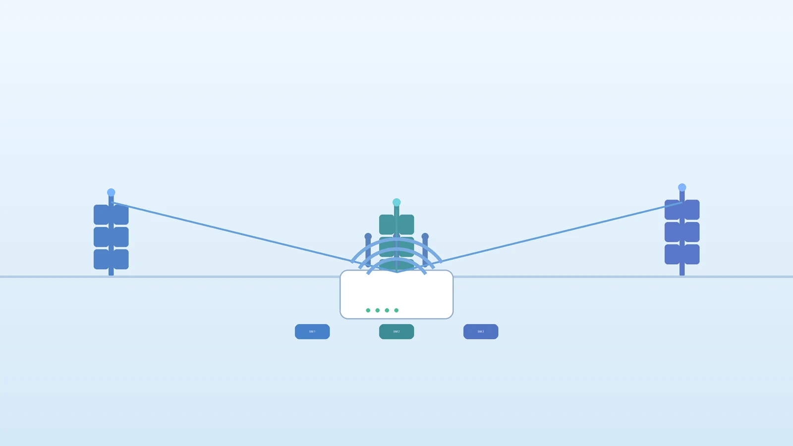
    Maritime CPE must function as an intelligent multi-WAN gateway that seamlessly integrates multiple connectivity sources:

    • Primary WAN (5G NR): Terrestrial 5G connectivity for near-shore and port operations, delivering multi-gigabit throughput with sub-20ms latency.
    • Secondary WAN (LEO/MEO/GEO Satellite): Automatic failover to satellite connectivity when beyond 5G coverage range. Modern LEO constellations (Starlink Maritime, OneWeb) now deliver 100-350 Mbps with 25-50ms latency — sufficient for most vessel operational systems during deep-sea passages.
    • Tertiary WAN (Wi-Fi as WAN): Automatic connection to marina and port Wi-Fi networks when available at berth, reducing satellite data consumption during extended port stays.

    The failover logic must be configurable with hysteresis — avoiding flapping between 5G and satellite as the vessel transits the coverage boundary. Typical parameters include minimum signal strength thresholds (e.g., RSRP > -115 dBm for >30 seconds before switching to 5G) and bandwidth-based policies (e.g., route high-volume traffic to 5G when available, keep low-bandwidth telemetry on satellite for continuity).

    Power Architecture for Marine Electrical Systems

    Vessel electrical systems present unique power challenges that CPE procurement must address:

    • Wide-input DC power: Support for 9-36V DC or 18-75V DC input ranges to accommodate 12V, 24V, and 48V marine electrical systems without external converters. Galvanic isolation (>1500V) between the DC input and the CPE chassis to prevent ground-loop corrosion.
    • Battery backup integration: Support for external 12V/24V battery banks with intelligent charging management. The CPE should gracefully power down non-essential services (high-throughput data, Wi-Fi) while maintaining critical telemetry and voice connectivity on battery.
    • Power consumption optimization: Configurable power profiles — full-performance mode for active operational periods, low-power mode for anchor/mooring periods where only periodic telemetry transmission is required. Target <15W consumption in low-power mode for extended battery operation.

    Offshore Energy: A Growing CPE Market

    Beyond vessels, offshore energy installations — wind farms, oil and gas platforms, and floating production storage and offloading (FPSO) units — represent a rapidly growing market for specialized 5G CPE. These fixed installations benefit from dedicated 5G private network deployments or directional links to shore-based macro cells, with CPE requirements that emphasize:

    • Explosion-proof certifications: ATEX Zone 2 / IECEx Zone 2 compliance for CPE installed in potentially hazardous areas on oil and gas platforms.
    • Fiber backhaul interfaces: SFP/SFP+ ports for direct fiber connection to platform LAN infrastructure when the CPE serves as the shore-to-platform WAN gateway.
    • Industrial protocol support: Modbus TCP, Profinet, and OPC-UA for integration with platform SCADA and industrial control systems.

    Certifications and Classification Society Approvals

    Maritime CPE must navigate a complex regulatory and classification landscape. Technical buyers should verify that target CPE platforms hold or are on track for:

    • Type approval from major classification societies: DNV, Lloyd’s Register, Bureau Veritas, ABS, and ClassNK type approval for maritime communication equipment.
    • Wheelmark (MED) certification: EU Marine Equipment Directive 2014/90/EU compliance for CPE destined for EU-flagged vessels.
    • FCC and CE-RED: Radio equipment compliance for 5G NR bands in target deployment regions, with specific attention to maritime mobile service allocations.
    • Inmarsat/FleetBroadband compatibility: For CPE that must coexist with existing satellite communication terminals without mutual interference.

    Procurement Checklist Summary

    When evaluating 5G CPE for maritime and offshore deployments, procurement teams should verify:

    1. Salt spray corrosion resistance: IEC 60068-2-52 severity 4+, EN 50155 enclosure classification
    2. High-gain external antenna support: 4×4 MIMO with 10+ dBi gain, N-type or QMA RF connectors
    3. Multi-WAN with intelligent failover: 5G → LEO/MEO Satellite → Wi-Fi, with configurable hysteresis
    4. Wide-input DC power: 9-36V or 18-75V DC with galvanic isolation
    5. Class society type approvals: DNV, LR, BV, ABS, or ClassNK certification
    6. Vibration and shock: IACS UR E10 or DNV GL Class B compliance
    7. Extended temperature range: -40°C to +70°C operating
    8. Industrial protocol support: Modbus TCP, OPC-UA for platform SCADA integration
    9. Low-loss cabling provisions: Support for LMR-600 or active RF-over-fiber at 20m+ cable runs

    Maritime 5G is not a niche anymore — it is a fast-growing segment where specialized CPE specifications directly determine operational capability and crew safety. For operators and integrators serving the maritime market, the CPE procurement criteria outlined here represent the minimum viable specification for production deployments in 2026.

  • A Technical Buyer’s Guide to VoNR and Voice Services Architecture in 5G CPE: IMS Integration, EPS Fallback, and Carrier-Grade Voice QoS

    A Technical Buyer’s Guide to VoNR and Voice Services Architecture in 5G CPE: IMS Integration, EPS Fallback, and Carrier-Grade Voice QoS

    While 5G CPE procurement discussions often center on throughput, spectrum support, and antenna configuration, voice service architecture remains one of the most technically nuanced — and frequently overlooked — evaluation criteria. For operators deploying FWA as a primary broadband service (especially in markets where FWA replaces xDSL and cable), the CPE must deliver carrier-grade voice quality that meets regulatory obligations and subscriber expectations. This guide examines the VoNR and IMS voice architecture considerations that technical buyers should evaluate when sourcing 5G CPE for voice-enabled FWA deployments.

    The Voice Evolution in 5G: From CSFB to VoNR

    The migration path from circuit-switched voice to fully native 5G voice has been complex. In the 4G era, VoLTE (Voice over LTE) established IMS as the core voice architecture, but early 5G NSA deployments relied on EPS Fallback (EPS-FB) — the CPE temporarily falls back to LTE for voice calls while maintaining the 5G data connection. As standalone (SA) 5G cores proliferate globally, VoNR (Voice over New Radio) is becoming the target architecture, delivering voice calls entirely within the 5G domain with improved call setup times, enhanced codec support, and superior spectral efficiency.

    For procurement teams, the critical question is not whether a CPE supports voice — it is which voice architectures are supported, and how seamlessly the transitions are managed:

    Architecture Call Setup Time Codec Support Network Dependency Maturity
    EPS Fallback 1.5-3.0s AMR-WB (HD Voice), AMR-NB LTE coverage required Widely deployed
    VoNR (5G SA) 0.8-1.5s EVS (Super-Wideband), AMR-WB 5G SA core required Growing rapidly
    VoLTE (4G anchor) 1.0-2.5s AMR-WB, AMR-NB LTE coverage Mature

    IMS Registration and SIP Stack Architecture

    At the heart of any voice-capable 5G CPE is the IMS (IP Multimedia Subsystem) client. This embedded software stack handles SIP registration with the operator’s IMS core, manages session establishment and teardown, and enforces QoS policies for voice bearer traffic. Procurement teams should evaluate the IMS implementation across several dimensions:

    • SIP stack maturity and interoperability: The CPE’s SIP implementation must interoperate with major IMS core vendors including Ericsson, Nokia, Huawei, and Mavenir. Request interoperability test reports for the specific IMS core versions deployed in target markets.
    • IMS APN/DNN configuration: Operators typically dedicate a separate APN (Access Point Name) or DNN (Data Network Name) for IMS traffic, with distinct QoS profiles. The CPE must support concurrent data and IMS PDN connections with proper routing.
    • P-CSCF discovery: The CPE should support multiple P-CSCF (Proxy-Call Session Control Function) discovery mechanisms including DHCP options, DNS-based discovery per 3GPP TS 23.228, and manual configuration for fixed-access deployments.
    • SIP registration resilience: Support for SIP outbound (RFC 5626) with keep-alive mechanisms, registration refresh timers, and graceful re-registration after network interruptions.

    Voice QoS: The 5QI Framework

    Voice quality in 5G is governed by the 5G QoS Identifier (5QI) framework, which defines standardized QoS characteristics for different traffic types. For voice services, the critical 5QI values are:

    • 5QI 1 (GBR, Conversational Voice): 100ms packet delay budget, 10⁻² packet error rate, guaranteed bit rate. This is the primary QoS class for VoNR bearer traffic and must be supported with true GBR enforcement at the CPE’s modem and application processor.
    • 5QI 5 (Non-GBR, IMS Signaling): 100ms packet delay budget, 10⁻⁶ packet error rate. Used for SIP signaling traffic; prioritizes signaling messages to prevent call setup failures under congestion.

    The CPE must correctly map these 5QI values to internal packet scheduling queues and enforce appropriate DSCP markings on the LAN side when voice traffic is bridged to an analog telephone adapter (ATA) or IP phone connected to the CPE’s Ethernet port. Failure to properly prioritize voice bearer traffic results in jitter, packet loss, and degraded Mean Opinion Score (MOS) — issues that drive subscriber churn in voice-dependent markets.

    Analog Voice Interfaces: FXS Ports and ATA Integration

    For FWA deployments that replace traditional fixed-line services, many operators require the CPE to provide FXS (Foreign Exchange Subscriber) ports for connecting existing analog telephones. This is particularly important in markets where subscribers are accustomed to plugging a standard telephone into the wall jack. The CPE’s integrated ATA (Analog Telephone Adapter) function bridges SIP-based IMS voice to analog POTS interfaces.

    Key FXS specifications to evaluate:

    • Codec transcoding: The CPE must transcode between IMS-native codecs (AMR-WB, EVS) and G.711/G.729 for the analog interface, with minimal processing delay (target: <50ms algorithmic delay).
    • Calling features: Support for caller ID (FSK and DTMF-based), call waiting, three-way calling, call forwarding, and DTMF relay (RFC 2833) — matching the feature set of a traditional PSTN line.
    • Fax and modem passthrough: T.38 fax relay and G.711 passthrough mode for legacy fax machines and point-of-sale terminals that remain common in small business FWA deployments.
    • Ring voltage and REN: Sufficient ring voltage (typically 40-55 Vrms) and Ringer Equivalence Number (REN) to drive at least 3 REN — enough for multiple parallel-connected analog phones.

    Emergency Calling and Regulatory Compliance

    Voice-capable CPE must support emergency calling (E911, E112) with accurate location information delivery. For fixed FWA deployments, the CPE should support manual location configuration via TR-069/TR-369, allowing operators to provision the installed address for emergency services routing. For nomadic FWA CPE, location determination via network-based positioning or GPS assistance becomes necessary.

    Regulatory requirements vary by market but typically include: support for emergency number dialing without prior registration, priority handling of emergency SIP INVITE messages with emergency service URNs per RFC 5031, and location-by-reference or location-by-value delivery in SIP headers.

    Procurement Checklist Summary

    When evaluating 5G CPE for voice-enabled FWA deployments, procurement teams should verify:

    1. VoNR support on target 5G SA bands with EPS Fallback as a transitional capability
    2. IMS SIP stack interoperability with major core vendors (request IoDT reports)
    3. 5QI 1 GBR enforcement for voice bearer with proper DSCP mapping on LAN ports
    4. EVS codec support (super-wideband, 13.2 kbps to 128 kbps) for superior voice quality
    5. FXS port specifications meeting regional analog telephony requirements
    6. Emergency calling support per local regulatory framework
    7. Voice MOS testing results under loaded network conditions (>3.8 MOS target)
    8. Field-upgradeable voice firmware to accommodate evolving IMS core requirements

    Voice may not dominate 5G CPE bandwidth consumption, but for operators positioning FWA as a complete fixed-line replacement, voice architecture quality is a make-or-break procurement criterion. The devices that deliver seamless, carrier-grade voice alongside multi-gigabit data are the ones that earn long-term operator contracts in 2026 and beyond.

  • 5G CPE Powers Smart City Digital Transformation: How Fixed Wireless Access Enables Connected Urban Infrastructure at Scale in 2026

    5G CPE Powers Smart City Digital Transformation: How Fixed Wireless Access Enables Connected Urban Infrastructure at Scale in 2026

    As municipalities worldwide accelerate digital transformation agendas, 5G Fixed Wireless Access (FWA) is emerging as the connective backbone for smart city infrastructure deployments. Unlike fiber-dependent architectures that require extensive trenching across urban landscapes, 5G CPE devices offer rapid deployment at a fraction of the cost and timeline — a critical advantage for cities balancing budget constraints with ambitious connectivity roadmaps.

    The Smart City Connectivity Challenge

    Modern smart city initiatives span multiple domains: intelligent traffic management systems processing real-time video feeds from thousands of intersections, environmental sensor networks monitoring air quality at neighborhood granularity, public safety cameras requiring always-on uplink capacity, digital kiosks delivering citizen services, and smart grid infrastructure managing distributed energy resources. Each use case imposes distinct network requirements that traditional wired backhaul struggles to satisfy uniformly.

    The core challenge is not bandwidth alone — it is ubiquity. A city’s digital infrastructure must reach every street corner, every utility pole, every underground sensor cluster. Fiber-to-the-pole is economically viable for perhaps 15-20% of candidate locations in a typical mid-sized city. The remaining 80% demands wireless alternatives that can deliver carrier-grade reliability without the civil engineering overhead.

    5G CPE as Universal Connectivity Nodes

    Outdoor-rated 5G CPE units are increasingly deployed as multi-purpose connectivity hubs at the network edge. A single CPE installation on a streetlight pole can simultaneously backhaul traffic camera feeds, serve public Wi-Fi access points, connect environmental monitoring arrays, and provide failover connectivity for adjacent traffic signal controllers. This consolidation model — one CPE, multiple served endpoints — dramatically reduces per-node deployment costs while simplifying ongoing network operations.

    Key architectural requirements for smart city-grade 5G CPE include:

    • Industrial-grade environmental hardening: IP67 or higher ingress protection, -40°C to +65°C operating temperature range, and UV-resistant enclosures for direct sun exposure over 10+ year deployment lifecycles.
    • Multi-gigabit backhaul capacity: Support for 5G NR Carrier Aggregation with at least 4CC on sub-6 GHz bands, delivering sustained 2+ Gbps downlink and 500+ Mbps uplink for video-heavy workloads.
    • Edge computing capability: Integrated application processors capable of running local AI inference for video analytics, reducing backhaul traffic by filtering and pre-processing data at the collection point.
    • Multi-interface LAN segmentation: Simultaneous operation of 2.5GbE PoE++ ports for cameras and access points, RS-485 serial interfaces for industrial sensor integration, and Wi-Fi 6/6E for local device connectivity.
    • Dual-SIM with eSIM flexibility: Carrier redundancy via dual physical SIM slots plus GSMA SGP.32-compliant eSIM for dynamic operator switching and multi-network resilience.

    Deployment Economics: Fiber vs. FWA

    The economic case for 5G CPE in smart city deployments is compelling. Municipal field studies from 2025-2026 indicate that trenching new fiber to a single intersection cabinet costs between $25,000 and $85,000 depending on urban density and subsurface conditions, with deployment timelines of 6-18 months. An outdoor 5G CPE installation on existing street furniture, by contrast, costs $800-$2,500 per node and can be activated within days of site survey completion.

    At city scale — hundreds to thousands of nodes — the aggregate savings run into tens of millions of dollars while accelerating time-to-service by 12-24 months. This is not merely a capex optimization; it is the difference between launching a smart city program within a single mayoral term versus deferring it across multiple budget cycles.

    Network Slicing for Multi-Tenant Municipal Networks

    5G network slicing is particularly relevant to municipal deployments where a single physical CPE must serve multiple logical tenants with distinct SLA requirements. A typical configuration might dedicate:

    • Slice 1 (Public Safety): Guaranteed low-latency, high-priority slice for emergency services video and voice, with pre-emption capability over all other traffic.
    • Slice 2 (Traffic Management): Medium-latency, high-throughput slice for real-time traffic camera analytics and adaptive signal control systems.
    • Slice 3 (Environmental IoT): Low-bandwidth, delay-tolerant slice for periodic sensor data aggregation with store-and-forward capability during congestion.
    • Slice 4 (Public Access): Best-effort slice for citizen Wi-Fi services with fair-usage throttling and content filtering.

    This multi-tenant architecture allows cities to monetize 5G infrastructure by offering differentiated connectivity services to municipal departments, utility companies, and private service providers operating within the urban footprint.

    Real-World Deployments and Lessons Learned

    Several mid-sized cities in Asia-Pacific and the Middle East are now in advanced stages of 5G CPE-based smart city rollouts. Early deployments have surfaced practical considerations that procurement teams should address:

    • Power sourcing: Streetlight poles typically provide only 100-240V AC with limited wattage headroom. CPE units should support wide-input PoE (802.3bt Type 4, up to 90W) to simplify power sourcing and eliminate the need for separate electrical circuits.
    • Mounting standardization: Cities benefit from CPE that supports standard pole-mount brackets (30-120mm diameter) and DIN-rail mounting for cabinet deployments, avoiding custom fabrication costs.
    • Remote management at scale: TR-369 USP (User Services Platform) is rapidly replacing TR-069 as the preferred device management protocol for municipal-scale deployments, offering bulk provisioning, lifecycle automation, and real-time telemetry for thousands of distributed nodes.
    • Vandalism resistance: Tamper-detection sensors, concealed antenna designs, and anti-theft mounting hardware have proven essential in deployments where CPE units are accessible at street level.

    5G-Advanced and the Next Phase

    Looking ahead to 3GPP Release 18 and beyond, 5G-Advanced features will further enhance smart city CPE capabilities. AI-native air interface optimizations will improve spectral efficiency in dense urban deployments where interference is a primary constraint. Enhanced positioning accuracy (sub-meter level) will enable precise location-based services without additional GPS infrastructure. And integrated sensing and communication (ISAC) capabilities may allow CPE units to double as environmental sensors, detecting movement patterns and environmental changes through RF signature analysis.

    For municipalities and system integrators planning 2026-2028 smart city programs, specifying 5G CPE with a clear upgrade path to 5G-Advanced features is now a prudent procurement strategy. The devices deployed today will likely remain in service for 7-10 years, spanning two generations of 3GPP releases. Selecting platforms with field-upgradeable modem modules and sufficient compute headroom for future AI workloads ensures that today’s investment remains relevant through the smart city evolution cycle.

    Conclusion

    5G CPE is no longer merely a consumer broadband alternative — it is the practical connectivity fabric for urban digital transformation. Cities that embrace FWA-based architectures for smart infrastructure gain deployment velocity, cost efficiency, and architectural flexibility that fiber-only strategies cannot match. For municipal IT directors, system integrators, and telecom procurement teams, the message is clear: the smart city starts with the right CPE at the edge.

  • A Technical Buyer’s Guide to 5G CPE QoS Architecture: Deep Packet Inspection, Traffic Shaping, and Application-Aware Policy Enforcement

    A Technical Buyer’s Guide to 5G CPE QoS Architecture: Deep Packet Inspection, Traffic Shaping, and Application-Aware Policy Enforcement

    Quality of Service (QoS) architecture in 5G CPE has evolved far beyond simple priority queuing. As enterprise FWA deployments scale to support latency-sensitive applications — from real-time industrial control to 4K video conferencing and cloud-native SaaS — procurement teams must evaluate CPE QoS capabilities with the same rigor they apply to carrier-grade routing infrastructure. This guide provides a comprehensive technical framework for assessing QoS architecture in 5G CPE for B2B procurement.

    The QoS Stack: From 5G NR Flow to LAN Egress

    Effective QoS in a 5G CPE spans three distinct domains that must operate in concert:

    • 5G NR QoS Flow (3GPP TS 23.501): The 5G core establishes QoS Flows with specific 5QI (5G QoS Identifier) values mapped to resource types (GBR, Non-GBR, Delay-Critical GBR). The CPE modem must correctly map these 5QI flows to internal traffic classes — a non-trivial task given that a single PDU session can carry up to 64 QoS Flows with distinct characteristics.
    • CPE Internal Packet Processing: Between the 5G modem and the LAN/WLAN interfaces, the CPE must perform classification, marking, policing, shaping, and queue management. This is where most enterprise CPE differentiation occurs.
    • LAN/WLAN Egress Scheduling: Traffic exiting to Ethernet switch ports or Wi-Fi radios must maintain QoS markings and enforce per-queue bandwidth allocation, especially critical in multi-tenant CPE scenarios (e.g., a single CPE serving both enterprise corporate traffic and guest Wi-Fi).

    Deep Packet Inspection: The Classification Engine

    Modern 5G CPE platforms increasingly integrate Deep Packet Inspection (DPI) engines directly into the device firmware — a capability previously reserved for dedicated enterprise firewalls and SD-WAN appliances. DPI enables application-layer traffic identification beyond simple port/protocol matching, critical for environments where applications use dynamic ports, encryption (TLS 1.3/QUIC), or CDN-distributed traffic patterns.

    Procurement Evaluation Criteria for DPI in CPE:

    • Signature Database Coverage: Minimum 3,000+ application signatures with weekly update capability. Verify coverage for enterprise-critical applications: Microsoft 365, Zoom, Teams, Salesforce, SAP, Citrix, AWS/Azure/GCP service endpoints.
    • Encrypted Traffic Analytics (ETA): The ability to classify TLS 1.3 and QUIC traffic without decryption, using machine learning on packet metadata (packet length sequences, inter-arrival times, TLS fingerprinting). Check if the CPE supports Cisco ETA-compatible or equivalent ML-based classification.
    • DPI Throughput: DPI processing should not become a bottleneck. For a 5G CPE with 2 Gbps+ downlink, the DPI engine must sustain classification at line rate with <5% CPU headroom impact.
    • First-Packet Classification Latency: <1 ms for initial flow identification; sub-100 µs for subsequent packets in established flows.

    Traffic Shaping and Hierarchical QoS (HQoS)

    Hierarchical QoS (HQoS) enables multi-level traffic scheduling — essential for CPE deployments serving diverse tenant groups or application tiers. A three-level HQoS model is becoming the de facto standard for enterprise CPE:

    • Level 1 — Subscriber/VLAN Level: Per-VLAN or per-subinterface bandwidth guarantees and caps. For example, a CPE serving a retail branch may allocate 60% of total bandwidth to POS and inventory systems (VLAN 100) and 40% to guest Wi-Fi and digital signage (VLAN 200).
    • Level 2 — Application Group Level: Within each subscriber tier, application groups receive relative priority and minimum bandwidth guarantees. Real-time communications (voice, video conferencing) receive strict-priority queuing; business-critical SaaS receives guaranteed bandwidth; bulk data and entertainment receive best-effort with fair-queuing.
    • Level 3 — Flow Level: Individual flows within application groups are scheduled using Weighted Fair Queuing (WFQ) or Deficit Round Robin (DRR) to prevent single-flow domination.

    Key HQoS Specifications to Verify:

    • Queue Depth: Minimum 8 hardware queues per port with 3-level hierarchical scheduling support. Software queues (typically 256–1024 per port) for flow-level granularity.
    • Shaper Granularity: Rate limiting at 1 kbps granularity with burst size configurability. Verify that the CPE can simultaneously shape 64+ subscriber queues at line rate.
    • Congestion Management: Support for WRED (Weighted Random Early Detection) with ECN (Explicit Congestion Notification) marking — critical for TCP throughput optimization over variable-capacity 5G links.

    Application-Aware Policy Enforcement

    Beyond classification and shaping, enterprise CPE must enforce application-aware policies that adapt to real-time network conditions. Three policy enforcement capabilities deserve particular attention in procurement evaluations:

    Dynamic Path Selection: The CPE should steer latency-sensitive applications (VoLTE/VoNR offload, real-time video) to the 5G link with the lowest measured latency, while routing bulk transfers over higher-bandwidth but higher-latency paths. Path selection decisions must be reassessed at sub-second intervals based on active probing (TWAMP, ICMP, or proprietary SLA probes).

    Application-Layer Gateway (ALG) and Protocol Awareness: SIP ALG for VoIP NAT traversal, FTP ALG for active/passive mode negotiation, and RTSP awareness for IP camera streams remain essential in enterprise environments. However, verify that the CPE’s ALG implementations are modern and do not interfere with encrypted signaling (SIP over TLS).

    Time-Based Policy Scheduling: Enterprise CPE should support calendar-based policy changes — e.g., deprioritizing entertainment traffic during business hours (08:00–18:00) while allowing full bandwidth for software updates and cloud backups during off-hours. Verify that the CPE’s policy engine supports at least 32 time-based rules with calendar integration.

    QoS Interoperability with Operator 5G Core

    A frequently overlooked aspect of CPE QoS evaluation is interoperability with the mobile network operator’s 5G core policy framework. The CPE must correctly interpret and act upon:

    • URSP (UE Route Selection Policy) Rules: Sent by the 5G core’s PCF, URSP rules instruct the CPE which PDU session (and associated QoS Flow) to use for specific application traffic descriptors. Verify that the CPE’s URSP client implementation correctly parses Traffic Descriptors (IP 5-tuple, FQDN, OSId/OSAppId) and Route Selection Descriptors (SSC mode, DNN, S-NSSAI).
    • Reflective QoS: Support for Reflective QoS (RQoS) per 3GPP TS 24.193, where the CPE derives uplink QoS rules from received downlink packet markings. This eliminates the need for explicit QoS rule signaling for symmetric traffic patterns.
    • QoS Flow to DSCP Mapping: The CPE must provide configurable mapping between 5QI values and IP DSCP/802.1p CoS markings on the LAN side, enabling end-to-end QoS continuity from the 5G core through to the enterprise LAN switch fabric.

    Testing and Validation Framework for CPE QoS

    B2B procurement teams should establish a structured QoS validation framework before finalizing vendor selection. Recommended test scenarios include:

    • Multi-Application Concurrency Test: Simultaneously run VoIP calls (G.711, 20ms packetization), 1080p video conferencing, large file transfers (HTTP/HTTPS), and cloud backup traffic. Measure per-application latency, jitter, and throughput against SLA thresholds under 80% and 95% link load.
    • QoS Policy Stress Test: Configure 64+ classification rules with nested HQoS policies and verify correct classification, shaping, and queue behavior using IxChariot, iPerf3 with DSCP marking, or commercial network test solutions.
    • Failover QoS Consistency: Verify that QoS policies persist and are correctly re-applied after CPE reboot, firmware upgrade, and WAN link failover events. Policy synchronization latency should be under 30 seconds post-recovery.
    • 5G NR Mobility QoS Continuity: For mobile or nomadic CPE use cases, verify that QoS markings and throughput guarantees are maintained across cell handovers and RAT changes (5G NR to LTE fallback).

    Procurement Recommendations

    For enterprise procurement teams evaluating 5G CPE with advanced QoS requirements, we recommend the following minimum specifications be included in RFPs effective H2 2026:

    • Integrated DPI engine with 3,000+ signatures and weekly update cadence
    • 3-level HQoS with minimum 8 hardware queues per port
    • Application-aware dynamic path selection with sub-second re-evaluation
    • Full URSP client implementation per 3GPP Release 17
    • Reflective QoS and configurable 5QI-to-DSCP mapping
    • Line-rate DPI and QoS processing at 2 Gbps aggregate throughput
    • WRED with ECN marking for TCP congestion management
    • API-driven (RESTCONF/NETCONF) QoS policy provisioning for integration with enterprise orchestrators

    As 5G FWA transitions from best-effort broadband replacement to mission-critical enterprise connectivity, QoS architecture becomes a primary differentiator — not an afterthought. CPE platforms that deliver carrier-grade traffic management with enterprise-friendly policy frameworks will define the procurement landscape through 2027 and beyond.

  • A Technical Buyer’s Guide to 5G CPE Multi-WAN and SD-WAN Integration: Link Aggregation, Failover Strategies, and Enterprise-Grade WAN Optimization

    A Technical Buyer’s Guide to 5G CPE Multi-WAN and SD-WAN Integration: Link Aggregation, Failover Strategies, and Enterprise-Grade WAN Optimization

    Enterprise network architectures are increasingly defined by multi-path WAN connectivity, and the 5G CPE sits at the center of this transformation. As organizations deploy fiber, 5G FWA, LTE, and satellite links simultaneously, the CPE’s ability to aggregate, steer, and optimize traffic across heterogeneous WAN paths has become a primary procurement criterion. This guide provides a detailed technical framework for evaluating multi-WAN and SD-WAN integration capabilities in 5G CPE for B2B deployment.

    The Multi-WAN Imperative in 5G CPE

    Three enterprise networking trends are making multi-WAN CPE a non-negotiable requirement for B2B procurement in 2026:

    • Connectivity Diversity Mandates: Regulatory frameworks in financial services (Basel Committee operational resilience principles), healthcare (HIPAA contingency planning), and critical infrastructure (NIS2 Directive in Europe) increasingly require physically diverse WAN paths with automated failover. A single-carrier 5G CPE with no multi-WAN capability cannot satisfy these compliance requirements.
    • Bandwidth Aggregation Economics: Bonding a 500 Mbps fiber link with a 300 Mbps 5G FWA link provides 800 Mbps aggregate capacity at a fraction of the cost of a dedicated 1 Gbps MPLS circuit — but only if the CPE can perform per-packet or per-flow load balancing without breaking application sessions.
    • Cloud-First WAN Architecture: As enterprises shift from hub-and-spoke MPLS to direct internet access (DIA) with cloud-hosted security (SSE/SASE), the branch CPE becomes the policy enforcement point for multi-path traffic steering — a role that demands SD-WAN-grade intelligence at the CPE level.

    Link Aggregation Architectures: Bonding vs. Load Balancing

    Multi-WAN CPE platforms offer two fundamentally different approaches to combining WAN links, and procurement teams must understand the trade-offs:

    Per-Packet Link Bonding (Tunnel-Based): Traffic is encapsulated in a bonding tunnel (typically GRE, VXLAN, or proprietary protocol) and individual packets are distributed across available WAN links using round-robin or weighted distribution algorithms. This approach provides true bandwidth aggregation — a single TCP flow can utilize the combined capacity of all links — but requires a bonding endpoint (cloud gateway, headquarters concentrator, or SD-WAN hub). Vendors including Peplink (SpeedFusion), Viprinet, and Mushroom Networks specialize in this architecture.

    Per-Flow Load Balancing (Session-Based): Each application flow (identified by 5-tuple: source IP, destination IP, source port, destination port, protocol) is assigned to a single WAN link based on configurable policies. Multiple flows from the same client can use different links simultaneously, providing aggregate throughput at the site level without per-packet bonding overhead. This approach works without a remote bonding endpoint and is supported by most enterprise CPE platforms including Cradlepoint, Sierra Wireless (Semtech), and Inseego.

    Hybrid Approaches: Advanced platforms such as Peplink’s Balance series and Cisco Catalyst Cellular Gateways support both bonding (for critical applications requiring maximum throughput) and per-flow load balancing (for general internet traffic), with policy-based selection between the two modes.

    Failover Architecture: Speed, Intelligence, and Session Preservation

    Failover performance is the single most critical multi-WAN specification for enterprise procurement — and it is also the most frequently misunderstood. Key technical parameters to evaluate:

    • Failure Detection Latency: The CPE’s link health monitoring mechanism determines how quickly a WAN failure is detected. ICMP probing to multiple targets (minimum 3 diverse IP addresses) at 500ms intervals provides sub-second detection in ideal conditions. Advanced platforms supplement active probing with interface state monitoring (link-down detection in <50ms for Ethernet/SFP+ interfaces) and BFD (Bidirectional Forwarding Detection) for sub-100ms failure detection.
    • Failover Convergence Time: From failure detection to traffic flowing on the backup link, total convergence should be under 200ms for real-time applications (voice, video). Verify this under realistic conditions — loaded links, NAT state transfer, and IPsec tunnel re-establishment all add latency beyond the raw detection interval.
    • Session Persistence: Failover must preserve existing application sessions where possible. For TCP flows, this requires the CPE to maintain consistent source NAT (SNAT) IP addressing across failover — either through a shared NAT pool or by proxying connections. For IPsec VPNs, IKEv2 Mobility and Multihoming (MOBIKE, RFC 4555) enables tunnel migration without rekeying.
    • Sub-Flow Failover: In bonded multi-WAN configurations, the failure of one member link should not disrupt traffic on remaining links. Verify that the bonding protocol maintains per-packet sequence integrity during link addition/removal events.

    SD-WAN Integration Models

    The integration of 5G CPE with SD-WAN platforms follows three primary architectural models:

    Model 1 — CPE as SD-WAN Endpoint: The 5G CPE runs a full SD-WAN software stack (VMware VeloCloud, Fortinet FortiOS, Cisco vManage, Aruba EdgeConnect) directly on the device, functioning as a self-contained SD-WAN edge. This model, exemplified by Cradlepoint’s NetCloud Exchange SD-WAN and Fortinet’s FortiExtender with integrated FortiOS, provides the tightest integration but often limits SD-WAN vendor choice.

    Model 2 — CPE as Underlay with External SD-WAN: The 5G CPE operates as a transparent WAN underlay, presenting each WAN link as a separate Ethernet VLAN or routed subinterface to an external SD-WAN appliance. This model provides maximum SD-WAN vendor flexibility and is preferred by large enterprises with existing SD-WAN deployments. The CPE’s role is to provide reliable multi-WAN connectivity with L2/L3 demarcation, leaving all traffic steering and policy decisions to the SD-WAN overlay.

    Model 3 — Cloud-Orchestrated Hybrid: The CPE provides basic multi-WAN connectivity while a cloud-based orchestrator (Cradlepoint NetCloud, Cisco Catalyst Center, Juniper Mist Cloud) provides centralized policy management, traffic steering configuration, and telemetry aggregation. This model splits the difference — simpler CPE software, centralized management, but less real-time traffic steering granularity than Model 1.

    Enterprise-Grade WAN Optimization Features

    Beyond basic multi-WAN connectivity, enterprise CPE platforms increasingly integrate WAN optimization capabilities previously delivered by dedicated appliances:

    • Forward Error Correction (FEC): For bonded tunnels over lossy links (particularly satellite and mmWave 5G), packet-level FEC can recover lost packets without retransmission. Verify FEC algorithm configurability (Reed-Solomon, XOR-based) and overhead trade-offs — typical FEC overhead ranges from 5% to 20% depending on expected loss rates.
    • TCP Acceleration and Proxy: TCP performance over high-latency WAN links benefits from TCP transparent proxying with optimized congestion control (BBR v2 or equivalent). The CPE should terminate TCP connections locally and optimize the WAN-side transport independently.
    • WAN Smoothing and Jitter Buffering: For real-time UDP traffic (VoIP, video conferencing), adaptive jitter buffers and packet reordering at the CPE can mask WAN variability. Verify configurable jitter buffer depth (20–200ms) with adaptive sizing.
    • Data Deduplication and Compression: While less critical on high-bandwidth 5G links, WAN deduplication can significantly reduce data transfer volumes for repetitive enterprise traffic patterns (software updates, file synchronization, database replication). Evaluate the deduplication cache size (minimum 4 GB recommended for meaningful hit rates).

    Procurement Specifications for Multi-WAN CPE

    For RFP development in H2 2026, we recommend the following minimum specifications for enterprise-grade multi-WAN 5G CPE:

    ParameterMinimum SpecificationPreferred Specification
    WAN Interfaces1× 5G NR (3GPP R17) + 2× 2.5GbE2× 5G NR + 2× 10GbE SFP+ + 1× satellite
    Link BondingPer-flow load balancingPer-packet bonding + per-flow steering
    Failover (Detection + Convergence)< 1 second total< 200ms total with BFD
    Session PersistenceConsistent NAT across failoverMOBIKE + NAT persistence + TCP proxy
    SD-WAN IntegrationL2/L3 underlay demarcationNative SD-WAN stack + underlay mode
    FEC SupportNot requiredConfigurable Reed-Solomon FEC
    TCP AccelerationNot requiredBBR v2 TCP proxy with WAN optimization
    Management APIRESTCONF + SNMPv3RESTCONF + NETCONF + gNMI streaming telemetry

    Testing and Validation Framework

    Before finalizing multi-WAN CPE procurement, we strongly recommend lab validation of the following scenarios:

    • Hard Failover Test: Physically disconnect the primary WAN link during active VoIP calls, video conferences, and large file transfers. Measure failover time and verify session continuity for each application type.
    • Degraded Link Test: Simulate 10% and 20% packet loss on the primary link. Verify that the CPE correctly detects degradation and initiates failover or load redistribution based on configurable SLA thresholds (latency, jitter, loss).
    • Asymmetric Bandwidth Test: Combine a 1 Gbps fiber link with a 100 Mbps LTE backup link. Verify that load-balancing algorithms correctly account for asymmetric bandwidth and do not overload the lower-capacity link.
    • VPN Failover Test: Establish IPsec tunnels over all WAN links. Verify that tunnel re-establishment on failover does not introduce >5 seconds of application disruption. Validate MOBIKE support if available.
    • Management Plane Resilience: Verify that the CPE remains manageable (API accessible, telemetry streaming) during WAN failover events, including scenarios where all WAN links are briefly unavailable simultaneously.

    Procurement Recommendations

    Multi-WAN and SD-WAN integration capabilities have become defining differentiators in the 5G CPE market. For B2B buyers, the key decision is not whether to require multi-WAN support, but rather which integration model and performance tier matches their enterprise architecture. Organizations with mature SD-WAN deployments should prioritize Model 2 (underlay demarcation) for maximum flexibility. Greenfield deployments or those seeking operational simplicity may benefit from Model 1 (integrated SD-WAN endpoint) or Model 3 (cloud-orchestrated hybrid). Regardless of architecture, sub-second failover with session persistence and per-flow traffic steering should be considered table-stakes requirements for any enterprise-grade 5G CPE in 2026.

  • Global 5G FWA and LEO Satellite Convergence Gains Traction as Operators Deploy Hybrid CPE for Universal Broadband Coverage in 2026

    Global 5G FWA and LEO Satellite Convergence Gains Traction as Operators Deploy Hybrid CPE for Universal Broadband Coverage in 2026

    The convergence of 5G Fixed Wireless Access (FWA) and Low Earth Orbit (LEO) satellite broadband is emerging as one of the most consequential infrastructure trends of 2026. As operators push toward universal service obligations and enterprises demand resilient multi-path connectivity, hybrid 5G-satellite CPE solutions are transitioning from proof-of-concept trials to commercial procurement frameworks — reshaping how B2B buyers evaluate next-generation CPE platforms.

    The Business Case for 5G-Satellite Convergence

    Three structural forces are converging to drive 5G-LEO integration into mainstream CPE procurement. First, universal coverage mandates in markets including Brazil, India, Indonesia, and sub-Saharan Africa are pushing operators to fill coverage gaps that terrestrial 5G alone cannot economically serve. Second, enterprise resilience requirements are escalating — financial services, energy, logistics, and remote industrial operations now routinely specify dual-path WAN architectures with physically diverse last-mile media. Third, LEO capacity is maturing rapidly: Starlink’s direct-to-cell service, Amazon Kuiper’s enterprise tier, and AST SpaceMobile’s satellite-to-unmodified-phone architecture are creating a competitive ecosystem that drives down terminal costs and expands integration options.

    For CPE procurement teams, the implication is clear: the 2026–2028 refresh cycle must account for devices that can natively bond terrestrial 5G NR with LEO satellite backhaul, not merely support them as bolt-on afterthoughts.

    Architecture Models: Integrated vs. Aggregated Hybrid CPE

    Two dominant architectural approaches are crystallizing in the market, each with distinct procurement implications:

    Integrated Hybrid CPE embeds both a 5G NR modem (3GPP Release 17/18 compliant) and a satellite modem (typically Ku/Ka-band phased-array) within a single enclosure, sharing a common processor, routing plane, and management interface. Huawei’s upcoming NetEngine 8000 FWA series and emerging ODM designs from Quectel and Fibocom are driving this category. Advantages include single-SKU procurement, unified QoS policy enforcement, and simplified installation. The trade-off is vendor lock-in and limited flexibility in satellite operator selection.

    Aggregated Hybrid CPE pairs a standalone 5G FWA CPE with an external satellite terminal via multi-gigabit Ethernet or SFP+ interconnect, with bonding intelligence residing in a separate SD-WAN edge device or cloud orchestrator. This model, championed by Cradlepoint, Peplink, and several Tier-1 SD-WAN vendors, offers operator-agnostic satellite selection and per-link SLA management. Procurement complexity increases — buyers must source, certify, and manage multiple device types — but the operational flexibility appeals to large enterprises with existing multi-vendor WAN estates.

    Key Technical Specifications for Procurement Evaluation

    B2B buyers evaluating hybrid 5G-satellite CPE should prioritize the following technical parameters in RFPs and vendor assessments:

    • 3GPP Release Compliance: Minimum Release 17 with NTN (Non-Terrestrial Network) support in the modem baseband. Release 18 NR-NTN enhancements for IoT-NTN and NR-NTN mobility should be on the vendor roadmap.
    • Multi-Link Bonding Protocol: Support for MP-TCP, ATSSS (Access Traffic Steering, Switching, and Splitting per 3GPP TS 24.193), or proprietary bonding with sub-50ms failover. Verify real-world failover latency under loaded conditions.
    • Satellite Band Support: Ku-band (10.7–12.75 GHz downlink) and Ka-band (17.7–20.2 GHz) with at least 256-element phased-array for electronic beam steering. L-band (1–2 GHz) and S-band (2–4 GHz) for direct-to-cell use cases where applicable.
    • Throughput Aggregation: Combined 5G + satellite throughput should reach minimum 2 Gbps downlink / 500 Mbps uplink in sub-6 GHz bands, scaling to 5 Gbps in mmWave+satellite configurations.
    • Power over Ethernet (PoE++): Outdoor units should support 802.3bt Type 4 (90W) PoE for single-cable installation, especially important for rooftop and tower-mounted deployments.
    • Edge Compute Capacity: Integrated application processor (ARM Cortex-A78 or equivalent) with minimum 4 GB RAM for running local traffic steering, DPI, and security functions without external appliance dependency.

    Operator and Ecosystem Developments in H2 2026

    Several recent developments signal accelerating market readiness. T-Mobile US and SpaceX have expanded their direct-to-cell beta to enterprise customers, with compatible CPE modules entering sampling from Qualcomm (Snapdragon X80 with NTN). In Asia-Pacific, Singtel and KDDI have jointly published an open RFP for hybrid 5G-satellite CPE targeting maritime and remote mining operations, with initial deployments planned for Q1 2027. The GSMA’s NTN Device Working Group, formed in March 2026, has released its first interoperability profile, establishing baseline certification criteria for hybrid terminals.

    On the silicon side, MediaTek’s T850 NTN-enabled modem-RF platform and Qualcomm’s X80 5G Modem-RF with integrated NB-NTN support are providing the chipset foundation for a new generation of hybrid CPE devices. Both platforms support 3GPP Release 18 NTN enhancements, including doppler pre-compensation for LEO satellite links and IoT-NTN for narrowband satellite IoT applications.

    Procurement Recommendations for B2B Buyers

    For procurement teams planning 2026–2027 CPE refresh cycles, we recommend the following phased approach:

    1. Q3 2026: Include NTN/LEO compatibility as a weighted evaluation criterion in active CPE RFPs, even if immediate satellite integration is not required. Weight at 10–15% of technical scoring.
    2. Q4 2026: Conduct lab-based interoperability testing between shortlisted 5G CPE models and at least two LEO constellation operators (Starlink Enterprise, Kuiper, or regional LEO provider).
    3. Q1 2027: Pilot hybrid 5G-satellite CPE at 5–10% of high-priority sites (remote branch offices, temporary installations, disaster recovery locations).
    4. H2 2027: Transition to NTN-native CPE as the default procurement specification for all outdoor and remote-site FWA deployments.

    The convergence of terrestrial 5G and LEO satellite connectivity represents more than a niche redundancy option — it is rapidly becoming a core architectural requirement for enterprise-grade FWA. B2B buyers who incorporate NTN compatibility into their current procurement frameworks will be better positioned to leverage the full breadth of connectivity options as the hybrid ecosystem matures through 2027.

  • A Technical Buyer’s Guide to 5G CPE IPv6 Transition Architecture: Dual-Stack, 464XLAT, and CG-NAT Strategies for Operator-Grade FWA Deployments

    A Technical Buyer’s Guide to 5G CPE IPv6 Transition Architecture: Dual-Stack, 464XLAT, and CG-NAT Strategies for Operator-Grade FWA Deployments

    As mobile network operators worldwide accelerate their transition to IPv6-only core architectures — driven by address exhaustion in IPv4 and the operational cost of maintaining Carrier-Grade NAT (CG-NAT) infrastructure at scale — the 5G CPE device layer has emerged as a critical gateway for IPv6 transition strategies. For wholesale buyers, system integrators, and enterprise procurement teams evaluating 5G FWA CPE in 2026, understanding the IP transition capabilities of candidate devices is no longer optional. It directly affects application compatibility, VPN performance, IoT sensor reachability, and total cost of ownership across the device lifecycle.

    Why IPv6 Matters for 5G CPE in 2026

    The 3GPP 5G specification has mandated IPv6 support since Release 15, and virtually every 5G SA (Standalone) core deployed today operates on an IPv6-native user plane. Major operators — including T-Mobile US, Reliance Jio, Deutsche Telekom, and China Mobile — have publicly committed to IPv6-only or IPv6-dominant architectures for their 5G SA networks, with CG-NAT positioned as a transitional bridge rather than a permanent solution.

    For CPE buyers, this shift introduces a concrete set of technical evaluation criteria that go well beyond “does it support IPv6.” The device must handle:

    • IPv6-only WAN with IPv4-only LAN clients. The most common deployment scenario in 2026: the operator provides an IPv6-only PDN connection, but the enterprise LAN still runs legacy IPv4-only devices (printers, cameras, building management systems, industrial controllers).
    • Dual-stack application coexistence. Enterprise SaaS applications, VPN concentrators, and SD-WAN endpoints may be reachable over either protocol depending on carrier peering and application provider infrastructure.
    • 464XLAT translation performance. The CPE must perform stateless IPv4-IPv6 translation at line rate without introducing latency that degrades real-time applications — particularly critical for voice, video conferencing, and industrial control traffic.

    Key Architectural Components to Evaluate

    1. WAN-Side IP Stack: Dual-Stack vs. IPv6-Only with CLAT

    The most mature approach is dual-stack WAN, where the CPE receives both an IPv6 prefix (via DHCPv6-PD or SLAAC) and an IPv4 address from the 5G core. This provides maximum compatibility but requires the operator to maintain dual-stack infrastructure — precisely the operational burden that IPv6-only cores aim to eliminate.

    The emerging standard is IPv6-only WAN with CLAT (Customer-side Translator), defined in RFC 6877 (464XLAT). In this architecture, the CPE receives only an IPv6 address/prefix from the 5G core, a CLAT function embedded in the CPE performs stateless NAT46 translation for IPv4-only LAN clients, and the operator provides a PLAT (Provider-side Translator) in the core network.

    For buyers, the critical evaluation point is whether the CPE’s CLAT implementation is hardware-accelerated (via NPU or dedicated packet processing engine) or software-based. Hardware-accelerated CLAT can sustain 2–5 Gbps of NAT46 throughput with sub-millisecond latency; software CLAT may cap at 300–800 Mbps and introduce 2–5ms of additional latency per packet.

    2. LAN-Side DHCP and DNS Architecture

    IPv6 transition puts significant pressure on the CPE’s LAN-side services. Buyers should verify:

    • DNS64/NAT64 integration. The CPE must synthesize AAAA records for IPv4-only destinations (DNS64) and route the resulting traffic through a NAT64 gateway. Poor DNS64 implementations can break DNSSEC validation.
    • DHCPv6-PD sub-delegation. Enterprise deployments often require the CPE to sub-delegate IPv6 prefixes to downstream routers or VLANs. Verify that the device can receive a /56 or /48 prefix and delegate /60 or /64 sub-prefixes.
    • Happy Eyeballs v2 (RFC 8305) support. The CPE should not interfere with endpoint Happy Eyeballs algorithms. Some CPE ALG implementations inadvertently break dual-stack connection racing.

    3. Firewall, ALG, and Application Layer Gateway Behavior

    IPv6 introduces a fundamentally different security model at the CPE. Unlike IPv4, where NAT provides implicit ingress filtering, IPv6’s end-to-end architecture requires explicit stateful firewall rules. Buyers should evaluate stateful IPv6 firewall with default-deny inbound, RFC 4890 compliant ICMPv6 handling, and ALG transparency for SIP, FTP, and other protocols that rewrite IP addresses in application-layer payloads.

    4. VPN and SD-WAN Interoperability

    Enterprise VPN clients — IPSec, WireGuard, OpenVPN, and SD-WAN edge appliances — exhibit varying levels of IPv6 compatibility. The CPE must pass IPv6-encapsulated VPN traffic transparently, support IPv6 WAN addressing for management plane TR-069/TR-369 USP sessions, and handle fragmented IPv6 packets correctly.

    The CG-NAT Sunset Horizon

    Operators worldwide are beginning to signal CG-NAT sunset timelines. T-Mobile US has indicated that its 5G SA core will move to IPv6-only with 464XLAT as the default CPE configuration by 2027. European operators following GSMA IPv6 transition guidelines are on similar trajectories. For CPE buyers, this means devices purchased today on 3–5 year deployment cycles will almost certainly need to operate in IPv6-dominant environments within their service lifetime.

    Honlly’s IPv6 Transition Architecture

    Honlly Telecom’s 5G CPE portfolio implements hardware-accelerated 464XLAT CLAT with dedicated packet processing engines capable of sustaining multi-gigabit NAT46 throughput at wire speed. The platform supports both dual-stack and IPv6-only WAN modes, with dynamic mode selection via TR-369 USP provisioning. Enterprise features including DHCPv6-PD sub-delegation, RFC 4890-compliant ICMPv6 filtering, and transparent VPN passthrough are standard.

    Evaluation Checklist for IPv6 Transition

    1. CLAT performance: Hardware-accelerated with verified throughput ≥ 1 Gbps NAT46
    2. DNS64/NAT64: Embedded DNS64 with RFC 7050-compliant NAT64 discovery
    3. Firewall: Stateful IPv6 firewall with default-deny inbound, RFC 4890 ICMPv6
    4. Prefix delegation: DHCPv6-PD with sub-delegation to LAN interfaces
    5. VPN transparency: WireGuard, IPSec, and SD-WAN passthrough validated

    For detailed technical specifications on Honlly’s 5G CPE IPv6 capabilities, visit honllytelecom.com/products or contact the Honlly B2B engineering team.

  • A Technical Buyer’s Guide to 5G CPE Zero-Touch Provisioning: TR-369 USP, Device Lifecycle Automation, and Operator-Grade Remote Management Frameworks

    A Technical Buyer’s Guide to 5G CPE Zero-Touch Provisioning: TR-369 USP, Device Lifecycle Automation, and Operator-Grade Remote Management Frameworks

    As 5G FWA deployments scale from thousands to millions of CPE units per operator, the economics of device provisioning have shifted from a manageable operational expense to a strategic bottleneck. The cost of dispatching a field technician to install and configure a single CPE — estimated at $75–$180 per truck roll across major markets — becomes untenable at scale. Zero-Touch Provisioning (ZTP), enabled by the Broadband Forum’s TR-369 User Services Platform (USP) standard, has emerged as the definitive answer. For B2B buyers and system integrators sourcing 5G CPE in 2026, understanding ZTP architecture is a prerequisite for operator certification and large-scale deployment eligibility.

    From TR-069 to TR-369: The Management Protocol Transition

    The broadband industry’s CPE management backbone has been TR-069 (CWMP) for nearly two decades. While TR-069 served DSL, cable, and early LTE FWA deployments adequately, its limitations in a 5G context are well documented:

    • HTTP-based polling model introduces latency and overhead unsuitable for real-time 5G service orchestration
    • Single CPE-to-ACS relationship cannot support multi-tenant, multi-service architectures required by network slicing and private 5G
    • Limited data model extensibility makes it difficult to expose 5G-specific parameters (CSI-RS measurements, beam management state, slice configuration) without proprietary vendor extensions
    • No native IoT device proxy capability — TR-069 assumes every managed endpoint is a CPE, whereas TR-369 USP can proxy manage connected IoT sensors, mesh nodes, and enterprise LAN equipment

    TR-369 USP (User Services Platform), standardized by the Broadband Forum as USP 1.3 in 2024 and USP 1.4 targeted for H2 2026, addresses these limitations through a fundamentally modern architecture:

    • WebSocket and CoAP transport with MQTT broker integration for real-time, bidirectional communication
    • Multi-controller architecture allowing a single CPE to be simultaneously managed by an operator ACS, enterprise IT controller, and security analytics platform
    • USP Services model that cleanly separates device management, firmware lifecycle, network diagnostics, and IoT proxy functions
    • End-to-end security with TLS 1.3 mutual authentication and USP Endpoint Identity certificates

    Zero-Touch Provisioning Architecture

    Phase 1: Bootstrap and Discovery

    When a CPE powers on for the first time, it must autonomously discover its management controller without any prior configuration. The bootstrap sequence typically follows DHCP/DHCPv6 option-based discovery (the most common method in carrier deployments), DNS-SD/mDNS fallback for enterprise deployments, or a pre-configured bootstrap URL for managed service providers.

    The key evaluation criterion for buyers: how many bootstrap discovery methods does the CPE support, and can they be prioritized in a configurable fallback chain?

    Phase 2: Secure Onboarding and Identity

    Once the controller URL is discovered, the CPE establishes a mutually authenticated TLS 1.3 session. The device identity model is critical: factory-installed X.509 device certificates (IEEE 802.1AR DevID) burned into secure storage (TEE or TPM) during manufacturing provide cryptographic device identity — the gold standard mandatory for operator-grade ZTP. Buyers should verify that the CPE supports hardware-backed key storage (TrustZone, Secure Enclave, or discrete TPM) for device certificates and can perform CSR generation for operator PKI integration.

    Phase 3: Parameter Provisioning

    After secure onboarding, the controller pushes the full service configuration via USP Set messages: WAN configuration (APN/DNN, PDU session parameters, URSP rules), LAN configuration (DHCP pools, VLANs, SSIDs, firewall rules), voice configuration (SIP proxy, codec preferences), and QoS mapping (DSCP-to-QFI mapping tables). The entire provisioning sequence — from power-on to fully configured service — should complete in under 90 seconds for typical FWA deployments and under 3 minutes for complex enterprise configurations.

    Phase 4: Ongoing Lifecycle Management

    ZTP is not a one-time event; it extends across the CPE lifecycle with firmware lifecycle management via segmented, scheduled, and conditional USP upgrades; telemetry and performance monitoring with real-time KPI streaming; remote diagnostics with ping, traceroute, packet capture, and modem log collection; and secure decommissioning with factory reset, certificate revocation, and secure wipe.

    Evaluation Criteria for CPE ZTP Capability

    1. USP Protocol Compliance

    Verify USP 1.3 (or later) with WebSocket transport and TLS 1.3 mutual authentication, MQTT transport support, CoAP transport with DTLS for constrained IoT scenarios, at least 15 concurrent controller connections, and USP MTP with fragmentation and reassembly for large payloads.

    2. Bootstrap Mechanism Flexibility

    The CPE should support all three bootstrap discovery methods (DHCP options, DNS-SD/mDNS, pre-configured URL) with configurable priority and timeout parameters.

    3. Hardware-Backed Security

    Mandatory: X.509 device certificate in factory-secured storage, secure boot chain, TLS 1.3 with PFS cipher suites, and certificate renewal without factory reset.

    4. Data Model Coverage

    The CPE must expose a comprehensive TR-181 Device:2 data model covering Device.Cellular (5G modem parameters, cell measurements), Device.WiFi (SSID, band steering, client statistics), Device.Routing (static routes, policy routing, VRF instances), Device.Bridging (VLANs, IGMP/MLD snooping), and Device.QoS (classification, queuing, DSCP marking).

    5. Multi-Tenant and Slicing Support

    For private 5G and network slicing deployments, the CPE must support multiple PDU sessions with independent USP controller associations, URSP rule provisioning via USP, and per-slice telemetry and QoS monitoring.

    Honlly’s ZTP Implementation

    Honlly Telecom’s 5G CPE portfolio implements TR-369 USP 1.3 across all current-generation devices, with a field-upgradable path to USP 1.4. Key differentiators include factory-installed X.509 device certificates with hardware-backed key storage in ARM TrustZone, a multi-controller architecture supporting simultaneous operator, enterprise, and cloud management connections, comprehensive TR-181 Device:2 data model coverage, conditional firmware upgrade engine, and zero-touch bootstrap time under 75 seconds for typical FWA deployments.

    The ZTP Imperative for 2026–2027

    Operators issuing RFPs for 5G CPE in H2 2026 are increasingly making TR-369 USP compliance a mandatory gate criterion — not a “nice-to-have.” The days of TR-069 as an acceptable minimum are ending. For CPE buyers serving operator channels, ZTP readiness determines whether a device can be listed on an operator’s approved CPE roster at all.

    When evaluating 5G CPE for ZTP capability, treat USP compliance as a pass/fail gate. Devices that pass should then be scored on bootstrap flexibility, security architecture, and data model depth. The CPE that provisions fastest, most securely, and with the richest data model will deliver the lowest operational cost over a 3–5 year deployment lifecycle.


    For detailed technical documentation on Honlly’s TR-369 USP implementation and ZTP capabilities, visit honllytelecom.com/products or contact the Honlly B2B solutions engineering team.