
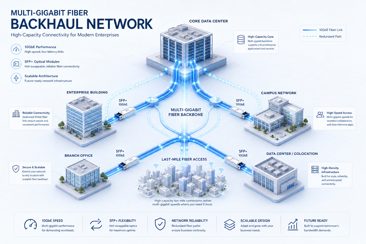
As 5G networks evolve toward 5G-Advanced and operators activate carrier aggregation configurations delivering 4–7 Gbps of aggregate throughput, the traditional Gigabit Ethernet CPE backhaul becomes the binding constraint on end-to-end performance. Enterprise and high-end residential FWA deployments increasingly require multi-gigabit backhaul architectures that can match 5G air interface capacity without introducing bottlenecks at the LAN edge. This guide examines the hardware architecture, interface selection, and deployment considerations for next-generation multi-gigabit 5G CPE backhaul design.
The Multi-Gigabit Imperative: Why 1GbE Is No Longer Sufficient
The mathematics of 5G throughput evolution are straightforward and compelling. A 5G CPE operating in a 3CC CA configuration — aggregating, for example, 100 MHz of n78 (3.5 GHz) at 4×4 MIMO, 40 MHz of n41 (2.6 GHz) at 4×4 MIMO, and 20 MHz of n28 (700 MHz) at 2×2 MIMO — can realistically achieve physical-layer throughput of 5–6 Gbps in downlink under favorable RF conditions with 256QAM modulation. When networks upgrade to 5G-Advanced with 1024QAM and additional carrier aggregation combinations, the achievable throughput pushes toward 8–10 Gbps.
A CPE with only a 1GbE LAN port becomes the bottleneck: the 5G modem can receive data at 5 Gbps, but the CPE can only deliver 940 Mbps (after Ethernet overhead) to the LAN. The result is 80%+ of the available 5G capacity going unused — a waste of expensive spectrum assets and CPE silicon investment. Multi-gigabit backhaul is not a nice-to-have; it is an architectural requirement for extracting full value from mid-band 5G spectrum investments.
Interface Options: 2.5GbE, 5GbE, 10GbE, and SFP+
Modern 5G CPE designs have several options for breaking the Gigabit Ethernet barrier, each with distinct trade-offs in cost, power consumption, cabling compatibility, and deployment complexity:
2.5GbE (NBASE-T)
IEEE 802.3bz, ratified in 2016, defines 2.5GBASE-T and 5GBASE-T operation over Cat5e and Cat6 cabling — the same infrastructure already installed in most enterprise and residential environments. For FWA deployments, 2.5GbE offers the most pragmatic upgrade path: it provides 2.5 Gbps of backhaul capacity over existing Cat5e cabling at cable lengths up to 100 meters, with per-port power consumption typically under 1.5W. For operators deploying CPE in existing buildings where recabling is impractical or cost-prohibitive, 2.5GbE represents the minimal-friction path to multi-gigabit performance.
The limitation, of course, is throughput headroom. A 2.5GbE backhaul can handle today’s typical 3CC CA throughput (2–3 Gbps of IP-layer throughput after protocol overhead) but provides limited headroom for future upgrades to 4CC CA or 1024QAM modulation. It is a pragmatic near-term solution rather than a future-proof investment.
5GbE (NBASE-T)
5GBASE-T occupies the middle ground: sufficient throughput to handle current and near-future 5G-Advanced configurations while maintaining Cat6 cabling compatibility. At approximately 3–4W per port, the power budget increase over 2.5GbE is modest. For CPE targeting premium enterprise and high-end residential segments, 5GbE offers an attractive balance of performance, cabling compatibility, and cost.
However, 5GbE PHY adoption in downstream equipment (switches, routers, access points) lags behind 2.5GbE and 10GbE. Buyers should verify that the broader network infrastructure can actually leverage 5GbE link rates before specifying it as a CPE requirement.
10GbE (10GBASE-T)
10GBASE-T delivers the maximum electrical Ethernet throughput available, but with significant trade-offs: Cat6a (or Cat7) cabling is required for the full 100-meter reach, per-port power consumption typically ranges from 2.5–5W (substantially higher at the PHY level than 2.5GbE), and the silicon cost for 10GBASE-T PHYs remains a meaningful BOM adder. For enterprise CPE deployed in greenfield environments with structured Cat6a cabling, 10GBASE-T provides ample throughput headroom for the entire lifecycle of a 5G-Advanced deployment.
The practical reality for many FWA deployments is that 10GBASE-T is over-engineered for current throughput requirements, and the combination of higher power consumption and cabling constraints makes it a niche choice for specific high-end enterprise scenarios rather than a mass-market solution.
SFP+ Fiber Uplink
For enterprise deployments where the CPE serves as a primary WAN edge device connecting to a corporate LAN switch or SD-WAN appliance, an SFP+ cage offers compelling advantages over copper Ethernet:
- Media Flexibility: The operator or enterprise can select the appropriate SFP+ module for the deployment scenario — single-mode fiber (10 km+ reach), multi-mode fiber (300m at OM3), direct-attach copper (DAC) for in-rack connections, or even 10GBASE-T SFP+ modules for copper compatibility. This flexibility eliminates the need for different CPE hardware SKUs for different backhaul media.
- Electrical Isolation: Fiber connections provide galvanic isolation between the outdoor CPE and indoor equipment, protecting against ground potential differences and lightning-induced surges — a significant reliability advantage for outdoor CPE deployments.
- Future Upgrade Path: A CPE with an SFP+ cage (supporting 10 Gbps) can later accommodate 25GbE SFP28 modules if required by future 6G or millimeter-wave deployments, extending the hardware lifecycle without replacing the CPE.
The primary trade-off is that SFP+ requires fiber cabling infrastructure or at minimum an SFP+ module purchase, adding deployment complexity and cost for scenarios where copper is already available. For greenfield enterprise deployments with structured fiber cabling, however, SFP+ is frequently the optimal choice.
Multi-Gigabit Switch Fabric and Packet Processing
Beyond the physical interface, the CPE’s internal packet processing architecture must be capable of sustaining multi-gigabit throughput without becoming the bottleneck. Key hardware design considerations include:
Hardware NAT Acceleration: At multi-gigabit rates, software-based NAT processing on a general-purpose CPU becomes a severe bottleneck. CPE designs must incorporate hardware NAT/NAPT engines — typically integrated into the SoC’s packet processor or implemented in a dedicated flow-offload ASIC — capable of sustaining line-rate NAT at 5–10 Gbps with connection tracking for hundreds of thousands of simultaneous flows.
Switch Fabric Bandwidth: The internal switch fabric connecting the 5G modem (via PCIe 3.0/4.0 or USXGMII), the multi-gigabit Ethernet PHYs, the Wi-Fi chipset, and the application processor must be dimensioned for worst-case aggregate throughput. A CPE advertising 5GbE LAN and Wi-Fi 7 (theoretical 30+ Gbps aggregate) must have a switch fabric capable of handling simultaneous wired and wireless traffic at these rates without blocking or excessive buffering latency.
Buffer Management and QoS: At multi-gigabit rates, buffer sizing and QoS queue management become critical for maintaining low latency under load. Smart queue management (SQM) algorithms — fq_codel, CAKE — must operate efficiently at line rate, and buffer sizes must be tuned to prevent bufferbloat without causing unnecessary packet loss during traffic bursts.
Thermal and Power Design for Multi-Gigabit CPE
Multi-gigabit interfaces introduce non-trivial thermal challenges. A 10GBASE-T PHY can dissipate 3–5W under full load — comparable to the power consumption of an entire entry-level CPE SoC. When combined with a high-performance 5G modem (3–6W), Wi-Fi 7 chipset (3–8W), and application processor, the total thermal design power (TDP) of a multi-gigabit CPE can approach 20–25W.
Effective thermal management requires:
- Strategic component placement separating high-power devices (10GbE PHY, 5G modem, Wi-Fi PA) to avoid thermal coupling.
- Adequate heatsinking with thermal interface materials (TIMs) rated for the component temperature ranges.
- Thermal throttling policies that gracefully degrade non-critical functions (e.g., reducing Wi-Fi transmit power or switching to a lower Ethernet link rate) before impacting 5G connectivity.
- For outdoor CPE, passive cooling designs that can dissipate 20W+ in direct sunlight at 55°C ambient — a significantly more demanding thermal envelope than indoor CPE.
Deployment Architecture Patterns
Multi-gigabit 5G CPE backhaul enables several deployment architectures that are impractical with 1GbE-limited devices:
CPE-as-Primary-WAN-Edge: The CPE connects directly to the enterprise SD-WAN appliance or core switch via SFP+ fiber or 10GbE copper, serving as the primary WAN link with no intermediate router. This eliminates a point of failure and reduces latency by one network hop.
Aggregated Multi-CPE: In bandwidth-intensive enterprise scenarios, two or more 5G CPE devices with multi-gigabit backhaul can be aggregated via LACP (Link Aggregation Control Protocol) or SD-WAN load balancing, providing combined throughput of 8–10 Gbps with automatic failover.
Distributed Wi-Fi Backhaul: The CPE’s multi-gigabit LAN port connects to a multi-gigabit PoE switch powering Wi-Fi 7 access points throughout the premises. This architecture ensures that the wired backhaul from CPE to APs does not become the bottleneck even as Wi-Fi 7’s multi-link operation (MLO) delivers 4–6 Gbps of actual throughput per AP.
Evaluation Criteria for Technical Buyers
When evaluating multi-gigabit 5G CPE backhaul solutions, technical buyers should consider:
- Throughput Validation: Has the CPE demonstrated sustained multi-gigabit throughput (not just link rate) in independent testing? Request RFC 2544 or Y.1564 test results showing throughput, latency, and frame loss at 2.5G, 5G, and 10G link rates.
- Hardware NAT Performance: What is the CPE’s NAT throughput with 64-byte and 1500-byte packet sizes? Is hardware acceleration active for all packet sizes and protocol combinations (TCP, UDP, GRE, IPsec)?
- Cabling Compatibility: For NBASE-T interfaces, does the CPE support auto-negotiation down to 1GbE and 100MbE for backward compatibility with existing cabling that cannot sustain 2.5/5G link rates?
- Power Budget: What is the CPE’s total power consumption at peak multi-gigabit throughput? Is PoE++ (802.3bt) power delivery supported for outdoor units, and what is the maximum cable length at each power class?
- Thermal Validation: Has the CPE been tested for sustained multi-gigabit operation at the highest rated ambient temperature? Request thermal throttling behavior documentation.
- Firmware Maturity: Multi-gigabit PHY drivers, flow offload engines, and buffer management algorithms involve complex firmware. Assess the vendor’s track record for shipping stable multi-gigabit firmware and their vulnerability disclosure and patch management process.
Investing in multi-gigabit backhaul architecture today positions enterprise FWA deployments to fully capitalize on 5G-Advanced throughput gains over the next 3–5 years. By evaluating CPE against the detailed criteria outlined in this guide, technical buyers can ensure that their chosen platform delivers not just a high link rate but sustained, reliable, and thermally viable multi-gigabit performance in real-world deployment conditions.