When a telecom operator deploys 50,000 outdoor 5G CPE units across Southeast Asia, the first engineering question isn’t about throughput — it’s about whether those devices will survive 45°C ambient temperatures, monsoon humidity, and direct solar radiation for five years without failing. Thermal design and environmental hardening are not afterthoughts in outdoor CPE engineering; they are the foundation of field reliability and total cost of ownership.
The Thermal Challenge: Why Outdoor CPE Runs Hotter Than You Think
An outdoor 5G CPE operates in a fundamentally hostile thermal environment. Unlike indoor gateways that sit in air-conditioned rooms, outdoor units face three compounding heat sources simultaneously: solar radiation loading on the enclosure surface (up to 1,000 W/m² at peak), internal heat dissipation from the 5G modem and RF front-end (typically 8–15 W for a Cat 19 modem plus mmWave IF), and ambient air temperatures that can exceed 50°C in direct-sun installations across the Middle East, Africa, and South Asia.
The result is a junction temperature (Tj) at the modem chipset that can spike well above 105°C — past the safe operating threshold for most commercial 5G SoCs — if thermal management isn’t designed properly from the silicon up. Qualcomm’s X65/X70 modem families specify a maximum Tj of 105°C, while MediaTek’s T750 recommends staying below 100°C for sustained operation. Exceeding these limits triggers automatic CPU throttling, which reduces throughput — sometimes by 40% or more — and accelerates electromigration-related degradation in the chip interconnects over time.
Passive Cooling Architecture: The Gold Standard for Zero-Maintenance Deployments
For outdoor CPE, passive cooling is the dominant design choice — and for good reason. Active cooling (fans) introduces a single point of mechanical failure: fan bearings wear out, dust ingress clogs airflow paths, and fan failure in a sealed enclosure often goes undetected until the modem overheats and the subscriber calls support. For a carrier deploying at scale, every active cooling fan in the field is a future truck roll waiting to happen.
A well-engineered passive cooling system for outdoor 5G CPE relies on four interconnected design elements:
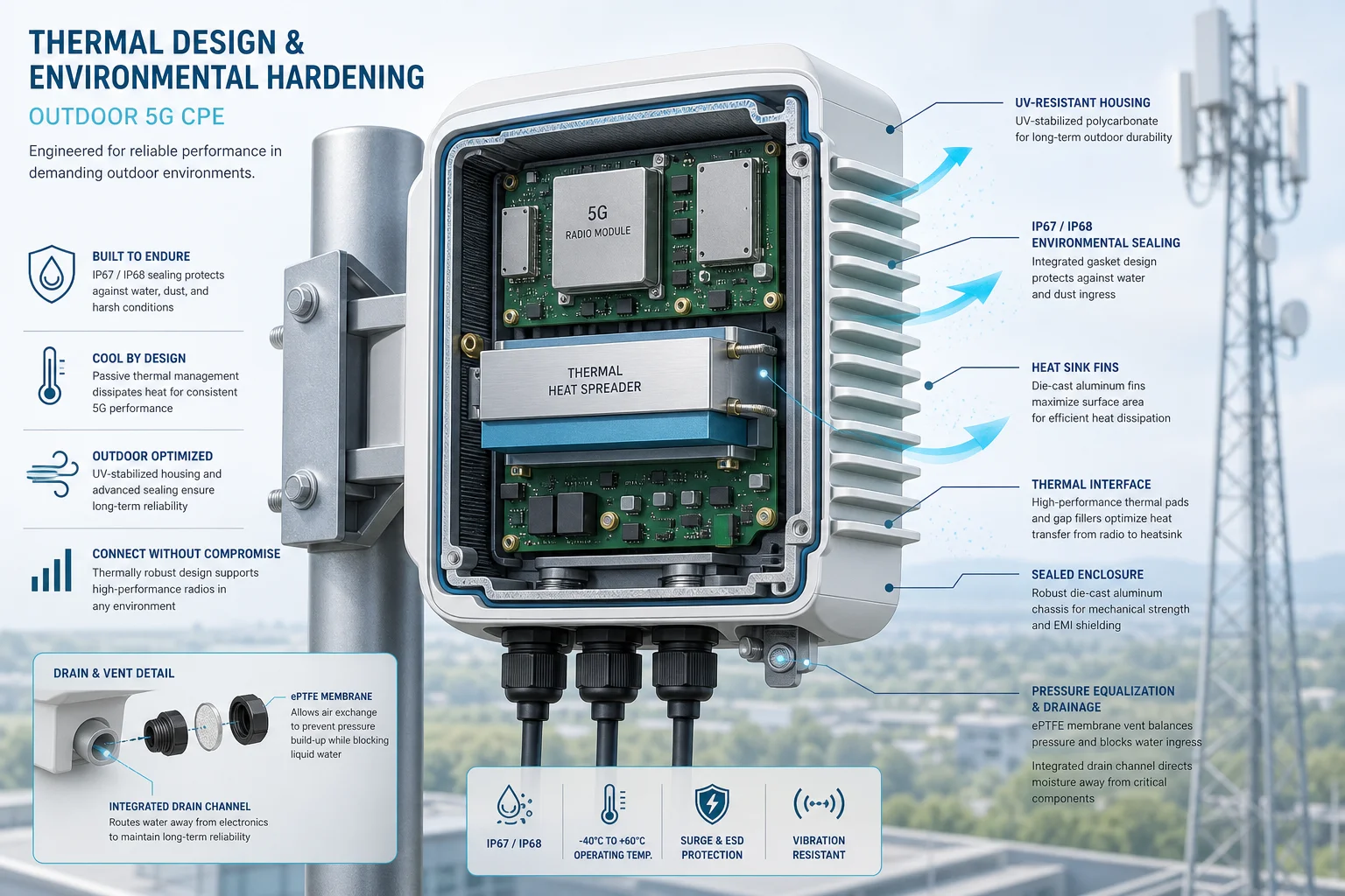
1. Die-Cast Aluminum Enclosure as Heat Spreader. The enclosure itself becomes the primary heat sink. High-thermal-conductivity die-cast aluminum alloys (ADC12 or A380, with thermal conductivity ~96 W/m·K) are used to spread heat from the internal PCB hot spots — primarily the modem SoC, PMIC, and PA — across the entire enclosure surface. A finned exterior increases the convective surface area by 3× to 5× compared to a smooth wall, dramatically improving passive heat dissipation to ambient air.
2. Thermal Interface Materials (TIM). The critical interface between the chipset heat spreader and the aluminum enclosure wall. High-performance gap fillers and thermal pads — typically silicone-based materials with 3–6 W/m·K conductivity — bridge the air gap between PCB-mounted components and the enclosure. In best-in-class designs, graphite sheets or vapor chambers are used for hotspot spreading before the heat reaches the enclosure, reducing the thermal resistance by 20–30% compared to direct pad-only coupling.
3. Internal Air Convection Optimization. Even in a sealed enclosure, internal air circulation matters. Strategic placement of internal baffles and component layout that avoids stagnant air pockets can improve heat transfer to the outer walls by 15–25%. CFD simulation during the mechanical design phase is now standard practice for serious CPE OEMs — it’s the difference between a design that works on paper and one that works in the field.
4. Solar Radiation Management. The enclosure surface finish matters enormously. A white or light-colored powder-coated aluminum enclosure can reflect 80–85% of incident solar radiation, reducing the solar heat load by over 500 W/m² compared to a dark-colored enclosure. For rooftop and pole-mounted units that cannot avoid direct sun exposure, solar radiation shields — essentially a secondary roof above the main enclosure with an air gap — can reduce internal temperature rise by an additional 8–12°C.
IP Rating Selection: Matching Protection Level to Deployment Environment
The IP (Ingress Protection) rating is the most commonly cited environmental specification for outdoor CPE — but it’s also one of the most misunderstood. An IP rating is not a single number and choosing the wrong rating for a given deployment environment can lead to premature field failures.
IP65 (Dust-tight + Water Jets). Suitable for sheltered outdoor installations — under eaves, in weatherproof cabinets, or pole-mounted with a rain hood. IP65 protects against low-pressure water jets from any direction. It is the minimum acceptable rating for any outdoor CPE deployment, but it is not sufficient for fully exposed installations in high-rainfall regions.
IP67 (Dust-tight + Temporary Immersion). The sweet spot for most outdoor 5G CPE deployments. IP67 guarantees survival during temporary immersion in up to 1 meter of water for 30 minutes — which covers the worst monsoon flooding scenarios that fixed wireless access operators face in tropical deployment zones. Most carrier RFPs for outdoor CPE now specify IP67 as the baseline requirement.
IP68 (Dust-tight + Continuous Immersion). Required for deployments in flood-prone areas or installations below ground level. IP68 testing conditions are specified by the manufacturer (not the standard), so procurement teams should verify the exact test parameters — depth and duration — rather than accepting “IP68” at face value. Typical outdoor CPE IP68 ratings specify 1.5–2 meters for 30–60 minutes.
A critical procurement note: IP rating tests are performed on brand-new units in laboratory conditions. Real-world IP performance degrades over time as gaskets age, UV exposure embrittles seals, and thermal cycling stresses the enclosure. Operators should request accelerated aging test data — specifically 1,000-hour UV exposure and 500-cycle thermal shock testing (-40°C to +85°C) — from CPE vendors before large-scale procurement.
Conformal Coating and PCB-Level Protection
Even with an IP67-rated enclosure, condensation remains a threat. Daily thermal cycling — cool nights followed by hot days — causes internal humidity to condense on PCB surfaces. This is where conformal coating becomes essential.
Conformal coating — typically acrylic, silicone, or parylene — is applied as a thin protective film (25–75 μm) over the PCB assembly. It prevents moisture-induced dendritic growth (electrochemical migration) between adjacent solder pads, which is a leading cause of latent field failures in outdoor electronics.
For outdoor 5G CPE, silicone-based conformal coatings (SR-type) are preferred over acrylic (AR-type) for three reasons: higher operating temperature tolerance (up to 200°C vs. 125°C), better flexibility during thermal cycling, and superior hydrophobicity that prevents water film formation on coated surfaces. Leading CPE OEMs apply conformal coating using selective robotic spray systems that achieve 100% coverage on both sides of the PCB while leaving connectors and test points masked.
Field Failure Analysis: What Actually Kills Outdoor CPE
Field return data from multiple carrier deployments reveals a consistent pattern of outdoor CPE failure modes, ranked by frequency:
- Water Ingress (35–40% of field failures). Not catastrophic flooding — slow, cumulative moisture ingress through degraded gaskets, cable gland seals, or UV-damaged enclosure seams. Failures typically appear 18–36 months into deployment, after multiple wet seasons. The root cause is almost always gasket compression set: silicone O-rings that permanently deform under sustained compression and fail to rebound during thermal cycling.
- Thermal Throttling-Related Degradation (20–25%). Modems that repeatedly hit Tj limits experience accelerated NBTI (Negative Bias Temperature Instability) in their silicon, leading to gradual timing margin erosion and eventual intermittent failures. These are the hardest failures to diagnose because the unit often works normally when tested in a cooler lab environment.
- Lightning-Induced Surge Damage (15–20%). Even with Ethernet surge protection, nearby lightning strikes induce voltage transients on outdoor cabling. IEC 61000-4-5 Class 4 surge immunity (4 kV line-to-ground) is the minimum standard for outdoor CPE in lightning-prone regions. Units with only Class 2 protection (1 kV) show 3× higher field failure rates in tropical deployment zones.
- UV Degradation of External Components (10–15%). Plastic radome covers, cable glands, and external antenna connectors degrade under years of UV exposure. Polycarbonate radomes without UV stabilizers can lose 50% of their impact strength within 3 years of tropical sun exposure. Specification of UV-stabilized materials (UV rating F1 per UL 746C) should be mandatory in CPE procurement RFPs.
- Connector Corrosion (5–10%). SIM card contacts, Ethernet jack pins, and DC power connectors corrode when even trace amounts of moisture combined with industrial pollutants (sulfur dioxide, hydrogen sulfide) create acidic micro-environments. Gold-flashed contacts with 30 μ” minimum gold thickness over nickel underplate provide the best corrosion resistance for outdoor applications.
Procurement Checklist: What Operators Should Demand from CPE Vendors
When evaluating outdoor 5G CPE for large-scale fixed wireless access deployments, procurement teams should require the following environmental qualification data from vendors — not just a datasheet IP rating:
- Thermal design validation report including CFD simulation results and measured Tj at 55°C ambient under sustained full-load operation (minimum 4-hour soak test)
- IP rating test certificates from an ISO 17025 accredited laboratory (not self-certified)
- Accelerated life test data: 1,000-hour damp heat (85°C/85% RH), 500-cycle thermal shock (-40°C to +85°C), 1,000-hour salt spray (ASTM B117)
- Conformal coating specification with coating type, coverage percentage, and IPC-CC-830 certification
- Surge immunity test reports per IEC 61000-4-5 at required protection class level
- UV resistance qualification per UL 746C for all external non-metallic components
- Gasket material datasheet with compression set values after thermal aging (per ASTM D395 Method B)
- Field failure rate data from existing deployments in comparable climatic zones, with mean time between failures (MTBF) calculated per Telcordia SR-332 Issue 4
Deployment Best Practices: Engineering the Installation for Reliability
Even the best-designed outdoor CPE will fail prematurely if installed incorrectly. Operator field teams should follow these deployment guidelines:
Cable Drip Loops. Every cable entering the CPE enclosure — Ethernet, DC power, external antenna — must include a drip loop: a U-shaped bend that hangs below the cable entry point. Without a drip loop, rainwater tracks along the cable jacket directly into the gland seal, accelerating moisture ingress. This single practice reduces water-related field failures by an estimated 30–40% across multiple operator deployment audits.
Orientation and Sun Exposure. Where possible, mount outdoor CPE on north-facing walls (in the northern hemisphere) or with a sun shield. Enclosure surface temperatures on south-facing installations can be 15–20°C higher than north-facing installations at the same ambient temperature. For rooftop deployments where orientation flexibility is limited, specify a solar radiation shield as a mandatory accessory.
Vented vs. Sealed Installation. Some operators have experimented with Gore-Tex vent plugs that allow pressure equalization while blocking liquid water ingress. These vents reduce the internal pressure differential during thermal cycling, which in turn reduces the mechanical stress on gaskets and seals. Field data suggests vented enclosures show 20–25% lower gasket degradation rates over 3-year deployments, though the vent membrane itself needs periodic replacement in high-dust environments.
Conclusion: Thermal Design as a Procurement Differentiator
In the race to deploy 5G fixed wireless access at scale, operators increasingly recognize that outdoor CPE reliability is not a secondary specification — it’s a primary driver of subscriber satisfaction and operational cost. A CPE unit that fails after two rainy seasons costs far more in truck rolls, support calls, and churn than any upfront price saving on the hardware itself. For telecom procurement teams evaluating outdoor 5G CPE, thermal design quality and environmental hardening credentials should carry as much weight in the RFP scoring matrix as throughput, band support, and unit price. Ask for the test data. Visit the reliability lab. Because in outdoor CPE, what’s inside the enclosure determines whether the subscriber stays connected when it matters most.
Frequently Asked Questions
Q: What is the minimum IP rating for outdoor 5G CPE in high-rainfall tropical regions?
A: IP67 is the recommended minimum for fully exposed outdoor installations in tropical and monsoon regions. IP65 is only suitable for sheltered outdoor locations with overhead protection. Operators deploying in flood-prone areas should specify IP68 with documented test parameters (minimum 1.5 m depth for 30 minutes).
Q: How much does passive cooling add to the unit cost vs. active (fan-based) cooling?
A: A well-designed die-cast aluminum passive cooling enclosure typically adds $3–7 USD to the BOM cost compared to a stamped sheet metal enclosure with active fan cooling. However, the elimination of fan-related field failures (which account for 15–20% of returns in fan-cooled designs) yields a net TCO reduction of $12–25 per unit over a 5-year deployment lifecycle when truck rolls, replacements, and support costs are factored in.
Q: Can outdoor CPE be deployed in desert environments with 55°C+ ambient temperatures?
A: Yes, with proper thermal engineering. Desert-rated outdoor CPE requires enhanced passive cooling surface area (30–50% larger fin area than standard designs), solar radiation shields as mandatory accessories, and chipset-level thermal throttling profiles calibrated for sustained high-ambient operation. Procurement should verify vendor test data at 60°C ambient with 1,000 W/m² simulated solar load — not just 55°C ambient without solar loading.
Q: What conformal coating type is best for coastal/marine deployment environments?
A: Parylene (Type XY) coating provides the best protection for coastal and marine environments due to its superior moisture barrier properties, pinhole-free coverage at 5–10 μm thickness, and excellent salt spray resistance. However, parylene is 3–5× more expensive than silicone conformal coating. For most non-marine outdoor deployments, silicone (SR) conformal coating provides adequate protection at a more economical cost point.