
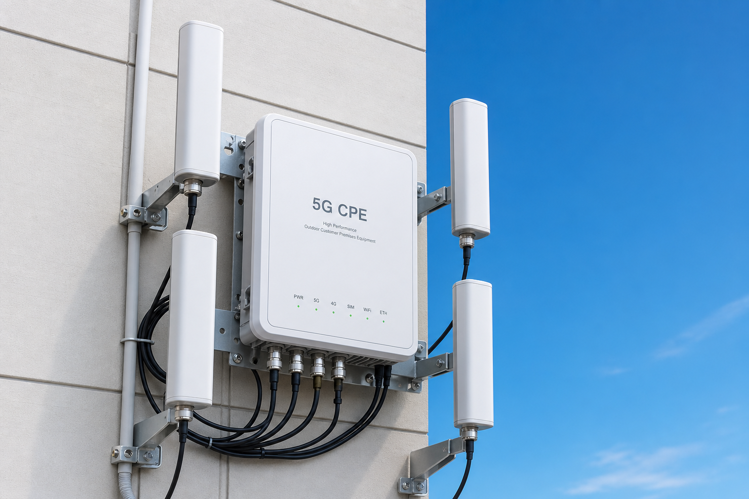
Antenna system design is the single most impactful — and most frequently overlooked — variable in 5G CPE performance. While procurement teams naturally gravitate toward modem chipset specifications, carrier aggregation counts, and theoretical peak throughput figures, the antenna subsystem that converts conducted RF energy into radiated electromagnetic waves ultimately determines whether those impressive silicon capabilities translate into actual throughput at the deployment site. A 5G CPE with a Qualcomm X75 modem and a poorly designed antenna will consistently underperform a device with a mid-tier X65 modem and an optimized antenna system. This article provides B2B buyers and system integrators with a technical framework for evaluating 5G CPE antenna design across MIMO configuration, beamforming implementation, external antenna strategies, and deployment-specific optimization.
MIMO Antenna Architecture: More Than Just Element Count
Multiple-Input Multiple-Output antenna systems are the foundation of 5G NR performance, exploiting spatial diversity and multipath propagation to dramatically increase spectral efficiency. However, the simple specification of “4×4 MIMO” tells procurement teams very little about actual antenna performance. The engineering parameters that matter are:
Antenna Correlation and Isolation: The theoretical capacity gain of MIMO depends on low correlation between antenna elements — meaning each antenna “sees” a sufficiently different version of the radio channel to provide independent spatial streams. In practice, achieving low correlation within the compact form factor of a CPE enclosure requires careful element design, placement optimization, and electromagnetic isolation techniques. Adjacent antenna elements should achieve mutual coupling of less than -15 dB across the operating band, and the envelope correlation coefficient (ECC) should remain below 0.3 — ideally below 0.1 — across frequency. CPE designs that simply place multiple chip antennas on a PCB without isolation structures or spatial diversity optimization often achieve ECC values above 0.5, functionally reducing 4×4 MIMO to 2×2 performance.
Radiation Efficiency and Total Radiated Power (TRP): Antenna radiation efficiency — the ratio of radiated power to input power — directly determines uplink performance, which is often the limiting factor in FWA deployments at cell edge. A well-designed CPE antenna should achieve radiation efficiency of at least 50% (-3 dB loss) across the operating band, with leading designs reaching 65–80% efficiency in sub-6 GHz bands. Total Radiated Power (TRP) measurements — conducted in an anechoic chamber per CTIA or 3GPP test specifications — provide the most meaningful single metric for comparing antenna system performance between CPE platforms. B2B buyers should request TRP and Total Isotropic Sensitivity (TIS) measurement data for candidate CPE across all supported bands, not just the vendor’s best-case frequency.
Polarization Diversity: In indoor and suburban environments, multipath propagation randomizes signal polarization, making dual-polarized antenna elements (+45°/-45° slant polarization) significantly more effective than single-polarized designs. Dual-polarized antennas effectively double the number of usable spatial streams without increasing element count, and they provide resilience against polarization mismatch when the CPE orientation relative to the base station is unknown — as is always the case in self-installed FWA scenarios. CPE platforms targeting enterprise FWA should incorporate dual-polarized antenna elements on at least two of the four MIMO branches, ideally all four.
Beamforming: From Silicon to Antenna
5G NR beamforming is a system capability that spans baseband processing, RF front-end, and antenna design — and the antenna is the component that actually forms the beam in space. Three distinct beamforming architectures appear in 5G CPE designs, each with different performance and cost implications:
Analog Beamforming: The simplest architecture, using phase shifters in the RF path to steer a single beam formed by an antenna sub-array. Analog beamforming is cost-effective and power-efficient but can only form one beam at a time — suitable for basic FWA applications where the CPE communicates with a single gNB with line-of-sight propagation.
Digital Beamforming: The most capable architecture, with independent RF chains and baseband processing for each antenna element, enabling simultaneous multiple beams in different directions. Digital beamforming supports advanced features including multi-user MIMO (MU-MIMO), coordinated multipoint (CoMP) reception, and interference nulling — but requires significantly more RF hardware and baseband processing capability. Enterprise-grade CPE targeting interference-heavy urban deployments should incorporate digital beamforming capability on at least the primary 5G band.
Hybrid Beamforming: A middle-ground architecture that combines analog sub-array beamforming with digital precoding across sub-arrays, achieving much of digital beamforming’s performance at a fraction of the RF hardware cost. Hybrid beamforming is increasingly common in premium enterprise CPE platforms and represents the practical sweet spot for most B2B FWA deployments.
Procurement teams should verify not just that a CPE “supports beamforming” — practically every 5G NR device does at the protocol level — but the specific antenna architecture (analog, digital, or hybrid), the number of independent beams that can be formed simultaneously, and the beam steering range (azimuth and elevation coverage). For CPE installed at fixed locations, beam steering to ±60° azimuth and ±30° elevation typically covers all practical gNB geometries.
Internal vs. External Antenna: The Deployment Decision
The choice between integrated internal antennas and external antenna ports is one of the most consequential decisions in 5G CPE selection, with implications for installation complexity, aesthetic acceptability, and — critically — link budget performance.
Integrated Internal Antennas: Self-contained CPE with internal antennas offers the simplest installation — plug in power, place near a window, and the device is operational. This is the dominant model for consumer and small-office FWA deployments where installation labor cost is the primary constraint. However, internal antennas face fundamental performance limitations: the antenna elements must fit within the CPE enclosure, constraining element size and spacing; the enclosure material (plastic, not metal) and nearby electronics create detuning and absorption effects; and the CPE placement is often suboptimal from an RF perspective, positioned for convenience rather than signal quality.
Well-designed internal antenna CPE can achieve excellent performance in strong-signal environments (RSRP better than -95 dBm). At cell edge (RSRP below -110 dBm), the 8–12 dB of additional gain available from external directional antennas becomes the difference between reliable connectivity and service dropout.
External Antenna Ports: CPE with TS-9, SMA, or N-type external antenna connectors enables the use of high-gain directional antennas — panel, Yagi, or log-periodic designs with 8–14 dBi gain — that dramatically improve link budget in challenging RF environments. External antennas mounted outdoors or in an attic provide two compounding benefits: antenna gain (directly improving both downlink and uplink SNR) and reduced building penetration loss (typically 15–25 dB at sub-6 GHz frequencies for modern energy-efficient construction with low-E glass and foil-backed insulation).
The procurement decision should consider the target deployment environment. For urban and dense-suburban deployments where signal strength is consistently above -100 dBm RSRP, internal antenna CPE performs adequately and simplifies installation logistics. For rural, fringe-coverage, and obstructed deployments — particularly those involving metal-roofed buildings, basement installations, or energy-efficient construction — external antenna capability is not a nice-to-have but a deployment requirement.
External Antenna Selection and Optimization
When deploying external antenna solutions, several engineering parameters determine real-world performance improvement:
Antenna Gain vs. Beamwidth Trade-off: Higher gain (narrower beamwidth) antennas concentrate radiated energy more effectively but require more precise aiming toward the serving gNB. A 10 dBi panel antenna with 60° half-power beamwidth provides a practical balance for most fixed FWA installations — high enough gain to provide meaningful link budget improvement, wide enough beamwidth to tolerate imprecise aiming and seasonal vegetation changes. Ultra-high-gain antennas (14+ dBi) with beamwidths below 30° require professional installation with spectrum analyzer alignment for reliable results.
MIMO External Antenna Configurations: For 4×4 MIMO CPE with external antenna ports, the external antenna configuration must preserve MIMO spatial diversity to maintain multi-stream capability. Simply connecting four identical panel antennas at the same location compromises MIMO decorrelation, reducing 4×4 performance to effectively 2×2. Proper external MIMO antenna deployment requires either a purpose-built 4×4 MIMO panel antenna with cross-polarized element pairs (providing both polarization and spatial diversity in a single housing) or four individual antennas with minimum half-wavelength (approximately 40 cm at 3.5 GHz) spatial separation. The purpose-built 4×4 MIMO panel antenna is strongly preferred for fixed installations — it provides guaranteed polarization diversity and consistent inter-element spacing optimized for MIMO performance.
Cable Loss Budget: The cable connecting the external antenna to the CPE introduces signal loss proportional to cable length and inversely proportional to cable diameter. At 3.5 GHz, typical LMR-200 coax introduces approximately 0.4 dB/meter loss, while premium LMR-400 reduces this to 0.15 dB/meter at the cost of larger diameter and reduced flexibility. For cable runs exceeding 10 meters, the insertion loss can negate a significant portion of the external antenna gain — a 12 dBi antenna connected through 15 meters of LMR-200 delivers only 6 dBi of effective gain at the CPE connector. System integrators should calculate the complete link budget including cable losses and specify cable types and maximum lengths accordingly.
Antenna Design for Specific 5G NR Bands
5G NR’s wide frequency range — from 600 MHz (n71) to 4.2 GHz (n77) in sub-6 GHz, with mmWave bands beyond — presents fundamental antenna design challenges. An antenna element optimized for 3.5 GHz (wavelength approximately 8.6 cm) is electrically too small at 600 MHz (wavelength 50 cm) to achieve reasonable efficiency. This forces multi-band CPE designs into compromise solutions:
Multi-Band Antenna Elements: Single antenna elements that cover multiple bands through techniques such as meandered radiators, parasitic elements, and reconfigurable matching networks. These designs achieve reasonable performance across 600 MHz to 4.2 GHz but with efficiency typically 5–10 dB lower at band edges compared to single-band optimized designs. For CPE targeting diverse global markets, multi-band antennas are the only practical solution.
Band-Specific Sub-Arrays: Premium CPE platforms increasingly incorporate separate antenna sub-arrays for different frequency ranges — typically a low-band array for n5/n8/n28/n71 (600–900 MHz) and a mid/high-band array for n41/n77/n78 (2.5–4.2 GHz). This approach sacrifices none of the efficiency of band-optimized designs at the cost of increased antenna volume and BOM complexity. For CPE deployed in known band environments — for example, a CPE variant targeting European operators using n78 (3.5 GHz) — band-specific antenna optimization provides measurable throughput improvement.
mmWave Antenna Modules: For CPE supporting mmWave bands (n257, n258, n260, n261 at 24–48 GHz), the antenna design transitions from discrete elements to integrated antenna-in-package modules. These modules incorporate phased array antennas, beamforming ICs, and up/down-conversion in a single package, typically supporting 16–64 antenna elements with ±60° beam steering. The procurement consideration for mmWave CPE is not individual antenna element performance but the module’s Effective Isotropic Radiated Power (EIRP) and spherical coverage — metrics that capture the combined antenna array, beamforming, and RF front-end performance.
Antenna Testing and Validation Standards
B2B buyers should verify that CPE antenna systems have been tested and validated to industry-standard methodologies:
- Passive Antenna Testing: S-parameter measurements (return loss, isolation, coupling) conducted with a vector network analyzer across the full operating band, performed in an anechoic chamber to characterize free-space performance without environmental reflections.
- Active Over-the-Air (OTA) Testing: TRP and TIS measurements per CTIA Test Plan for Wireless Device Over-the-Air Performance, conducted in a certified anechoic or reverberation chamber. These measurements capture the complete RF system performance including antenna, front-end, and modem — the metrics most directly correlated with real-world throughput.
- MIMO Throughput Testing: Radiated throughput measurements in a multi-probe anechoic chamber that emulates standardized 3GPP channel models (CDL-A through CDL-E for various propagation conditions). These tests provide the most realistic assessment of how antenna MIMO performance translates to actual user throughput in different environments.
- Desense Testing: Evaluation of how self-generated noise from the CPE’s digital electronics (processor, memory bus, Ethernet PHY, power supply) degrades receiver sensitivity through coupling to the antenna. A well-designed CPE should demonstrate less than 1 dB of desense on all supported bands — poorly designed platforms can suffer 5–10 dB sensitivity degradation, equivalent to reducing the effective cell radius by 40–60%.
Procurement Recommendations
When evaluating 5G CPE antenna designs for B2B FWA deployments, procurement teams should:
- Request TRP and TIS measurement data across all supported bands, not just marketing-optimized frequencies.
- Verify MIMO antenna correlation metrics (ECC below 0.3, isolation above 15 dB).
- For fringe-coverage deployments, specify external antenna port availability with TS-9 or SMA connectors on all MIMO branches.
- Confirm beamforming architecture (analog, hybrid, or digital) and simultaneous beam count.
- Evaluate desense performance — request conducted vs. radiated sensitivity comparison data.
- Consider band-optimized CPE variants for single-region, known-band deployments where antenna efficiency optimization matters most.
- Include cable loss budget in total link budget calculations when planning external antenna deployments.
The antenna system is not a commodity component that can be specified by element count alone. For B2B deployments where consistent throughput at range defines operational success or failure, antenna design quality is among the highest-leverage procurement criteria — and one that deserves significantly more technical scrutiny than it typically receives in CPE RFPs.
This technical guide was prepared by the Honlly Telecom RF engineering team. For antenna performance data, radiation pattern measurements, or technical consultation on CPE antenna optimization for your specific deployment environment, contact our solutions engineering group at sales@xmhonlly.com.