
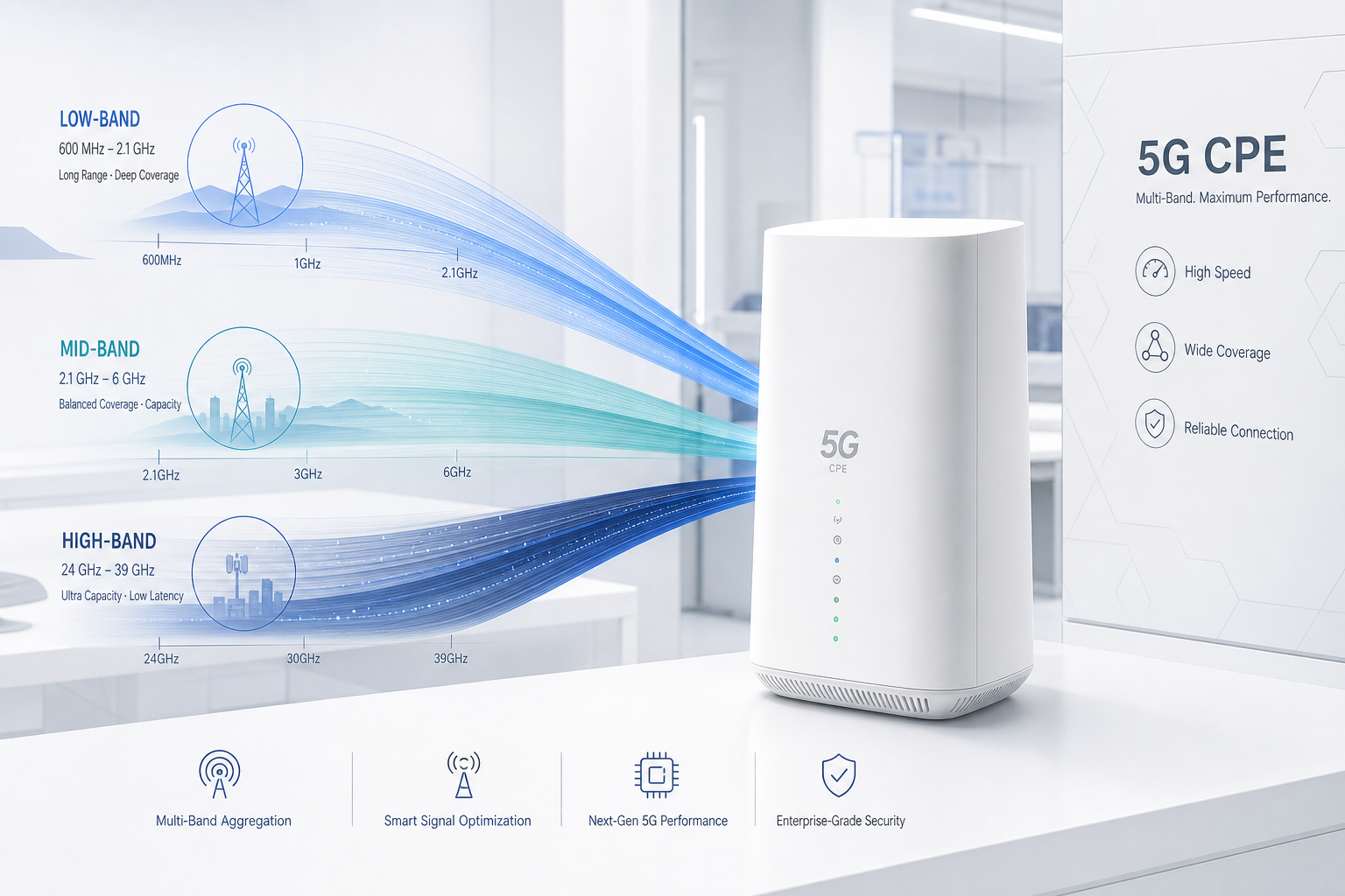
For enterprise network engineers deploying 5G Fixed Wireless Access at scale, two radio access technologies determine whether the CPE delivers carrier-grade throughput or underwhelming performance: Carrier Aggregation (CA) and Multi-Input Multi-Output (MIMO). Understanding how these technologies interact — and how to optimize them for real-world deployment conditions — separates successful enterprise FWA rollouts from expensive disappointments.
This engineering deep dive examines the technical architecture of CA and MIMO in 5G CPE, provides practical optimization strategies, and addresses the most common performance pitfalls encountered in B2B deployments.
Carrier Aggregation Fundamentals in 5G NR
Carrier Aggregation enables 5G CPE to simultaneously transmit and receive data across multiple frequency carriers, effectively multiplying available bandwidth. In 3GPP Release 17, up to 16 component carriers (CCs) can be aggregated in the downlink, though commercial CPE implementations typically support 4–8 CC aggregation depending on the modem platform.
The practical significance for enterprise FWA is substantial. A single 100 MHz carrier in the n78 band (3.5 GHz) can deliver approximately 1.5 Gbps peak downlink throughput with 4×4 MIMO and 256-QAM. Aggregating three such carriers pushes peak throughput past 4 Gbps — performance levels that rival fiber access and enable enterprise applications like real-time cloud backup, 4K video conferencing, and large-scale IoT data aggregation.
Inter-Band CA: The Throughput Multiplier
Inter-band CA — aggregating carriers across different frequency bands — is where the most significant performance gains are realized in real-world deployments. The most common and effective inter-band CA combinations for enterprise FWA include:
Low-Band + Mid-Band (n5 + n78 / n28 + n78): The low-band carrier (600–900 MHz) provides coverage reach and uplink robustness, while the mid-band carrier (3.3–4.2 GHz) delivers the bulk of downlink capacity. This combination is particularly effective for suburban and rural enterprise deployments where mid-band coverage may be marginal at the cell edge. The low-band anchor ensures session continuity and control-plane reliability, while mid-band CA boosts user-plane throughput.
Mid-Band + Mid-Band (n78 + n78): In dense urban deployments with strong mid-band coverage, intra-band contiguous or non-contiguous CA within the n78 band can double or triple throughput without requiring low-band spectrum. This is the most common CA configuration for urban enterprise FWA, with typical commercial implementations supporting 2CC or 3CC n78 aggregation.
Mid-Band + mmWave (n78 + n257/n258): For fixed installations in mmWave coverage areas, aggregating a mid-band anchor with mmWave capacity bands (24–40 GHz) can push peak throughput beyond 7 Gbps. This configuration is ideal for enterprise headquarters, data center interconnection, and high-capacity backhaul applications.
CA Activation Dynamics and UE Capability
Not all 5G CPE devices are created equal in terms of CA capability. The 3GPP UE capability framework defines several critical parameters that B2B buyers should verify in CPE specifications:
- ca-BandwidthClassDL: Defines the maximum number of CCs and total aggregated bandwidth the CPE can support. Class E supports up to 4 CCs with up to 800 MHz total bandwidth; Class G supports up to 8 CCs with up to 1.6 GHz.
- supportedBandCombination: The specific set of band combinations the CPE’s modem supports for CA. A CPE that supports n78+n78+n78 but not n5+n78+n78 will perform differently depending on available spectrum in the deployment location.
- maxNumberMIMO-LayersPDSCH: The maximum number of MIMO layers per component carrier — critical for determining per-carrier throughput contribution to the aggregated total.
4×4 MIMO: Spatial Multiplexing and Throughput Scaling
While CA multiplies bandwidth, MIMO multiplies spectral efficiency. 4×4 MIMO uses four transmit and four receive antennas to create up to four parallel spatial streams (layers), each carrying independent data. In ideal conditions — high SINR, low correlation between antenna paths — 4×4 MIMO can approximately double throughput compared to 2×2 MIMO on the same bandwidth.
MIMO Layer Count and Rank Indicator
The number of spatial layers actually used — indicated by the Rank Indicator (RI) reported by the CPE to the gNB — is determined by the radio channel’s spatial richness. In enterprise FWA deployments, achieving and sustaining Rank 4 (four spatial layers) requires careful attention to antenna placement and RF environment:
- Antenna Correlation: The four antenna elements must have sufficiently low correlation — typically <0.3 for Rank 4 operation. This requires antenna spacing of at least λ/2 (approximately 4.3 cm at 3.5 GHz) and preferably λ (8.6 cm) for robust multi-path decorrelation.
- Angular Spread: Rich multi-path environments — urban deployments with building reflections, indoor installations with metallic structures — naturally create the angular spread needed for spatial multiplexing. Rural line-of-sight deployments often exhibit lower rank due to limited multi-path, even with strong SINR.
- Polarization Diversity: Dual-polarized antenna arrays (±45° slant polarization) are standard in modern 5G CPE and contribute two orthogonal polarization paths per antenna pair, enhancing rank potential without increasing physical antenna spacing.
Throughput Scaling: Theory vs. Reality
Understanding the gap between theoretical peak throughput and real-world performance is essential for setting deployment expectations. Consider a typical enterprise FWA deployment with 100 MHz of n78 spectrum and 4×4 MIMO:
| Scenario | SINR | Rank | MCS | DL Throughput |
|---|---|---|---|---|
| Theoretical Peak | >30 dB | 4 | 256-QAM | ~1.5 Gbps |
| Excellent Real-World | 20–25 dB | 4 | 64-QAM | ~800–950 Mbps |
| Good Real-World | 15–20 dB | 3 | 64-QAM | ~500–650 Mbps |
| Moderate Real-World | 10–15 dB | 2 | 16-QAM | ~200–350 Mbps |
| Cell Edge | <5 dB | 1 | QPSK | ~30–80 Mbps |
The key insight for B2B network engineers: adding CA can compensate for lower MIMO rank. A deployment that achieves only Rank 2 on a single 100 MHz carrier (350 Mbps) can potentially reach 1+ Gbps if it aggregates three such carriers — even if each operates at Rank 2.
Practical Optimization Strategies for Enterprise Deployments
1. Antenna Placement and Orientation
For outdoor CPE with external antenna ports, antenna placement is the single most impactful optimization variable. Best practices include:
- Mount antennas with clear line-of-sight to the serving gNB whenever possible
- Maintain at least 1 meter separation between the CPE’s antennas and any metallic structures (building cladding, HVAC equipment, solar panels) that can create destructive reflections
- Use cross-polarized antenna pairs at ±45° to maximize polarization diversity
- For 4×4 MIMO configurations, arrange antennas in a square or diamond pattern with λ/2 spacing minimum
2. Band Selection and CA Combination Locking
Most 5G CPE firmware allows network engineers to lock preferred bands and CA combinations. Strategic band locking can prevent the CPE from camping on sub-optimal carriers:
- In deployments with strong n78 coverage, lock to n78 as the primary carrier to prevent the CPE from falling back to lower-capacity low-band carriers
- Configure preferred CA combinations that match the operator’s actual spectrum deployment — a CPE attempting to aggregate a band combination the network doesn’t support wastes time in unsuccessful CA configuration attempts
- Use AT commands or TR-369 USP to programmatically set band preferences across large CPE fleets based on per-site RF survey data
3. SINR Optimization Through Interference Management
In dense urban deployments, inter-cell interference is often the primary limitation on SINR and, consequently, MIMO rank. Mitigation strategies include:
- Using directional antennas (narrow beamwidth, high front-to-back ratio) to spatially filter interference from non-serving cells
- Positioning CPE antennas to maximize the serving cell RSRP while minimizing RSRP from the strongest interfering neighbor cell — a difference of >6 dB is typically sufficient for robust Rank 3–4 operation
- Leveraging the CPE’s built-in cell lock feature to prevent ping-pong handovers between cells with similar signal strength
4. CPE Modem Platform Selection
The modem platform inside the CPE fundamentally constrains CA and MIMO capability. For enterprise FWA deployments targeting >1 Gbps sustained throughput, B2B buyers should verify:
- Modem supports a minimum of 4CC CA for sub-6 GHz bands (Qualcomm X70/X75, MediaTek T800, or equivalent)
- 4×4 MIMO support on all aggregated carriers (not just the primary carrier)
- 256-QAM in downlink and 64-QAM in uplink as minimum modulation orders
- UL CA and UL-MIMO support for deployments requiring symmetric or high-uplink performance (video surveillance backhaul, cloud upload, real-time telemetry)
Testing Methodology for Enterprise Validation
Before scaling a CPE deployment across dozens or hundreds of sites, B2B network engineers should validate CA and MIMO performance at representative pilot sites. A structured testing methodology should include:
- Baseline Single-Carrier Measurement: Lock the CPE to each available carrier individually and measure throughput, SINR, RSRP, RSRQ, and RI at multiple times of day. This establishes the performance floor for each band.
- CA Combination Testing: For each supported CA combination, measure the incremental throughput gain. Some combinations may deliver less-than-linear scaling due to RF front-end limitations or scheduling conflicts at the gNB.
- Mobility Stress Testing: For semi-fixed deployments (construction sites, event venues), test CA and MIMO stability during antenna micro-movements. Wind-induced antenna sway can cause rank fluctuations.
- Load Condition Testing: Test during peak network load hours (typically 11:00–13:00 and 18:00–21:00 local time). Carrier aggregation gains may diminish when the serving cell is heavily loaded, as the scheduler distributes resources across more UEs.
- Failover Behavior: Verify that the CPE gracefully degrades — falling back to fewer CCs and lower rank — rather than dropping connectivity entirely when CA conditions degrade.
Conclusion: The CA+MIMO Engineering Imperative
For B2B deployments where throughput consistency directly impacts business operations — retail point-of-sale systems, construction site connectivity, remote office SD-WAN backhaul — treating CA and MIMO optimization as a one-time site survey checkbox is a recipe for underperformance. These are dynamic radio phenomena that require ongoing monitoring and adjustment as network conditions, spectrum allocations, and interference environments evolve.
Enterprises that invest in understanding and optimizing CA and MIMO configurations for their 5G CPE fleets will consistently achieve 2–4x the throughput of those who accept default settings. In an era where enterprise connectivity is increasingly mission-critical, that performance delta is not merely a technical curiosity — it is a competitive advantage.