
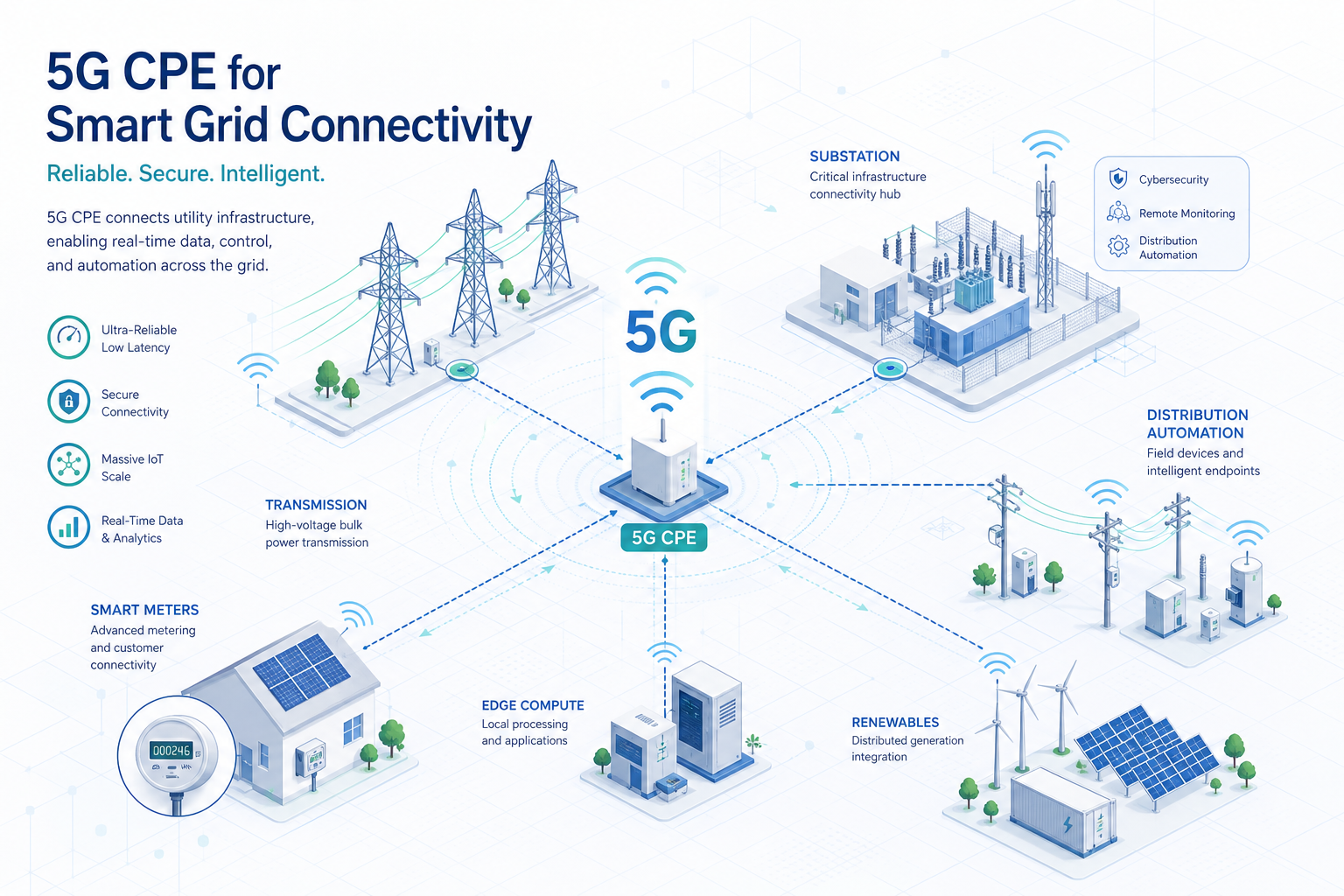
The global utility sector is undergoing its most significant communications infrastructure transformation in decades. As grid modernization initiatives accelerate—driven by distributed energy resource (DER) integration, advanced metering infrastructure (AMI) expansion, and distribution automation requirements—utilities are increasingly evaluating 5G fixed wireless access as a strategic alternative to legacy private radio networks and fiber builds. This technical buyer’s guide examines the specific requirements, architectures, and evaluation criteria for deploying 5G CPE in smart grid and utility environments.
The Utility Communications Challenge
Utility communications networks must satisfy a uniquely demanding set of requirements that conventional enterprise networking equipment was never designed to meet. Substation automation protocols demand deterministic latency below 10 milliseconds for protection relaying (IEC 61850 GOOSE messages). AMI backhaul must support hundreds of thousands of endpoints per concentrator with efficient multicast and periodic burst tolerance. Distribution automation requires 99.999% availability in environments subject to extreme temperatures, electromagnetic interference, and physical stress. And all of this must operate within the regulatory frameworks governing critical infrastructure protection, including NERC CIP in North America and NIS2 in Europe.
5G—specifically the ultra-reliable low-latency communication (URLLC) and massive machine-type communication (mMTC) capabilities standardized in 3GPP Release 15 through 18—offers a compelling technical foundation for utility communications. However, the CPE device that terminates the 5G connection at the substation, pole-top, or meter concentrator is where theoretical capability meets operational reality.
AMI Backhaul: Connecting Millions of Meters
Advanced metering infrastructure represents the largest-scale communications challenge in the modern grid. A single utility may operate 2–5 million smart meters, each generating periodic consumption data, event alerts, and firmware update requests. These meters typically connect through neighborhood-area networks (NANs) using RF mesh (802.15.4g Wi-SUN, LoRaWAN, or proprietary protocols) that aggregate at concentrator points—and it is at these concentrators where 5G CPE provides the wide-area backhaul link.
The CPE requirements for AMI backhaul are distinct from typical enterprise FWA use cases. First, the traffic pattern is highly asymmetric: predominantly uplink with periodic meter read bursts that can generate 50–100 Mbps of sustained uplink traffic per concentrator during the nightly read window. Second, multicast efficiency is critical for firmware distribution and demand-response commands that must reach thousands of meters simultaneously. Third, the CPE must support VLAN segmentation to isolate metering traffic from distribution automation traffic sharing the same physical backhaul link.
When evaluating CPE for AMI backhaul, procurement teams should verify: support for 5G NR uplink-heavy frame configurations (particularly TDD patterns with uplink-predominant slot ratios), efficient multicast-to-unicast conversion or native 5G multicast/broadcast service (MBS) support, and hardware-accelerated VLAN tagging with at least 16 concurrent VLAN interfaces for traffic segmentation.
Distribution Automation and Substation Connectivity
Distribution automation (DA) encompasses the sensors, controllers, and actuators that enable real-time grid monitoring and autonomous fault response. At the substation level, intelligent electronic devices (IEDs) communicate using IEC 61850 protocols—GOOSE for high-speed protection messaging, MMS for monitoring and control, and SV (sampled values) for synchronized measurement data. 5G CPE serving as substation WAN gateways must transparently transport these protocols with deterministic latency characteristics.
The critical CPE requirements for DA and substation applications include: URLLC support with configurable 5QI values (5QI 3 for critical machine-type communication with 10ms packet delay budget), hardware timestamping (IEEE 1588v2 Precision Time Protocol) with sub-microsecond accuracy for synchrophasor applications, seamless redundancy via dual-SIM or dual-modem configurations with hitless failover below 50ms, and IEC 61850-3 / IEEE 1613 compliance for electromagnetic compatibility in high-voltage environments.
Environmental hardening deserves particular attention. Substation CPE must operate reliably in ambient temperatures from -40°C to +75°C, withstand electromagnetic interference from disconnect switches and fault currents, and maintain connectivity through voltage sags and surges. Conformal coating of PCBs, industrial-temperature-rated components, and fanless thermal design are non-negotiable for this deployment class.
Network Slicing for Multi-Service Utility Networks
5G network slicing is particularly valuable for utility deployments, where a single physical CPE may need to support multiple logical networks with radically different QoS requirements. A typical utility CPE might terminate three slices simultaneously: a URLLC slice for protection relaying (5QI 3, guaranteed bit rate, 5ms latency target), an eMBB slice for video surveillance and remote inspection (5QI 7, non-GBR, 100ms latency), and an mMTC slice for AMI backhaul (5QI 9, non-GBR, 300ms latency).
CPE platforms targeting utility deployments must support 3GPP-defined UE route selection policy (URSP) rules that map application traffic to the appropriate network slice based on traffic descriptors (IP tuples, FQDN, DNN, or application ID). Procurement teams should verify that candidate CPE supports at least 8 concurrent PDU sessions, each independently configurable with distinct SSC modes and session continuity requirements, to accommodate the multi-slice utility architecture.
Security for Critical Infrastructure
Utility CPE security requirements extend well beyond standard enterprise networking. In North America, NERC CIP-005-7 mandates electronic security perimeters with access control and monitoring for all cyber assets connected to the bulk electric system. In Europe, the NIS2 Directive imposes similar requirements with significant financial penalties for non-compliance.
At minimum, utility-grade CPE must provide: hardware root of trust with secure boot and firmware attestation (see our companion guide on Zero Trust Security for 5G CPE), IPsec tunnel termination with IKEv2 and certificate-based mutual authentication, role-based access control with TACACS+/RADIUS integration for administrative access, syslog forwarding with reliable transport (TLS-encrypted) to utility SIEM platforms, and NERC CIP-compliant configuration management with audit trails and change detection.
Deployment Architecture Considerations
Utility 5G CPE deployments typically follow one of three architectural models. The first is public network with network slicing, where the utility contracts slicing services from a mobile network operator, using dedicated slices with guaranteed QoS. This model minimizes capital expenditure but depends on the operator’s geographic coverage meeting substation and pole-top locations. The second model is hybrid public-private, where the utility operates a private 5G RAN at critical sites (using shared or dedicated spectrum such as CBRS in the US or n77/n78 globally) and falls back to public network slicing elsewhere. The third model is fully private 5G, where the utility builds and operates its own RAN and core network, suitable for large utilities with existing spectrum holdings or those operating in regions with enterprise spectrum licensing frameworks.
CPE selection should align with the chosen deployment model. For public-network-sliced deployments, CPE must support operator-provisioned URSP policies and inter-PLMN mobility. For private or hybrid models, CPE must additionally support SNPN (standalone non-public network) credentials and credential holder (CH) based authentication as defined in 3GPP TS 23.501.
Procurement Evaluation Checklist
- URLLC Support: Configurable 5QI values including 5QI 3 (10ms PDB), verified end-to-end latency under utility-specific traffic profiles
- Precision Timing: IEEE 1588v2 hardware timestamping with sub-microsecond accuracy, GNSS-disciplined oscillator for holdover during GPS outages
- Multi-Slice Capability: Minimum 8 concurrent PDU sessions, URSP rule processing, independent SSC mode per session
- Environmental Hardening: -40°C to +75°C operating range, IEC 61850-3 / IEEE 1613 EMC compliance, IP67 or higher ingress protection, fanless design
- Redundancy: Dual-SIM with automatic failover below 50ms, dual radio support for link aggregation or 1+1 protection
- Security Compliance: Hardware root of trust, secure boot, IPsec/IKEv2 with certificate-based mutual auth, NERC CIP-005-7 / NIS2 alignment
- Management: NETCONF/YANG for configuration management, SNMPv3 with AES encryption for monitoring, TR-369 USP for ACS integration
- Deployment Model Flexibility: Public network slicing, SNPN/CAG for private networks, inter-PLMN mobility support
- Protocol Support: Transparent transport for IEC 61850 GOOSE/MMS/SV, IEEE C37.118 synchrophasor timing, DNP3 and Modbus TCP for legacy integration
Conclusion
Utilities evaluating 5G CPE for smart grid deployments face a more complex procurement landscape than typical enterprise FWA buyers. The convergence of deterministic latency requirements, extreme environmental conditions, multi-service network slicing, and critical infrastructure security compliance demands CPE platforms purpose-built for the utility vertical. As grid modernization accelerates through 2030, the 5G CPE serving as the communications gateway at substations and distribution points will play an increasingly strategic role in grid reliability, resilience, and operational efficiency.
This guide is part of Honlly Telecom’s Technical Buyer’s Guide series. For detailed specifications of Honlly’s utility-grade 5G CPE platforms or to discuss your smart grid communications requirements, contact our industrial solutions team.